1602 LCD Contrast Control From Arduino
by taste_the_code in Circuits > Arduino
35794 Views, 11 Favorites, 0 Comments
1602 LCD Contrast Control From Arduino


While working on a new project I’ve came across a problem where I wanted to control the backlight and the contrast of an 1602 LCD display through an Arduino but the display was really flickery.
Typical Use Case


In a typical use case, the display contrast is adjusted through a variable resistor as per the datasheet. In such case, through the resistor we can adjust the voltage that is seen on the V0 pin and the contrast is adjusted accordingly. With the Arduino, the best thing we can output is a PWM signal with a different cycle but unfortunately the module is not happy displaying that.
Code Used on the Example


Before going into the schematic how we can fix this, let me explain you the code that I’m using.
The first thing we need to do is to include the Liquid Crystal library so we can connect to the display. Next, we setup the LCD with the pins that we have our display connected to and additionally we define the pins that we have our backlight and contrast pins connected to. The contrast control pin on the display is V0 and it is connected to pin 6 on the Arduino and the backlight control pin is marked as A and since this is basically an LED, it is connected through a 220 Ohm resistor to pin 10 on the Arduino.
In the Setup function we first set the brightness on the display to the max and then we start communication with the LCD. To make sure that it is working correctly, we display a message of “hello world” and we wait for about half a second so we can verify that the output is OK.
Very often, depending on the state of the V0 pin, you might face the issue of not having anything displayed even though the expectation was different. The reason for this is the contrast pin value. If the contrast is set too high, the display is barely visible so we need to decrease it.
In the loop section of the code we first clear out the contents of the LCD and since we gonna programmatically change the contrast we display a text and in a loop we update the pin output and display the current value to the display on the second row.
Downloads
Implement Low Pass RC Filter


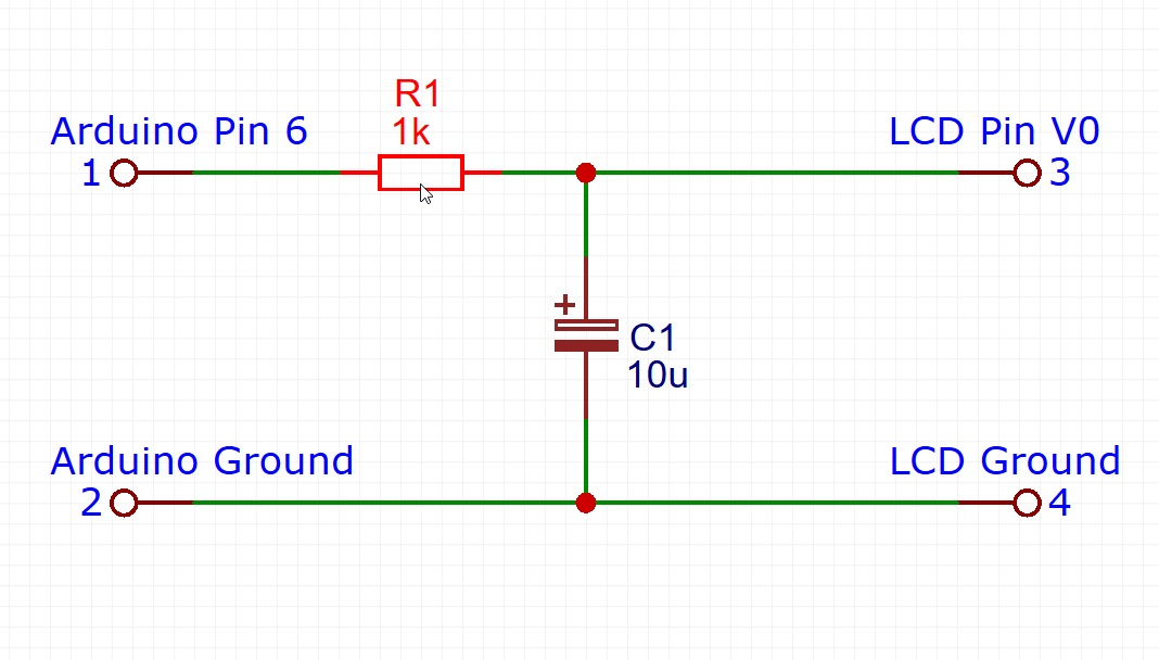
As you can see, this seems to be working but the display is all flickery. The reason for this is that the display expects a fixed voltage but instead it gets a PWM signal from the Arduino. To fix this we add a very simple low pass RC filter so the output voltage can be filtered and we get a relatively stable output.
The low pass filter is composed of a 1 kOhm resistor that on one side is connected to the pin 6 on the Arduino and then to V0 on the display. The 10 uF capacitor is connected with its negative side to ground and the positive is connected to the V0 pin. The resistor charges the capacitor with the PWM pulses and depending on the duty cycles its charged to a different voltage.
Programmatically Control the Back Light

Similar to how we set the contrast, we can do the same to the backlight pin but without the need of adding a low pass filter since the backlight LED is not visible while being switched on and off so fast.
Enjoy!

I hope that this very simple trick will help you with your next project. If you liked this Instructable then please consider following me and Subscribe to my YouTube channel.
Cheers!