2-Digit Green Binary Counter
by braulio777 in Circuits > Electronics
2041 Views, 13 Favorites, 0 Comments
2-Digit Green Binary Counter


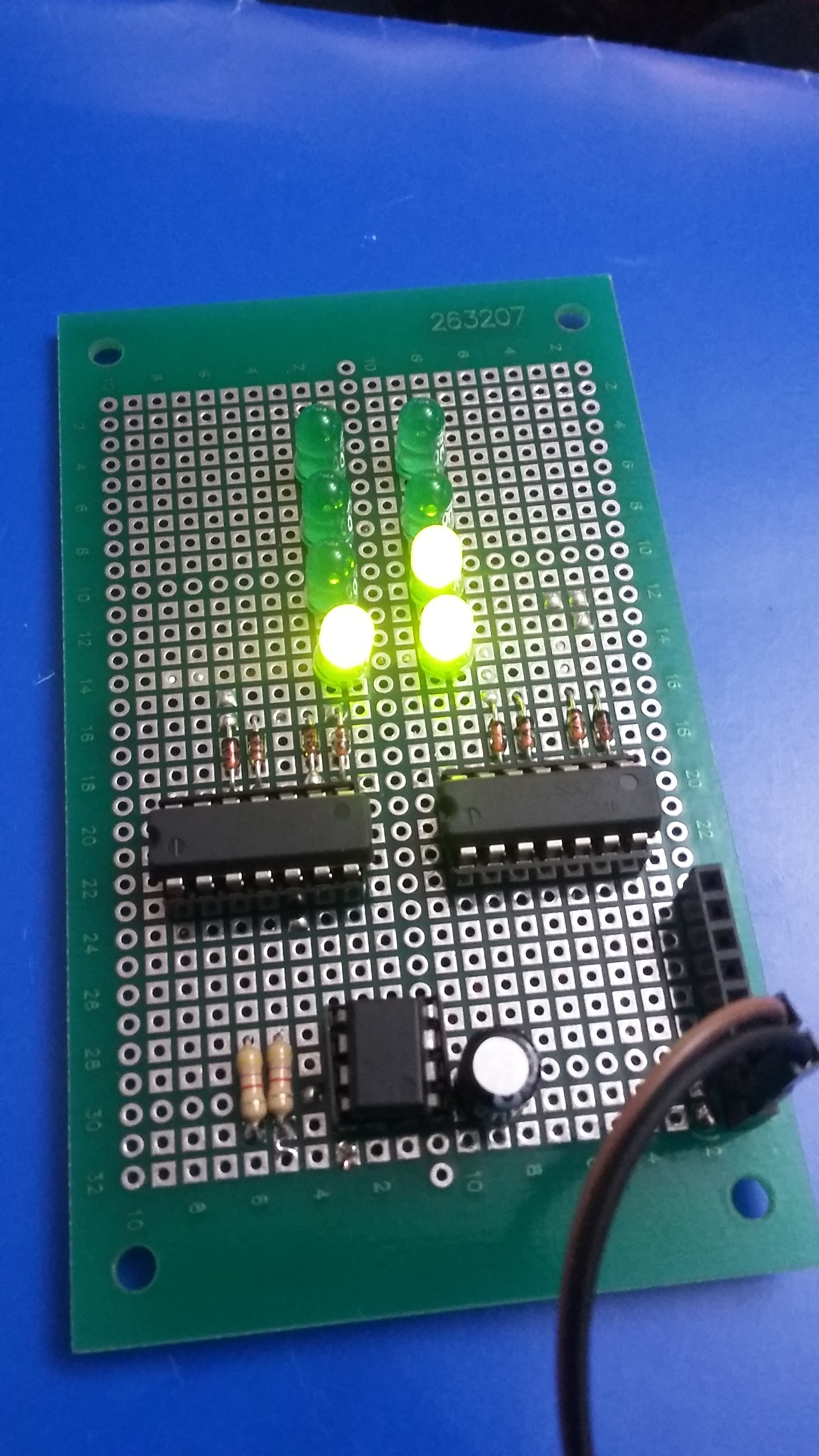
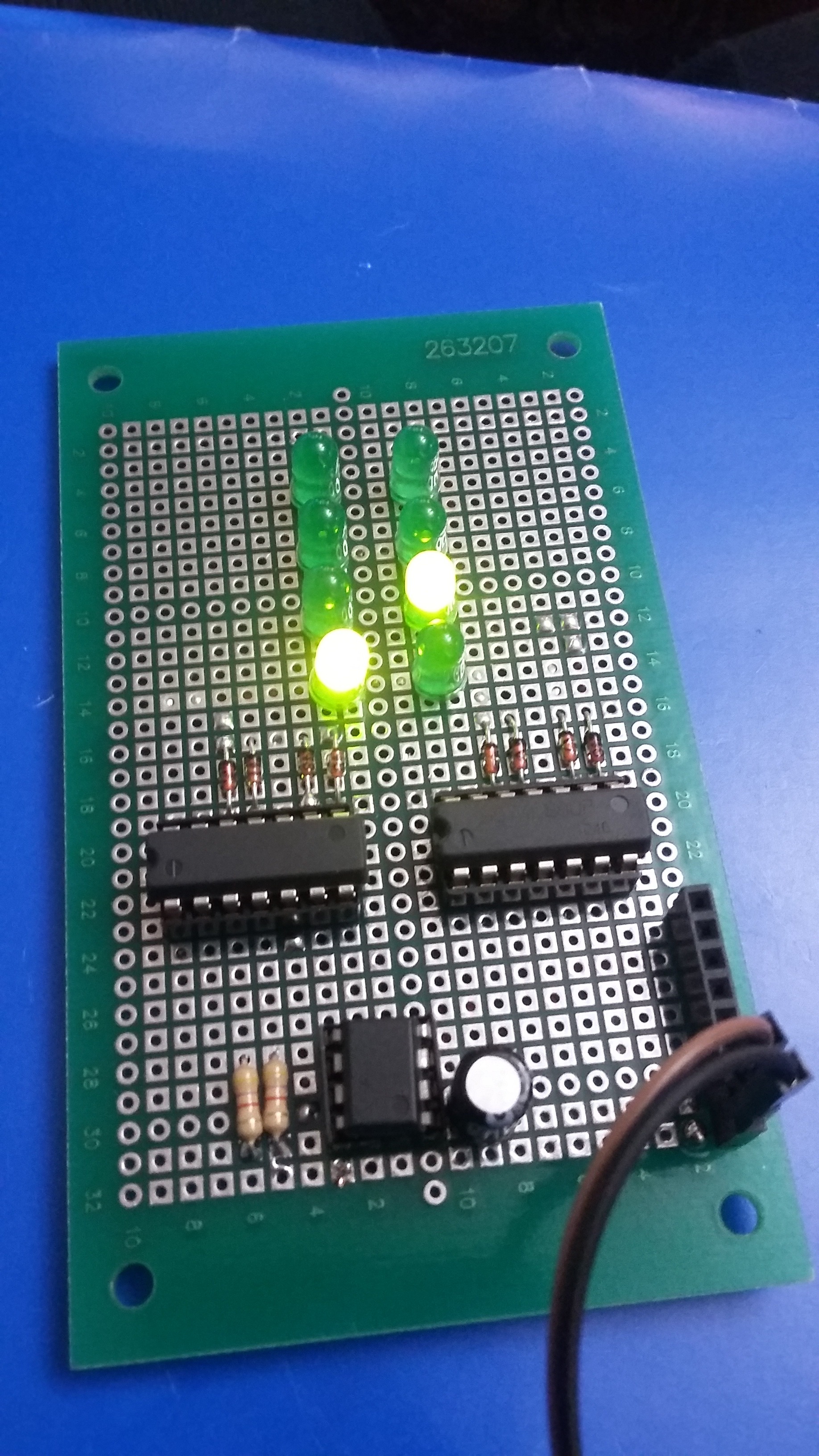
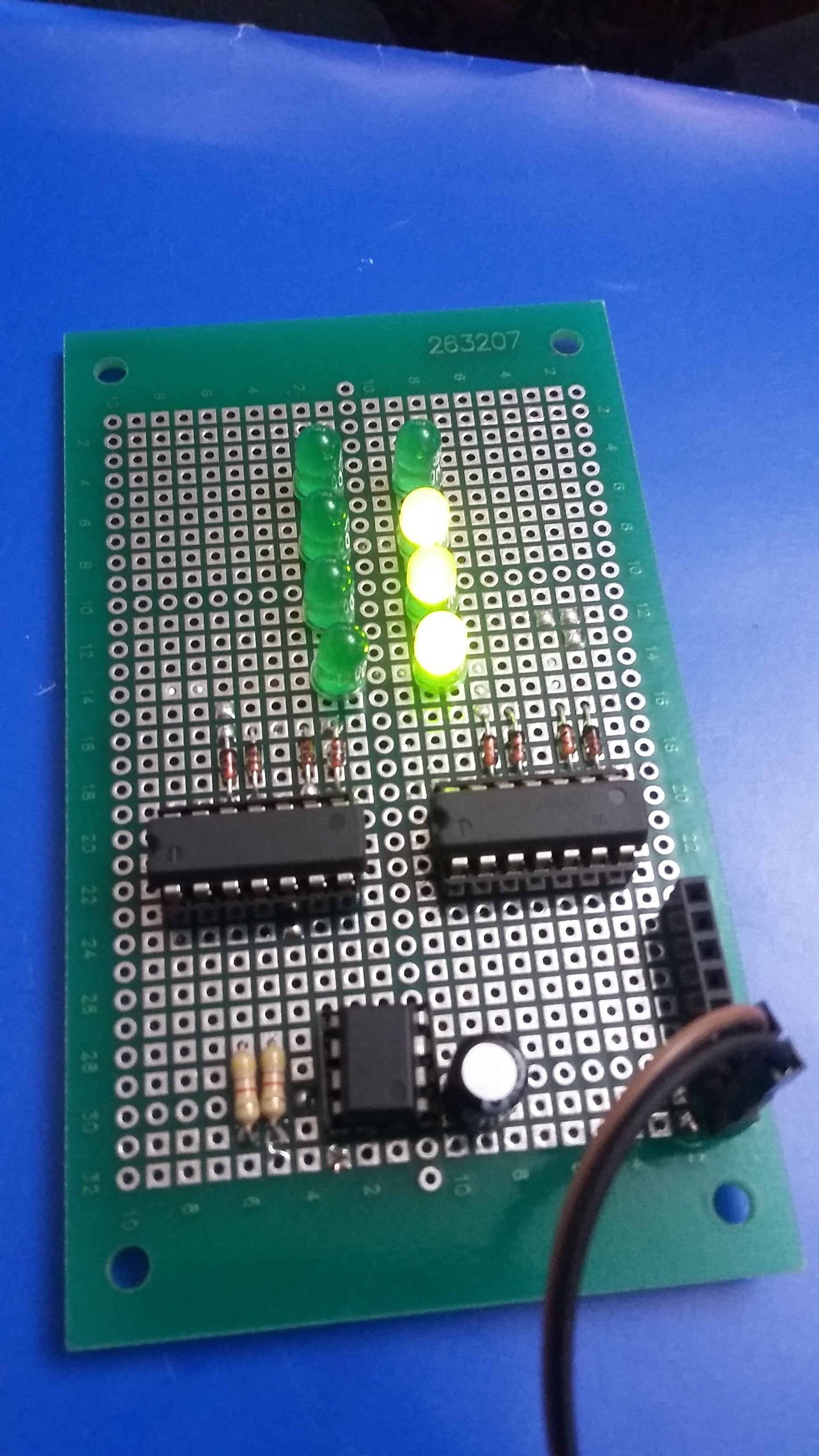
This project is part of a set of three counters before beginning to work with my Binary Clock. They are the Green Binary Counter, my previous project, 2-Digit Binary Counter, this project, and the next project. In the present project, I'm using 2-IC7490, 1-IC555, 8 diodes: 1N914, 8-5mm LED, 2-4.7K resistor, and 1-100uF capacitor. 2-Digit Binary Counter counts from 0 to 99 with binary code.
Bill of Materials


1-PCB, Jameco 263207
2-14 pin socket
1-8 pin socket
2-IC7490 counter
1-IC555 timer
1-100uF capacitor
2-4.7K resistor
8-1N914 diode
8-5mm LED, any color
Schematic

Follow step by step the diagram's diagram if you want to complete the project successfully.
Beginning the Project


Insert the pin sockets, the diodes, and the LEDs. Note that you have to connect the 7490's pin-socket 8, 9, 11, and 12 to the respective anodes of each diode while leaving free its cathodes (black line up on the diode's body). You should also connect the LED's cathodes.
Connecting Positive Side of LEDs 1


Connect the positive side of LEDs 1 to its respective cathode of each diode by coming from IC7490's pin socket 12.
Connecting Positive Side of LEDs 2


Connect the positive side of LEDs 2 to its respective cathode of each diode by coming from IC7490's pin socket 9.
Connecting Positive Side of LEDs 3


Connect the positive side of LEDs 3 to its respective cathode of each diode by coming from IC7490's pin socket 8.
Connecting Positive Side of LEDs 4


Connect the positive side of LEDs 4 to its respective cathode of each diode by coming from IC7490's pin socket 11. You can also install the capacitor between the pin 1 & 2 from IC555 timer to its negative and positive terminal respectively.
Doing a Few Connections


Do a few connections and install the resistors so that you can complete IC555 timer's connections while continuing working with GND's connections too.
Completing the Project


Complete the connections and insert the integrated circuits on theirs respective pin-sockets.
Using the Project


.jpg)

.jpg)


.jpg)

.jpg)

Use your project so that you know if it functions correctly or back to your schematic for checking whether everything is OK.