2 Player Microbit Pong

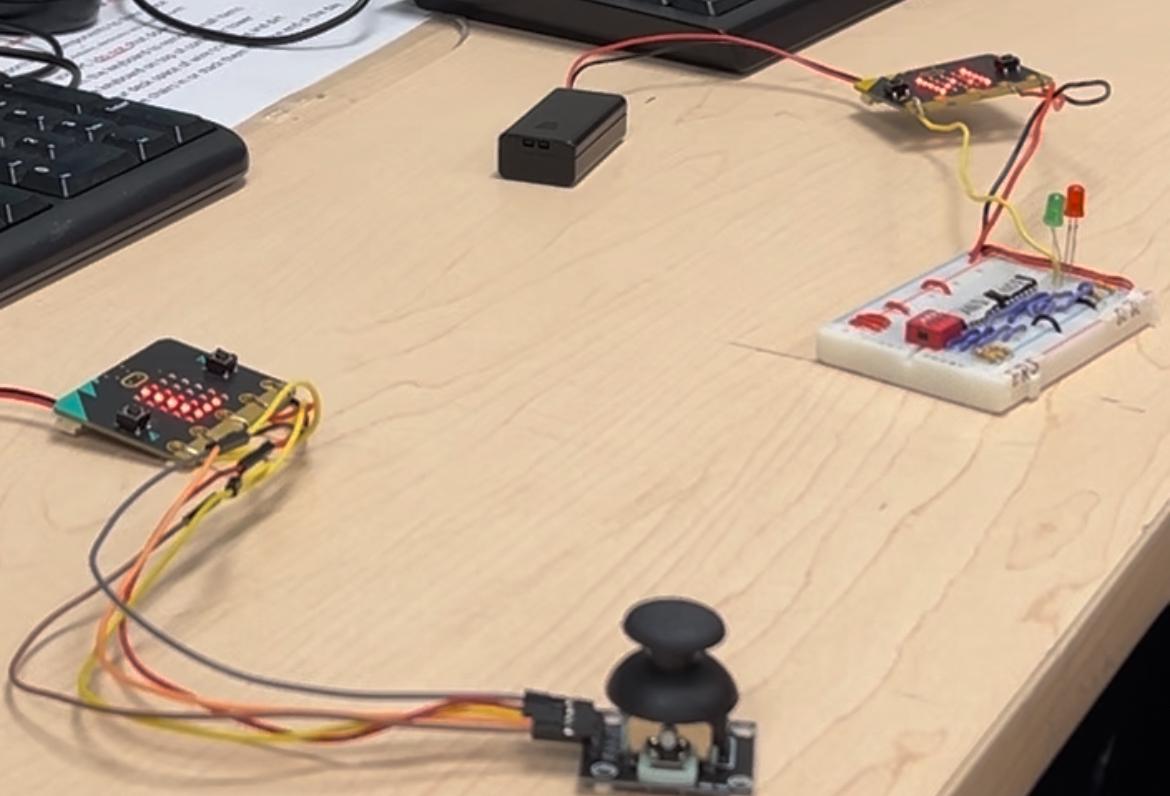
In this project, we will be making a 2 Player pong game using 2 micro bits that communicate with each other to function as 1 screen. 1 micro bit uses a joystick to move its paddle up and down whilst the other uses the built in buttons as well as 2 power ups. 1 slows the ball down upon shaking the micro bit as well as inverting the balls direction touching the built in touch sensor. The micro bits also connect to a gated NOR SR latch that functions as a pause switch that temporarily pauses the game when q not is high.
Supplies
(2) Micro bit microcontrollers $78.37x2 = $156.74
(1) Joystick (HW-504) $11.99
(5) Female to female wires $20.95 (pack of 120) $20.95/120*5 = $0.87
(1) Mini breadboard $9.00 (pack of 3) $9.00/3 = $3.00
(1) Dip switch $10.69 (pack of 5) $10.69/5 = $2.13
(3) 10k ohm resistors $11.27 (pack of 250) $11.27/250*3 = $0.12
(2) 330 ohm resistors $9.78 (pack of 100) $9.78/100*2 = $0.18
(1) Quad AND gate chip (7408) $32.34 (pack of 20) $32.34/20 = $1.61
(1) Quad NOR gate chip (7402) $11.38 (pack of 10) $11.38/10 = $1.13
(1) Green LED $13.00 (pack of 100) $13.00/100 = $0.13
(1) Red LED $11.03 (pack of 100) $11.03/100 = $0.11
Total Cost: $156.74 + $11.99 + $0.87 + $3.00 + $2.13 + $0.12 + $0.18 + $1.61 + $1.13 + $0.13 + $0.11
= $178.01
Idea and Research
For this project we wanted to create a game that would interface 2 micro bits together to create a 2 player game. We came up with the idea of using both micro bits to form one effective screen and interface them using the built in radio functionality. The project is particularly code heavy as the micro bit's contain many built in components so the python micro bit documentation was reviewed often. We also wanted to add peripherals, a joystick was an obvious choice for a game related project. Researching how to interface a joystick with a micro bit. Another peripheral we wanted to implement to add additional depth to the project was a circuit involving logic gates. Adding a logic gate based component to the project would require the micro bit to take input from the external circuit, send it to the other micro bit and then apply it some way in the code. We went with a gated SR latch and chose the idea for pausing, as it was a simple game function that would require both micro bits to communicate to each other. This functionality was chosen because it would be difficult for players to switch between holding the micro bit/joystick, however pausing is a feature which avoids this issue.
Connecting the Joystick


Using the female to female wires in combination with regular wires that are trimmed such that the exposed metal can wrap around the micro bit's pin locations to connect the joystick to the left micro bit. Connect VCC and ground to their respective pins on the micro bit. Whilst you can connect the remaining joystick pins to any of the remaining micro bit pins so long as you change the pin numbers in the code, in our code we connected VRy to pin 0, VRx to pin 1, and SW to pin 2.
Constructing the Gated SR Latch: Placing Components


First place the dipswitch, AND and NOR gate chips as well as both LED outputs (representing Q and Q not) for the latch onto the mini breadboard.
Then jump power from the power rail using wires to 3 of the top pins of the dipswitch (representing Enable, Reset, and Set) and jump ground from the ground rail using 10k Ohm resistors to the corresponding bottom pins of the dipswitch.
Next Jump power and ground from the corresponding rails to the VCC and GND pins of the AND and NOR chips (Top left and bottom right respectively)
Finally, jump ground to the cathodes of the LED's using 330 Ohm resistors
Constructing the Gated SR Latch: Logic Connections


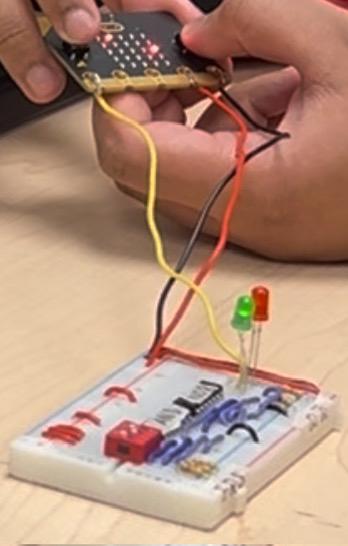
Now that we have placed the components, we need to string the logic together to create the latch. A schematic and picture of the real circuit is provided above.
The general rundown is connecting set and reset to their own AND gates with the second AND gate input coming from enable. The the outputs of the AND gates connect to their own respective NOR gates, the output of these gates are connected to Q and Q not respectively. The second input to each of the NOR gates comes from the output of the other NOR gate. This allows the circuit to latch a value and keep Q and Q not in opposite states.
Connecting the Gated SR Latch to the Micro Bit


The micro bit needs to supply power and ground to the gated SR latch as well as needs to read the value of Q not to determine if the game should be paused.
The first micro bit we already connected a joystick to, so the second micro bit will be used for these connections and will communicate with the other one to implement the pause mechanic.
Using wrapped exposed wire around the micro bits power and ground pins, connect them to the power and ground rails of the mini breadboard respectively.
Using wrapped exposed wire again, connect one of the pins of the micro bit (We used pin 0, if you are changing this pin, ensure to change the pin number in the code) to Q not (the anode of the second LED). This allows the micro bit to read if Q not is low or a high.
Uploading the Code
This project uploads 2 separate code files to each micro bit (left and right) as there are variable differences in the code due to the opposite paddle positions.
Attached below are pongleft.txt and pongright.txt, upload them to each of the respective micro bits by connecting them to a computer using the USB type C to USB type A cable provided with your micro bit. Then go on the micro bit python editor online https://python.microbit.org/v/3
Copy the code onto the editor and upload each file one at a time
Completion and Usage


Your project is now complete, here is a video of the game being played as well as the features being presented
Below are the controls to play the game
Left micro bit:
Joystick up: move paddle up
Joystick down: move paddle down
Right micro bit:
Right button: move paddle up
Left button: move paddle down
Shake micro bit: slow down ball power up
Touch sensor: redirect ball power up
Gated SR Latch:
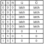
The image above is a truth table for the circuit
Q not is 1: pause
Q not is 0: un pause