3-Inch LED Digital Clock Using PIC16F628A, DS1302 & DS18B20
by LongTechnical in Circuits > Clocks
24 Views, 0 Favorites, 0 Comments
3-Inch LED Digital Clock Using PIC16F628A, DS1302 & DS18B20

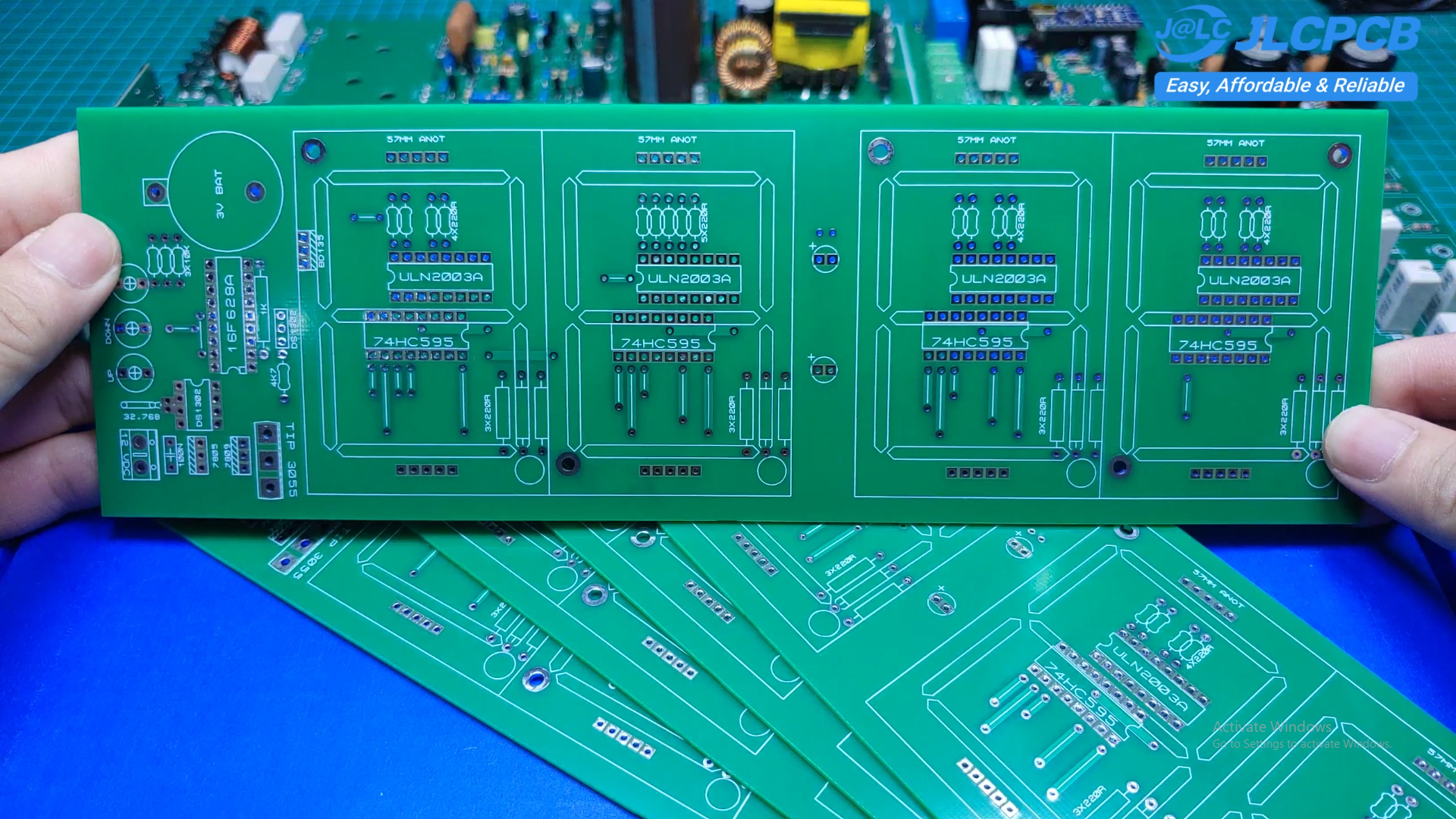
In this project, I'll show you how to build a 3-Inch 4-Digit LED Digital Clock using the PIC16F628A microcontroller. The clock displays the current time on large 3-inch common-anode seven-segment LEDs, making it easy to read from a long distance. The PCB for the project was ordered from JLCPCB.
In addition to displaying the time, the clock can also measure ambient temperature using the DS18B20 digital temperature sensor. The DS1302 Real-Time Clock (RTC) keeps accurate time, while a CR2032 backup battery preserves the time even during power outages.
The display is driven by 74HC595 shift registers and ULN2003A driver ICs, allowing the entire circuit to be controlled with only a few I/O pins from the PIC16F628A.
This project is ideal for beginners and electronics enthusiasts who want to learn about PIC microcontrollers, RTC communication, digital temperature sensors, and LED display driving.
Supplies
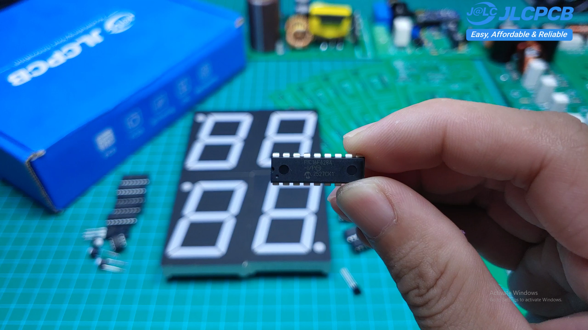
Features
- Large 3-inch 4-digit LED display
- PIC16F628A microcontroller
- DS1302 Real-Time Clock
- DS18B20 digital temperature sensor
- Time backup using CR2032 battery
- Time adjustment using push buttons
- 74HC595 shift registers for I/O expansion
- ULN2003A drivers for LED current sinking
- Simple and low-cost components
- Easy to assemble
- PCB for the project was ordered from JLCPCB by upload Gerber file here to JLCPCB website
Components Required
- PIC16F628A
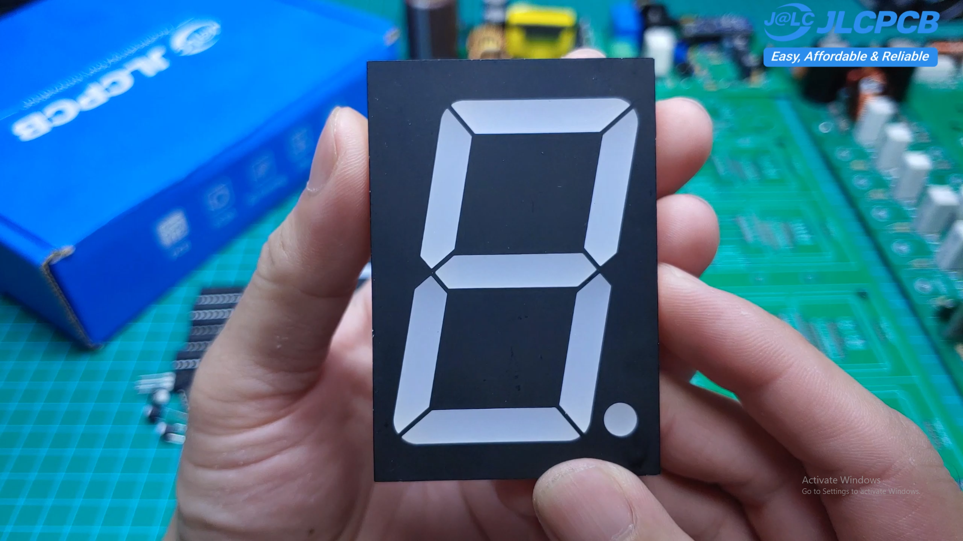
- 4 × 3-inch Common Anode 7-Segment LEDs
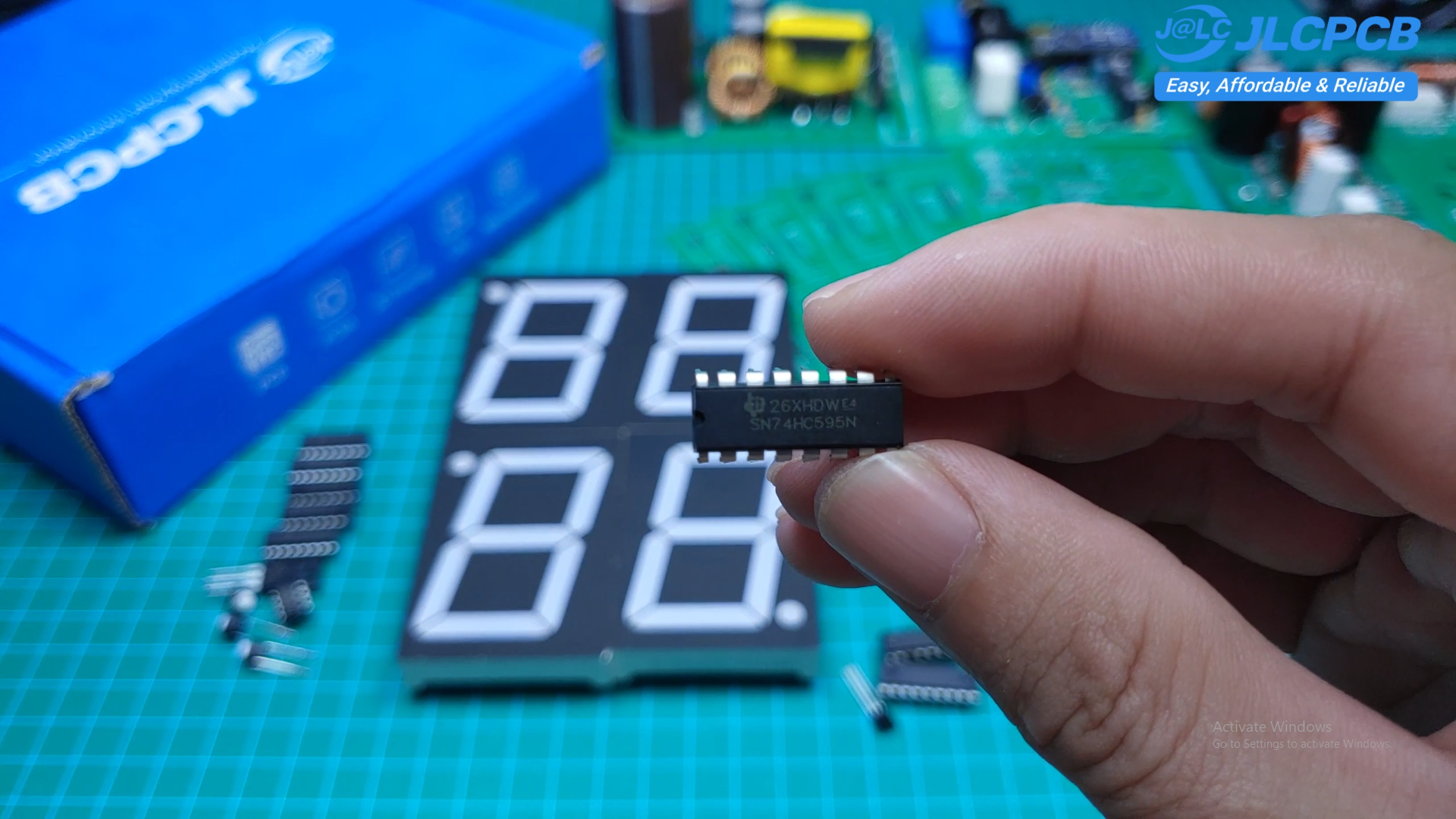
- 4 × 74HC595
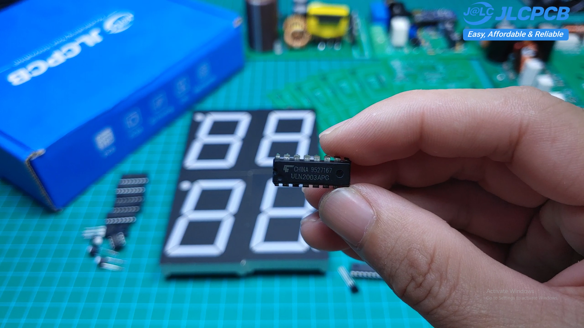
- 4 × ULN2003A
- DS1302 RTC
- DS18B20 Temperature Sensor
- CR2032 Battery Holder
- 5V Voltage Regulator
- 9V LED Supply Circuit
- Push Buttons
- Crystal Oscillator
- Capacitors
- Resistors
- PCB
How It Works
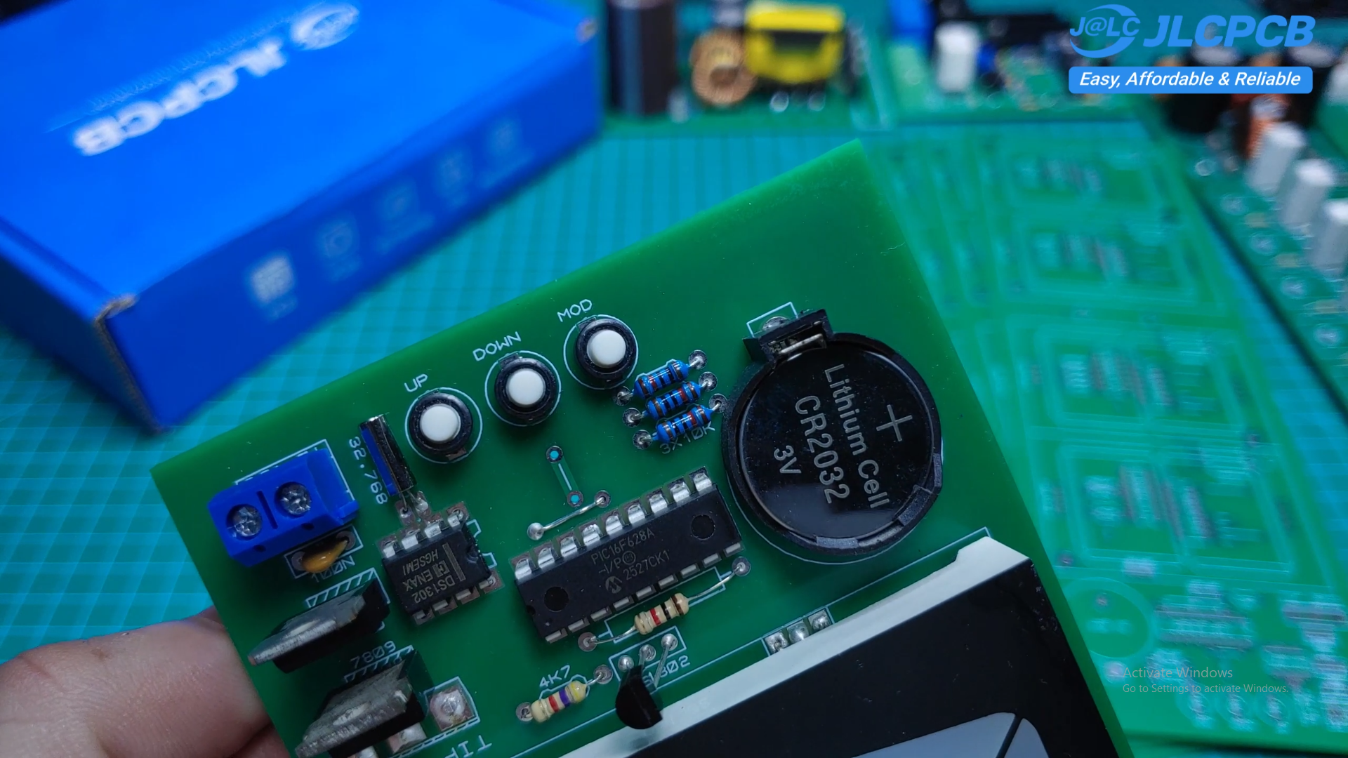
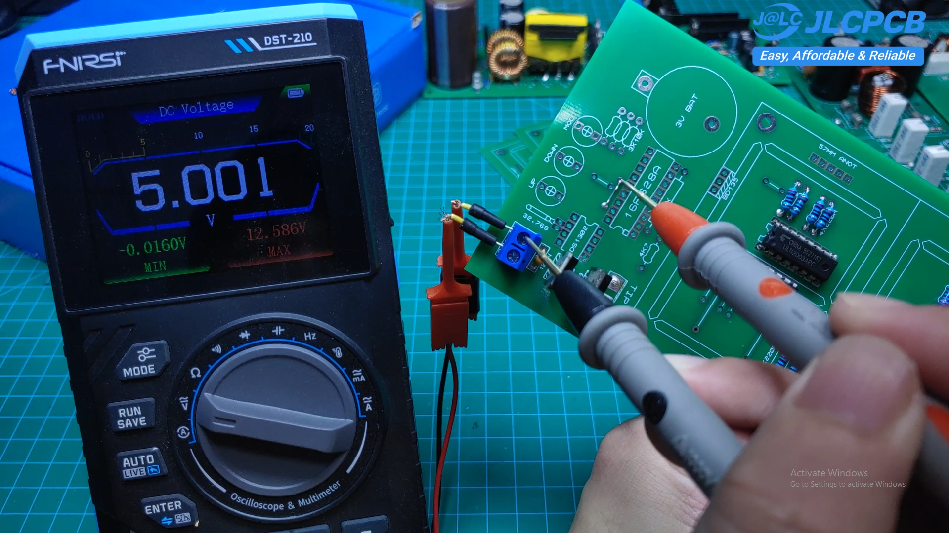
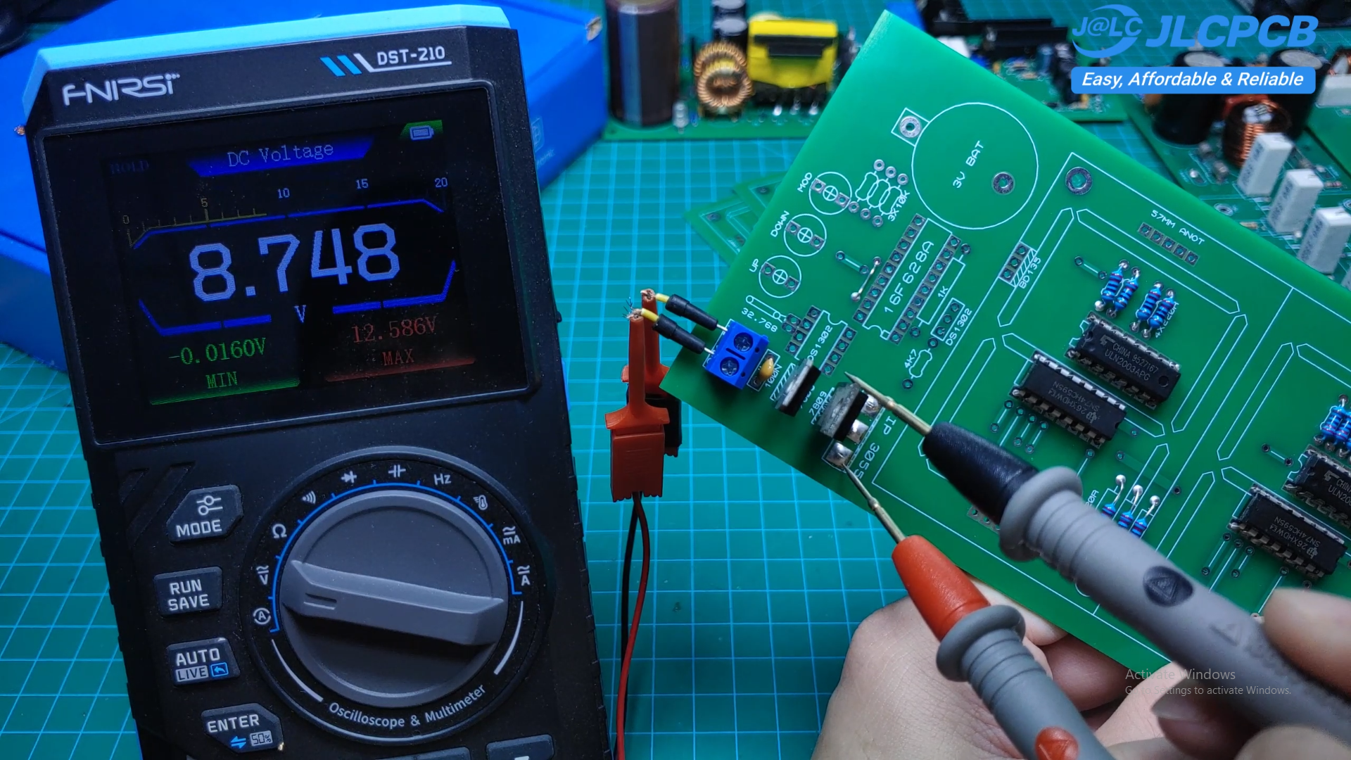
The PIC16F628A controls the entire system. It communicates with the DS1302 to read and write the current time and reads the temperature from the DS18B20 sensor.
The seven-segment LEDs are controlled through four 74HC595 shift registers, while four ULN2003A ICs provide the required current sinking for the display.
The circuit uses two power rails:
- 5V for the microcontroller and logic circuits
- 9V for the large LED display
A CR2032 battery keeps the RTC running whenever the main power is disconnected.
Assembly
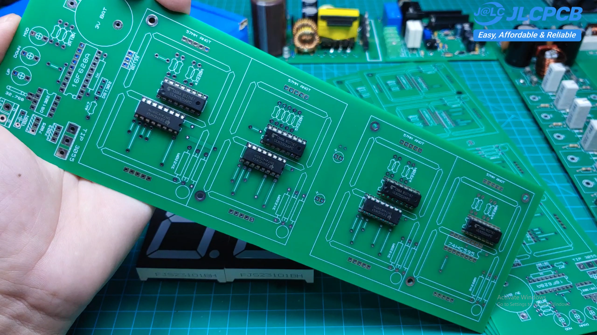
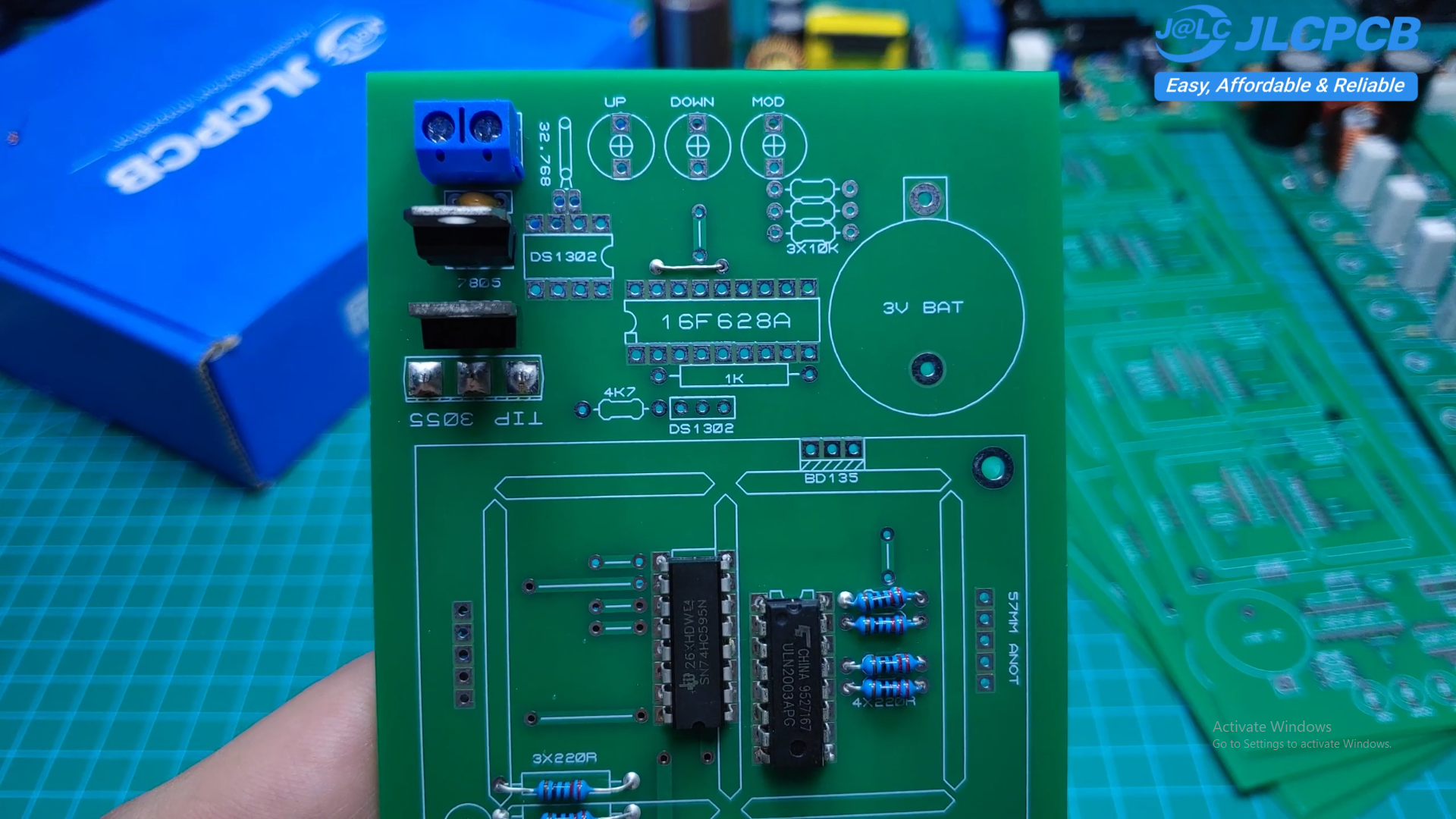
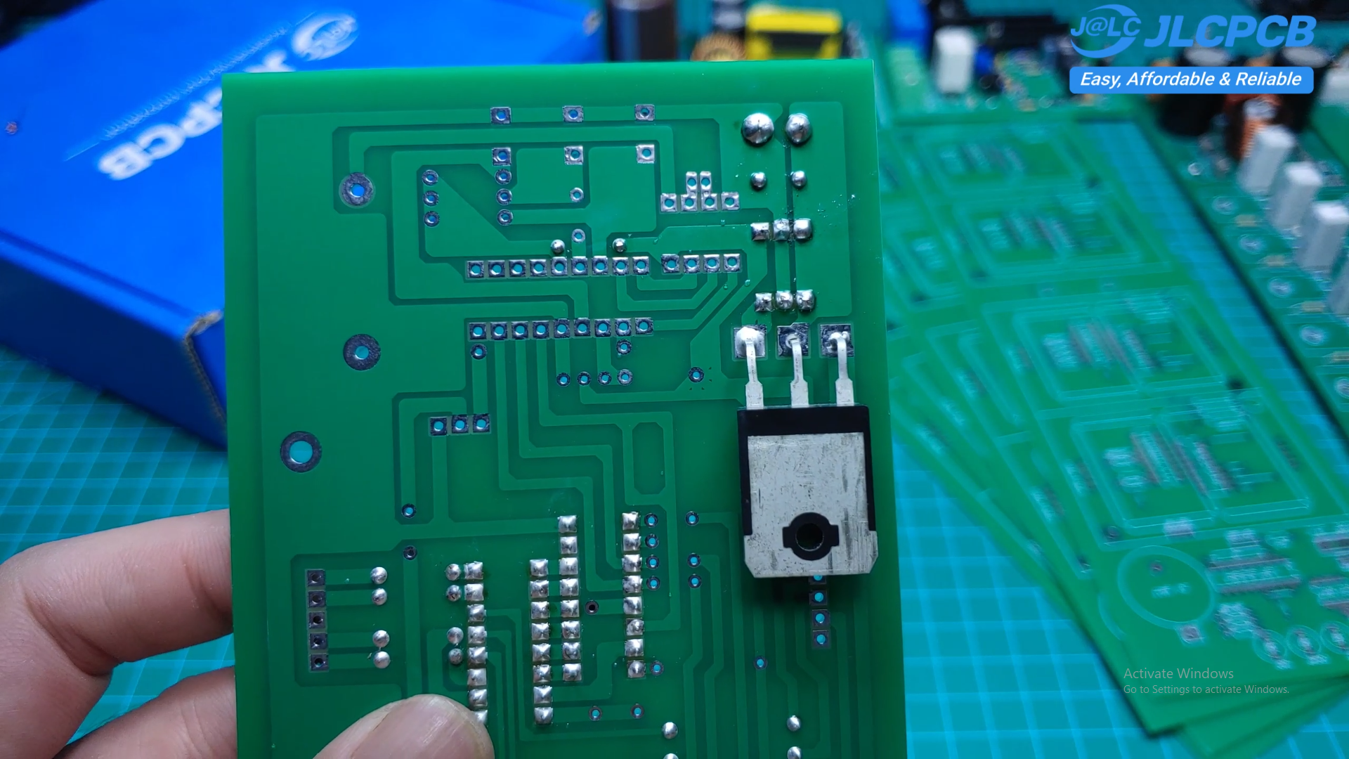
Start by soldering the 74HC595 and ULN2003A ICs since they are located beneath the LED displays.
After assembling the remaining components, verify both the 5V and 9V power supplies before installing the PIC16F628A.
Finally, solder the four 3-inch LED displays. Make sure the decimal points are facing downward.
Setting the Time
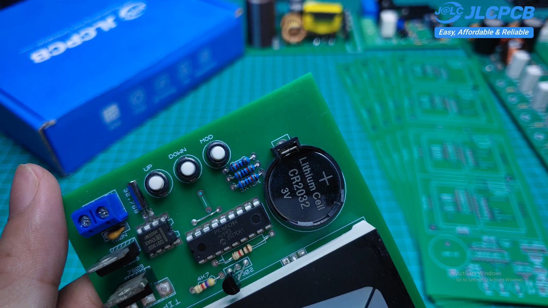
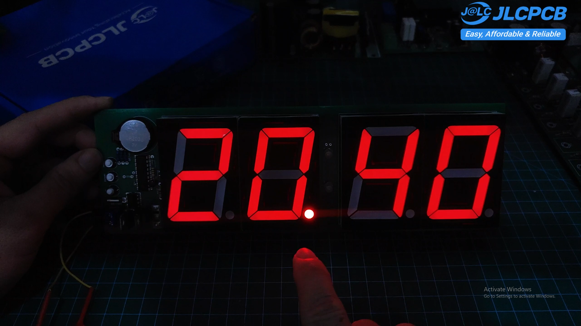
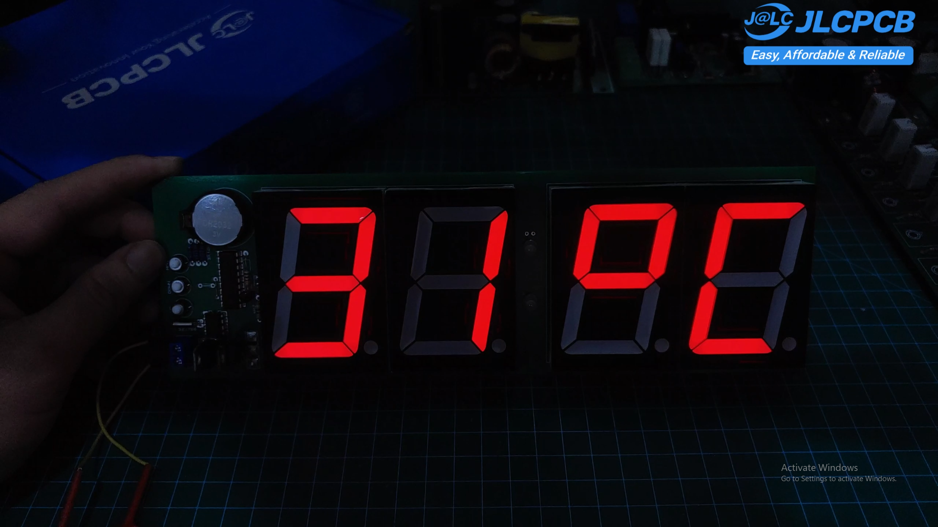
When powered on for the first time, the displayed time may not be correct.
Press the MODE button to enter the setting mode.
- Adjust the hour using the UP and DOWN buttons.
- Press MODE again to adjust the minutes.
- Press MODE one more time to save the settings.
The DS1302 will retain the correct time even if the main power is removed.
Files Included
- HEX File.
- PCB Gerber Files.
- PCB.
This project demonstrates how to build a large, easy-to-read LED digital clock using inexpensive and widely available components. It is a great project for learning PIC programming, RTC communication, shift registers, and digital temperature sensing.
If you build this project, I'd love to see your results. Feel free to share your photos or improvements in the comments.
Happy building!