3 LED Whac-A-Mole Game With Arduino and LCD
by 785260 in Circuits > Arduino
60 Views, 0 Favorites, 0 Comments
3 LED Whac-A-Mole Game With Arduino and LCD
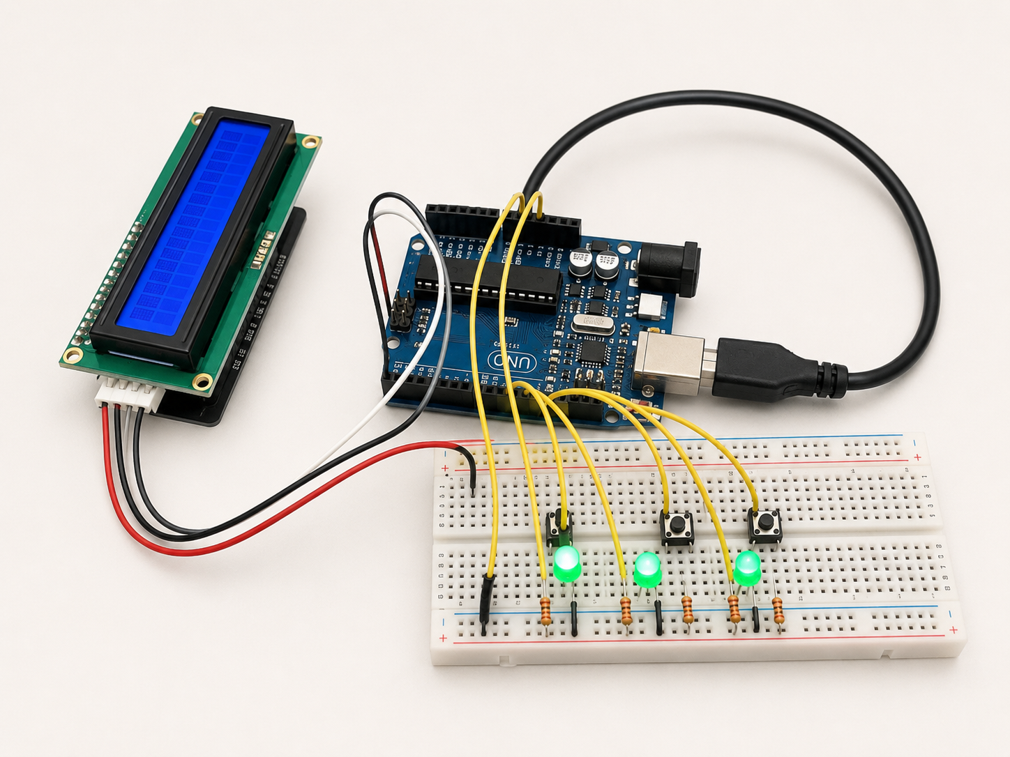
For this project, I made a 3 LED reflex game using an Arduino, three LEDs, three pushbuttons, and an I2C LCD screen. The goal of the game is to test the player’s reaction speed. A random LED turns on, and the player has to press the matching button before time runs out.
The LCD displays the round number, score, instructions, and final result. This makes the project more interactive because the player can see feedback such as “Nice hit!”, “Too slow!”, and “Game Over.” I chose this project because it uses both inputs and outputs. The pushbuttons act as inputs, while the LEDs and LCD act as outputs.
Downloads
Supplies
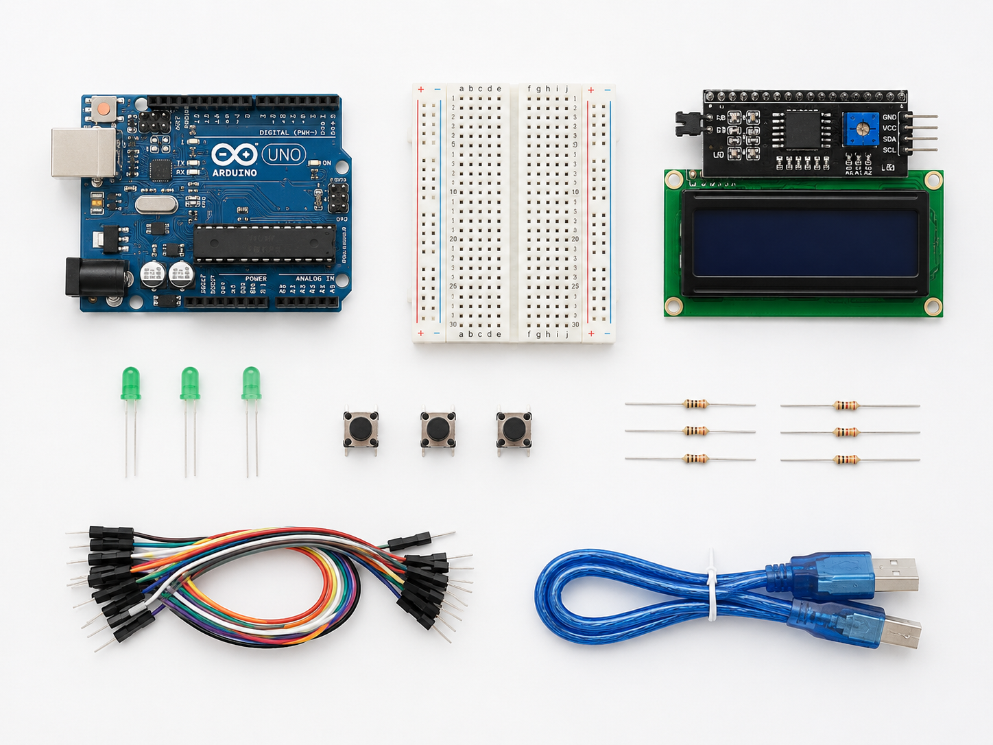
For this project, I used:
- Arduino Uno or compatible Arduino board (1)
- Breadboard (1)
- LEDs (3)
- Pushbuttons (3)
- 330 ohm resistor (3)
- 1k ohm resistor (3)
- 16x2 LCD screen with I2C backpack
- Jumper wires
- USB cable for Arduino
- Computer with Arduino IDE installed
The I2C LCD only needs four wires: GND, VCC, SDA, and SCL. This made it easier to add a screen without using too many Arduino pins. The LEDs were used to show which button the player should press, and the pushbuttons were used as the player’s input.
Wire the LEDs
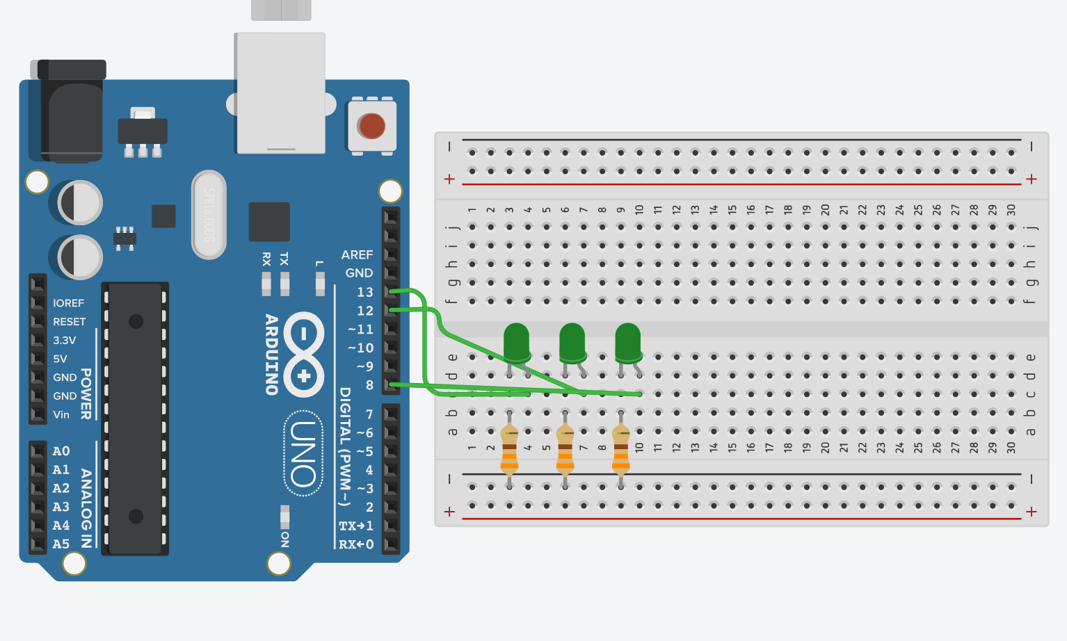
First, place three LEDs on the breadboard. Each LED needs to be connected to an Arduino digital pin and to ground through a resistor.
The LED pin connections are:
- LED 1 (Anode) to Arduino Pin 13
- LED 2 (Anode) to Arduino Pin 12
- LED 3 (Anode) to Arduino Pin 8
Then to each cathode, connect a 330 ohm resistor.
For each LED, connect the longer leg to the Arduino pin. Connect the shorter leg to a resistor, then connect the resistor to ground. The resistor helps protect the LED by limiting the current.
After wiring the LEDs, test them with a simple blink code or by turning them on one at a time. This makes sure the LEDs are connected properly before adding the buttons and LCD.
Wire the Pushbuttons
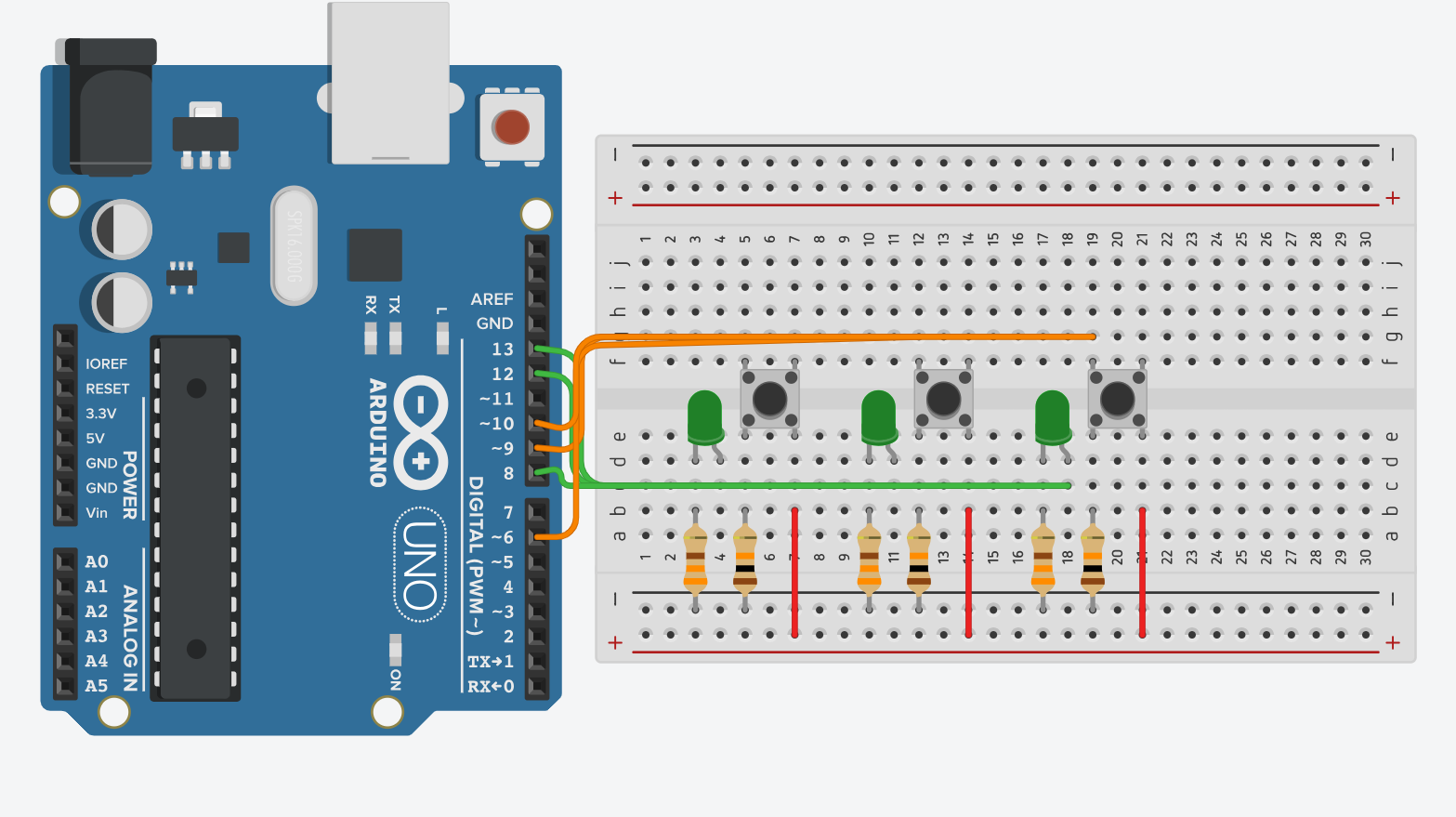
Next, place three pushbuttons on the breadboard. Each pushbutton is used to match one of the LEDs in the game. When an LED turns on, the player has to press the correct button.
The button pin connections are:
- Button 1 to Arduino Pin 9
- Button 2 to Arduino Pin 6
- Button 3 to Arduino Pin 10
Each button also needs a resistor so the Arduino can clearly tell if the button is being pressed or not. One side of the button should be connected to 5V, and the other side should connect to the Arduino input pin. From that same input side, connect a resistor to ground. This makes the button read LOW when it is not pressed and HIGH when it is pressed.
After wiring the buttons, test them before adding the full game code. A simple test can be used to check if pressing each button changes the input value. This helps make sure the buttons are working properly before adding the LCD and game logic.
Wire the LCD Screen
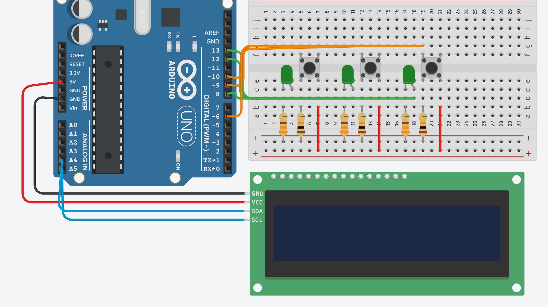
After wiring the LEDs and buttons, connect the LCD screen. This project uses a 16x2 LCD with an I2C backpack, which makes the wiring easier because it only needs four wires.
The LCD connections are:
- LCD GND to Arduino GND
- LCD VCC to Arduino 5V
- LCD SDA to Arduino A4
- LCD SCL to Arduino A5
The LCD is used to display the game information, such as the round number, score, instructions, and final result. Since the LCD uses I2C communication, it only needs the SDA and SCL pins instead of many digital pins.
Upload the Code
After the circuit is wired, upload the Arduino code. The code randomly chooses one of the three LEDs. The matching LED turns on, and the LCD tells the player which button to press. If the player presses the correct button in time, the score increases. If the player is too slow, the LCD shows “Too slow!”
Paste this code into the Arduino IDE:
#include <Wire.h>
#include <LiquidCrystal_I2C.h>
LiquidCrystal_I2C lcd(0x27, 16, 2);
int button1 = 9;
int button2 = 6;
int button3 = 10;
int led1 = 13;
int led2 = 12;
int led3 = 8;
int score = 0;
void setup() {
lcd.init();
lcd.backlight();
pinMode(button1, INPUT);
pinMode(button2, INPUT);
pinMode(button3, INPUT);
pinMode(led1, OUTPUT);
pinMode(led2, OUTPUT);
pinMode(led3, OUTPUT);
randomSeed(analogRead(A0));
lcd.clear();
lcd.setCursor(0, 0);
lcd.print("3 LED Reflex");
lcd.setCursor(0, 1);
lcd.print("Game Starting");
delay(2000);
}
void loop() {
score = 0;
for (int round = 1; round <= 10; round++) {
turnOffLEDs();
int randomLED = random(1, 4);
lcd.clear();
lcd.setCursor(0, 0);
lcd.print("Round ");
lcd.print(round);
lcd.print("/10");
lcd.setCursor(0, 1);
lcd.print("Score: ");
lcd.print(score);
delay(800);
lcd.clear();
lcd.setCursor(0, 0);
lcd.print("Press Button ");
lcd.print(randomLED);
lcd.setCursor(0, 1);
lcd.print("Score: ");
lcd.print(score);
if (randomLED == 1) {
digitalWrite(led1, HIGH);
}
if (randomLED == 2) {
digitalWrite(led2, HIGH);
}
if (randomLED == 3) {
digitalWrite(led3, HIGH);
}
int correct = 0;
for (int i = 0; i < 200; i++) {
if (randomLED == 1 && digitalRead(button1) == HIGH) {
correct = 1;
break;
}
if (randomLED == 2 && digitalRead(button2) == HIGH) {
correct = 1;
break;
}
if (randomLED == 3 && digitalRead(button3) == HIGH) {
correct = 1;
break;
}
delay(10);
}
turnOffLEDs();
if (correct == 1) {
score++;
lcd.clear();
lcd.setCursor(0, 0);
lcd.print("Nice hit!");
lcd.setCursor(0, 1);
lcd.print("Score: ");
lcd.print(score);
waitForButtonsReleased();
delay(900);
}
else {
lcd.clear();
lcd.setCursor(0, 0);
lcd.print("Too slow!");
lcd.setCursor(0, 1);
lcd.print("Score: ");
lcd.print(score);
delay(900);
}
}
lcd.clear();
lcd.setCursor(0, 0);
lcd.print("GAME OVER");
lcd.setCursor(0, 1);
lcd.print("Final: ");
lcd.print(score);
lcd.print("/10");
delay(5000);
}
void turnOffLEDs() {
digitalWrite(led1, LOW);
digitalWrite(led2, LOW);
digitalWrite(led3, LOW);
}
void waitForButtonsReleased() {
while (digitalRead(button1) == HIGH ||
digitalRead(button2) == HIGH ||
digitalRead(button3) == HIGH) {
delay(10);
}
}
To get the libraries for our specific LCD, you will need to go on google and search up LCD I2C library by Frank de Brabander, download this library and upload it into your code as a zip file.
Test the Game
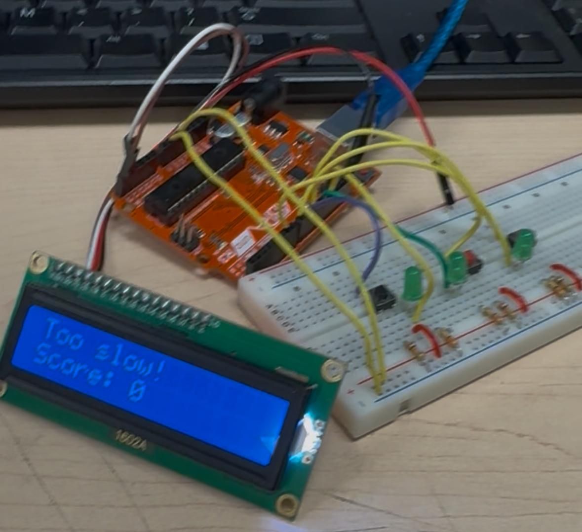
Once the code is uploaded, the LCD should show “3 LED Reflex” and “Game Starting.” Then the game begins. One LED will turn on, and the LCD will tell the player which button to press.
If the correct button is pressed, the LCD shows “Nice hit!” and the score increases. If the player does not press the button quickly enough, the LCD shows “Too slow!” After 10 rounds, the LCD shows the final score out of 10.
Downloads
Troubleshooting
If the LCD does not work, check that GND, VCC, SDA, and SCL are connected correctly. On an Arduino Uno, SDA is A4 and SCL is A5.
If a button does not work, check that it is pushed fully into the breadboard and that the resistor is connected properly. If the button works backwards, the code may need to check for LOW instead of HIGH.
If an LED does not turn on, check that the LED is facing the correct direction. The longer leg should connect to the Arduino pin, and the shorter leg should connect through a resistor to ground.
Conclusion
The final project is a working reflex game that uses digital inputs and outputs. The buttons are the inputs, while the LEDs and LCD are the outputs. The Arduino controls the game by randomly choosing LEDs, checking button presses, keeping score, and displaying messages on the LCD.
This project helped me learn how to use pushbuttons, LEDs, random numbers, and an I2C LCD in one circuit. A future improvement would be to add more LEDs, a buzzer, a timer, or a difficulty setting that makes the game faster each round.