$3 Roomba 500 Bluetooth Adapter
by arpruss in Living > Cleaning
4871 Views, 28 Favorites, 0 Comments
$3 Roomba 500 Bluetooth Adapter


With a Bluetooth adapter, one can operate a Roomba with a phone or other device, write software that interacts with it, etc.
My previous Roomba Bluetooth adapter was self-powered, with a battery, which was a nuisance, so I decided to make a new one powered by the Roomba itself, especially since component prices have gone down. Here are the components you need, with current pricing (when I bought them, I paid some more cents):
- Mini DIN 7 plug ($0.99 on ebay; search for mini din 7)
- SPP-C Bluetooth module ($1.32 on Aliexpress; I went for the cheaper and smaller module without a breakout board; they have soldering holes on the side, and are quite easy to solder)
- Mini360 adjustable buck converter ($0.39 on Aliexpress)
Total: $2.70.
Optional, but if you have them on hand it'll make the project nicer:
- small red LED ($0.54 for 100 from Aliexpress)
- 1K resistor ($0.58 for 100 from Aliexpress)
- some sort of case (I made a 3D printed one, with liberal use of hot glue for mounting)
Tools:
- soldering iron
- hot glue gun (or some other goopy adhesive)
- multimeter
- Arduino Uno or Mega, or some other UART-to-USB bridge for initial setup of the Bluetooth module (a ch340 will add $0.54 to the project; I suppose you could even use a second SPP-C via Bluetooth)
- computer
- small screwdriver to adjust buck converter
Prepare SPP-C Module for Baud Rate Adjustment

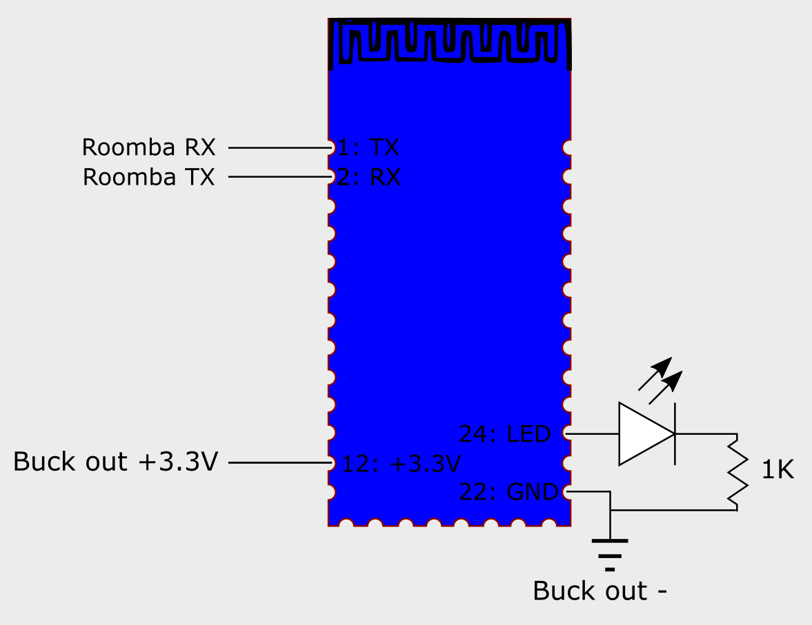
Solder wires to the SPP-C module's GND (pin 22), +3.3V (pin 12), RX (pin 2) and TX (pin 1) connections. (See photo of top view.) This is easier than it seems, but you'll want to use a third hand to hold the wires to the connections while soldering.
Don't connect the other ends of the wires yet.
Optionally, put an LED and a 1K resistor between pin 24 (plus side of LED) and ground.
Set Baud Rate


Put a jumper between Ground and Reset on your Arduino to make your Arduino function like a UART-to-USB converter. But note that the Arduino's RX/TX pins will function as TX/RX pins in this mode.
Alternately, use a standalone UART-to-USB converter, but then you'll also need to find a 3.3V power supply.
Join:
- Bluetooth module RX to Arduino RX or UART converter TX
- Bluetooth module TX to Arduino TX or UART converter RX
- Bluetooth module GND to Arduino or power supply Ground
- Bluetooth module 3.3V to Arduino or power supply 3.3V
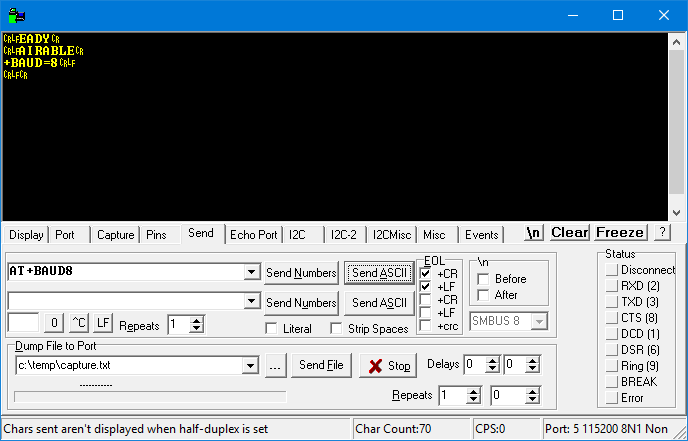
Make sure you have a terminal emulation program on your computer. I use Realterm.
Attach the Arduino or UART converter to your computer. If you have an LED attached to the SPP-C, it should be slowly flashing.
Connect to your Arduino/UART serial port at 9600 baud.
You should see some text from the SPP-C, though it might not be fully legible. If nothing is seen, something's wrong.
Send the following commands, with a CR LF after each. You need to type these commands very quickly, so either use your terminal emulator's Send ASCII command, or copy and paste:
AT+BAUD8
AT+NAMERoombaBridge
(You can give some other name if you prefer.)
Open Up MiniDIN-7 Connector


Open up the MiniDIN-7 connector to be able to access the solderable upper portions of the pins. I also trimmed the metal shielding to allow for a lower profile.
Remove Roomba Top Plate


Remove Roomba top plate to expose the MiniDIN female socket. I drilled a hole in the top plate so that in the future I wouldn't have to remove the plate.
Connect Buck Converter to Roomba and Adjust

Solder wires from the buck converter's IN+ and IN- connections to the MiniDIN's Roomba battery + and battery ground connections.
Plug MiniDIN into Roomba.
Attach a multimeter to the buck converter's OUT+ and OUT- connections. Set the multimeter to measure voltage in a range of about 0-10V. Turn the set screw on the buck converter to get close to 3.3V.
Connect Bluetooth Module


Unplug MiniDIN. Connect the Roomba RX line (see the top-view photo of the Roomba socket) to the SPP-C's TX line and the Roomba TX line to the SPP-C's RX line. Connect the buck module's OUT+ and OUT- to the SPP-C 3.3V and GND lines, respectively.
Try


Plug MiniDIN into Roomba.
Pair the SPP-C with your computer, tablet or phone. The PIN should be 1234.
Use a Roomba remote control app. On Android, I find Roomba touch drive to be pretty reliable. There is also my own Roodrive which shows a window on top of other apps, which lets you have first-person view if you put a webcam on the Roomba and use a Webcam viewer on the Android device (here's my Instructable for that).
Finishing Touches


Once it works, I would put some hot glue on the connections to keep them from getting loose or coming in contact.
I'd also put everything in some sort of a case. I 3D printed a case that is open on the underside from translucent plastic so the LED could be seen, and mounted stuff inside with generous use of hot glue. Here are the printable files.