3-in-1 Solar-Operated Agricultural Sprayer – Product Design
by BhushanKhollam in Workshop > Solar
55 Views, 0 Favorites, 0 Comments
3-in-1 Solar-Operated Agricultural Sprayer – Product Design
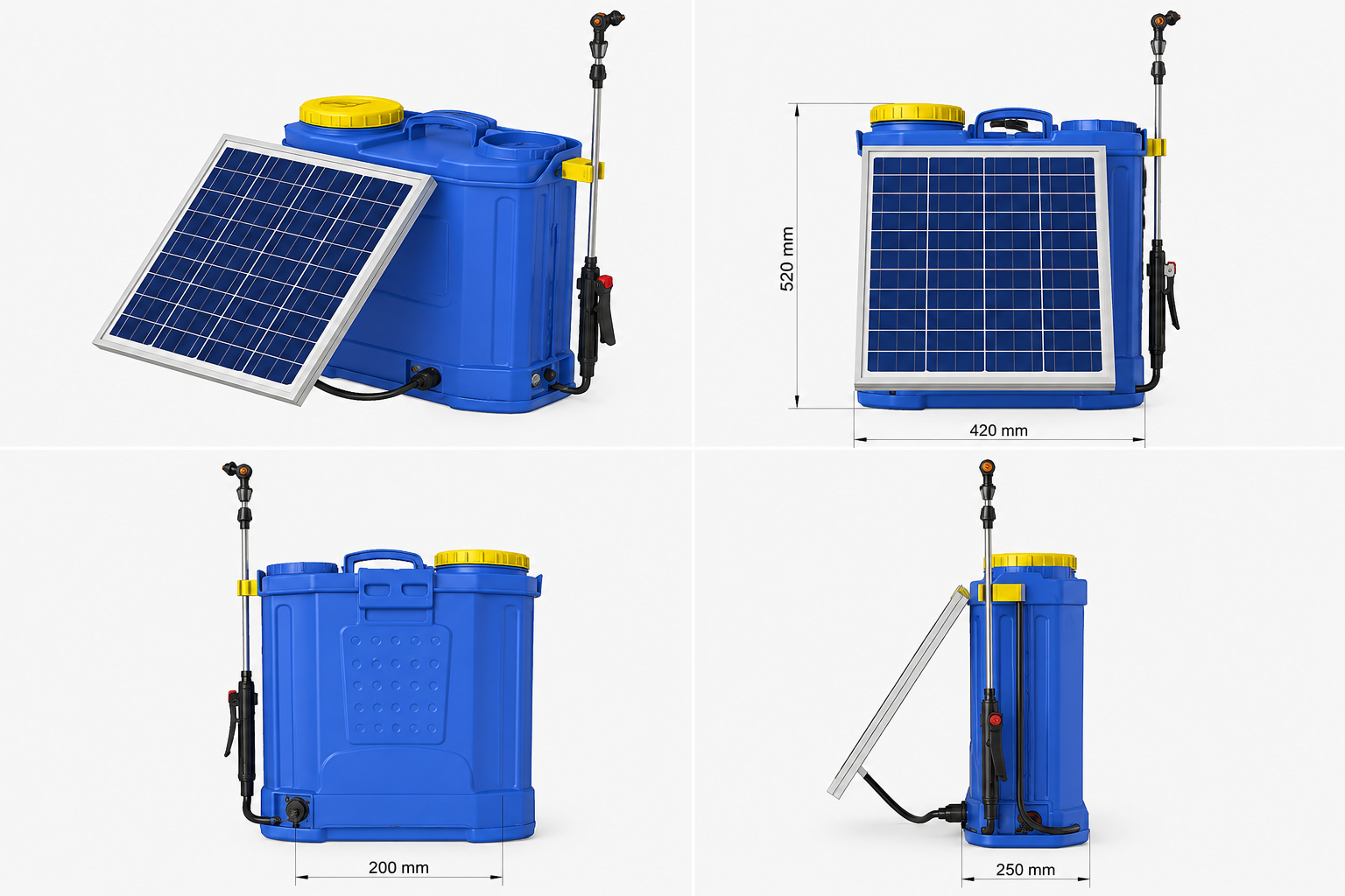
The 3-in-1 Solar-Operated Agricultural Sprayer is a product-design project focused on developing a portable agricultural spraying system with three operating power options: solar energy, rechargeable battery power, and manual hand-pump operation.
The main objective was to reduce dependence on fuel-powered spraying systems while providing a reliable backup mechanism for agricultural applications, particularly where electrical infrastructure may be limited.
The product was developed using a mechanical product-development approach, including requirement definition, concept development, CAD modeling, assembly design, interference checking, design review, and Design for Manufacturing (DFM) considerations.
The design concept includes a 15 L tank, 20 W solar panel, 12 V 7.2 Ah rechargeable battery, and a target operating pressure of 2.0–4.5 bar.
About the Designer
I am Bhushan Khollam, a Mechanical Engineering student interested in 3D CAD modeling, product design, DFM/DFA, GD&T, and manufacturing-oriented engineering.
Supplies
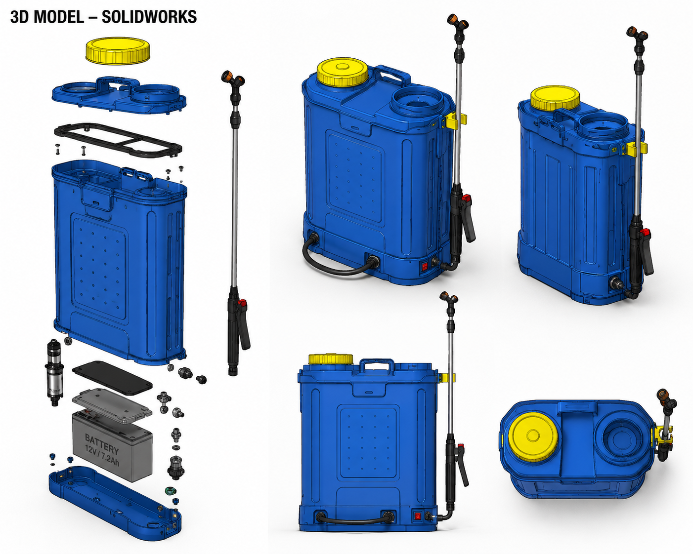
CAD & Design
- SolidWorks
- 3D CAD modeling software
- Engineering drawing tools
- Product assembly and visualization tools
Main Product Components
- 15 L agricultural sprayer tank
- 20 W solar panel
- 12 V, 7.2 Ah rechargeable battery
- Electric pump
- Manual hand pump
- Spray hose
- Spray lance
- Adjustable spray nozzle
- Battery enclosure
- Solar-panel mounting bracket
- Structural/support components
- Fasteners and fittings
- Electrical switches and wiring
Materials / Manufacturing Considerations
- HDPE for the main tank
- Plastic components
- Sheet-metal/fabricated support components
- Standard fasteners
- Commercially available pump and electrical components
Define Product Requirements
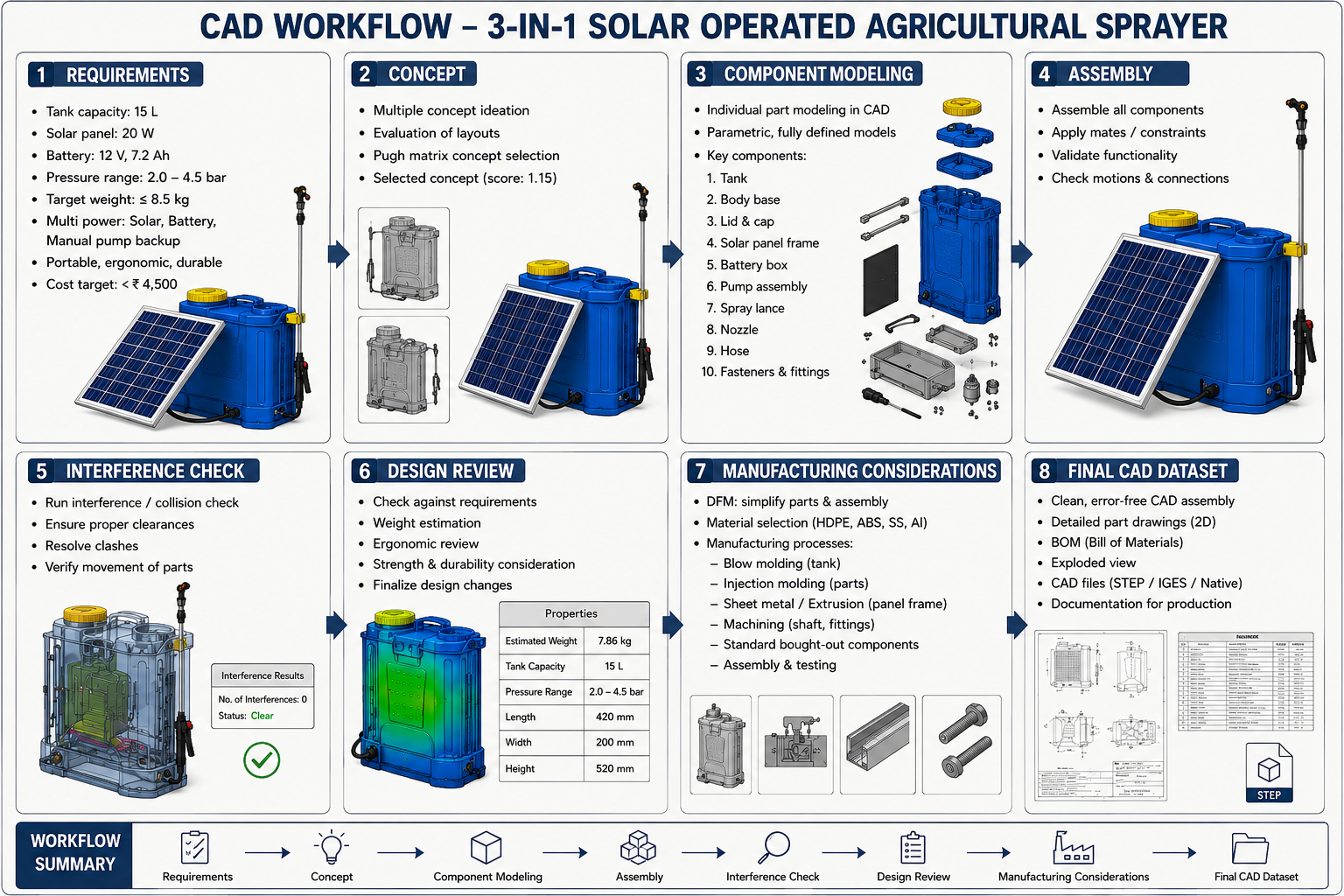
The first step was to establish the basic engineering requirements for the sprayer.
Key targets:
- Tank capacity: 15 L
- Solar panel: 20 W
- Battery: 12 V, 7.2 Ah
- Pressure range: 2.0–4.5 bar
- Target weight: ≤8.5 kg
- Three operating modes
- Portable and ergonomic design
- Target cost: below ₹4,500
The requirements were used as the foundation for the CAD design.
Develop & Select the Concept
Multiple product concepts were considered by varying the:
- Tank and component arrangement
- Solar-panel position
- Battery location
- Pump arrangement
- Spray-lance mounting
- User-accessible components
A weighted Pugh matrix was used to compare the concepts based on factors such as cost, weight, reliability, manufacturability, energy independence, and ergonomics.
The selected concept provided the best overall balance for the intended application.
Create the 3D CAD Components
The selected concept was converted into individual 3D CAD components.
The main modeled components included:
- Tank
- Tank lid/cap
- Base
- Solar-panel mount
- Battery enclosure
- Pump mounting
- Hose connections
- Spray lance
- Nozzle
- Manual-pump mechanism
- Fasteners and fittings
The components were developed with the intention of maintaining proper interfaces and assembly relationships.
Build the Complete Assembly
The individual components were brought together to create the complete sprayer assembly.
Assembly relationships were used to position:
Tank → Power System → Pump → Hose → Spray Lance → Nozzle
The solar panel, battery, pump, manual backup system, and spray components were integrated into the overall product layout.
The assembly was also reviewed for accessibility and practical component placement.
Perform Interference & Clearance Check
The complete CAD assembly was checked for potential interference between components.
Particular attention was given to:
- Internal component clearance
- Pump and battery placement
- Hose routing
- Spray-lance movement
- Fastener access
- Solar-panel mounting
- Tank and frame interfaces
Any identified clashes or insufficient clearances can then be corrected before moving toward prototype development.
Conduct Design Review
The assembled CAD model was reviewed against the original design requirements.
The review considered:
- Overall dimensions
- Weight distribution
- Portability
- Ergonomics
- Component accessibility
- Maintainability
- Structural arrangement
- Power-source integration
- Manufacturing feasibility
This stage helped refine the product before finalizing the design.
Apply DFM & Manufacturing Considerations
The design was evaluated using Design for Manufacturing and Assembly (DFMA) principles.
The focus was on:
- Reducing unnecessary part count
- Simplifying assembly
- Using standard fasteners
- Making components accessible
- Selecting suitable materials
- Designing practical mounting features
- Reducing manufacturing complexity
The HDPE tank was considered for its suitability for liquid storage, lightweight construction, and manufacturability.
Prepare the Final CAD Dataset
The final stage was to organize the product-development data into a professional CAD package.
The final dataset can include:
- Complete 3D assembly
- Individual part models
- Exploded assembly
- 2D engineering drawings
- Bill of Materials (BOM)
- Manufacturing information
- CAD exchange files such as STEP/IGES
- Product documentation
This creates a structured design package suitable for prototype development, design review, and future manufacturing consideration.