3D Printed Electromechanical 7-Segment Display
by tin-foil-hat in Circuits > Arduino
61999 Views, 421 Favorites, 0 Comments
3D Printed Electromechanical 7-Segment Display


I have always been enchanted by the old split-flap designs that used to fill train stations. With the modern digital era, we have lost some of the beauty of moving mechanical displays. The mechanical and tactile approach to displaying numbers and words is an interesting concept, and the clicking noise it makes is like nothing else. However, there are already plenty of people on the internet who have re-created these displays, and for that reason, I decided, why not re-invent a new mashup of mechanical displays?
I am an Australian self-taught young engineer who graduated high school this year and is enrolled in mechatronic engineering Uni next year. For this project, I decided to test all my skills, from custom PCBs to complex Fusion360 design, rendering and animation, film making, editing, programming in multiple languages, fundamental physics and computer networking.
Despite the complexities of this project, most people with a basic level of electronic understanding should be able to follow the steps laid out in the remainder of this Instructable. I have made this project as beginner-friendly as possible and coded easy-to-use graphical interfaces so that anyone should be able to attempt this. However, if you want to build this project and fully understand how it works, then you need a much more advanced understanding of electronics, circuits and programming.
Without further ado, let's begin!
Supplies


Most of the links below are to my preferred local electronics store, I have included them so that you can find additional information and dimensions about the parts I used so that you can find alternatives near you.
Tools:
- 3D printer
- Soldering iron + solder
- Flush cutters/Wire cutters
- Wire strippers
- Screwdriver (That matches your chosen M4 bolts & screws)
Materials:
- PLA filament (Two colours)
- Primary Colour: 104g per digit
- Secondary Colour: 3g per digit
- Other: 82g for the electronics case and 7g for 14 bolt washers and covers (per digit). You may choose to build a spooler (shown later) to help with winding coils which will use a small amount more filament - this is a tool and will not be a part of the final assembly
- PETG filament (One colour) - 4g per digit (This is used for a PCB clip, you can probably get away with using PLA if you don't have any PETG)
- Four Short M3 Screws (The exact length isn't important, these can be salvaged and are used for the electronics box)
- 5x2mm/5x3mm N50 Rare earth magnets (You need 7 per digit) - Example pack of 50 (The example pack says 5x3mm but they turned out to be 5x~2.4mm... make sure you measure whatever magnets you buy in person if possible. I would recommend buying 5x3mm magnets, but if they turn out to be a bit thinner, that is ok. If you buy 5x2mm magnets and they are thinner than advertised, they will be of no use)
- M4 40mm Zink Plated Bolts (You need 14 per digit, I couldn't buy 40mm so I bought 80mm bolts and cut them in half & welded the nut on one end - this is shown later)
- Masking tape/Electrical tape to protect the electromagnets we wind
- 0.1mm Enamelled copper wire (I salvaged mine as I didn't initially know this project was going to work, but I would highly recommend buying some) - Make sure you can solder this wire
- Superglue
Circuitry Components (Main controller):
- Link: Up to 8x 12v relays (You need one per digit)
- Link: Up to 8x 1N4004 diodes (You need one per relay)
- Link: One LD1117V33 & Matching heatsink + bolt + thermal paste
- Link: One 5mm coloured LED (Optional)
- Link: One 220Ohm resistor (Only needed if you include the LED above)
- Link: 3x ULN2803A Darlington Transistor Arrays (I highly recommend buying a pack of assorted ICs on Amazon as they are much cheaper)
- Link: 3x 18-pin IC Holder
- Link: 3x 74HC595 Shift Regesters
- Link: 3x 16-pin IC Holder
- Link: One NodeMCU ESP8266 (Note - the link is a pack of 2 but you only need 1)
- Link: One 100uF 63V Electrolytic Capacitor
- Link: One 10uF 63V Electrolytic Capacitor
- Link: 7x 0.1uF 50V Ceramic Capacitor
- Link: 2x 10K Resistors
- Link: One 3-way screw terminal
- Link: Straight Male pins (3x 8-way)
- Link: Female pins (2x 15-way)
Circuitry Components (Digit breakout board + 2x Joiner PCBs) - You need all this for every digit you make (Max 8 digits - unless you design an expansion board):
- Thin cable (Less than 1m per digit, used to connect electromagnetics internally)
- Link: 14x 1N5408 Diodes
- Link: 14x 1N4004 Diodes
- Link: Straight Male pins (2x 8-way for each joiner PCB - so 32 in total for both of them)
- Link: 90 Deg. Male pins (2x 2-way for the common anode connector and make-shift plug (I will explain this later))
- Link: ~21AWG wire for connecting the common anode back to the main controller (length is determined by how far away the digit is from the main electronics box)
- Link: Female pins (1x 2-way)
- Link: 1x 10K Resistor
- 15x Dupont female crimps (or similar to match housings)
- Dupont connector housings (or similar) - (1x1 for the common anode & 2x7 for the cathodes - I couldn't find a 2x7 so used a 2x6 and a 2x4 which I had on hand)
Additional Header Pins (This will change depending on what 'type' of digit it is - this is explained later)
- Standalone digit (Wires connected to both in & out)
- Straight Male Pins: 4x 8-way
- End digit (A digit that is next to one other, thus has wires connecting to either in or out)
- Straight Male Pins: 2x 8-way
- Female Pins: 2x 8-way (When you cut female pins you lose 1x pin, so you need a row of at least 17 pins)
- Middle digit (A digit that has another digit on both sides, thus has no wires connecting to it)
- Female Pins: 4x 8-way (When you cut female pins you lose 1x pin, so you need a row of at least 35 pins)
Other Electronics:
- 12v power supply (Minimum 1A)
- LM2596 Buck converter
- Link: ~21AWG wire for connecting the fuse, switch, buck converter etc. (~1m)
- Link: Fuse holder + Fuse (I am using a 2A fuse) - Doesn't have to be chassis mount as it is hidden inside the controller
- Link: One 2-way 2.54mm housing (for the fuse)
- Link: One 2-way 2.54mm 90 Deg. pin header (for the fuse)
- Link: SPST Switch
- Link: 8-way 2.54mm Crimp Housing (4x for the first digit, 1x for the relay connection, and if you run cables between digits (for example if you want a gap between them) you need 4x per gap)
- Link: 2.54mm Crimps (2x for the fuse, 32x for the first digit, 1x per digit for the relay connector, and if you run cables between digits you need 32x per gap)
- Link: 10 Wire IDC Cable (We only need 8 wires, so you can simply pull off 2 wires) - (This is to join the first digit to the main controller and any two digits that you choose to space apart (otherwise you can use the included PCBs to connect digits to each other), the length you need will differ depending on how far apart you want to space things)
- Heat shrink for protecting solder joins... or electrical tape if you are a caveman/cavewoman :)
Plan Out Your Displays
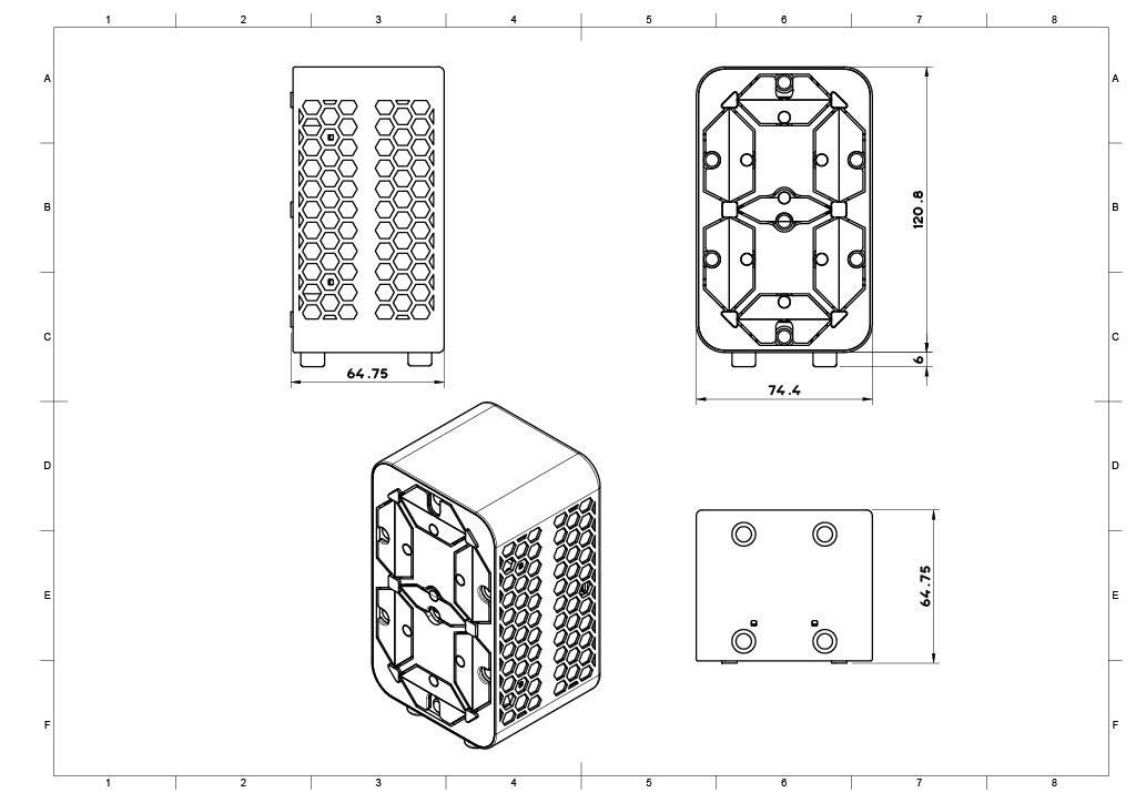

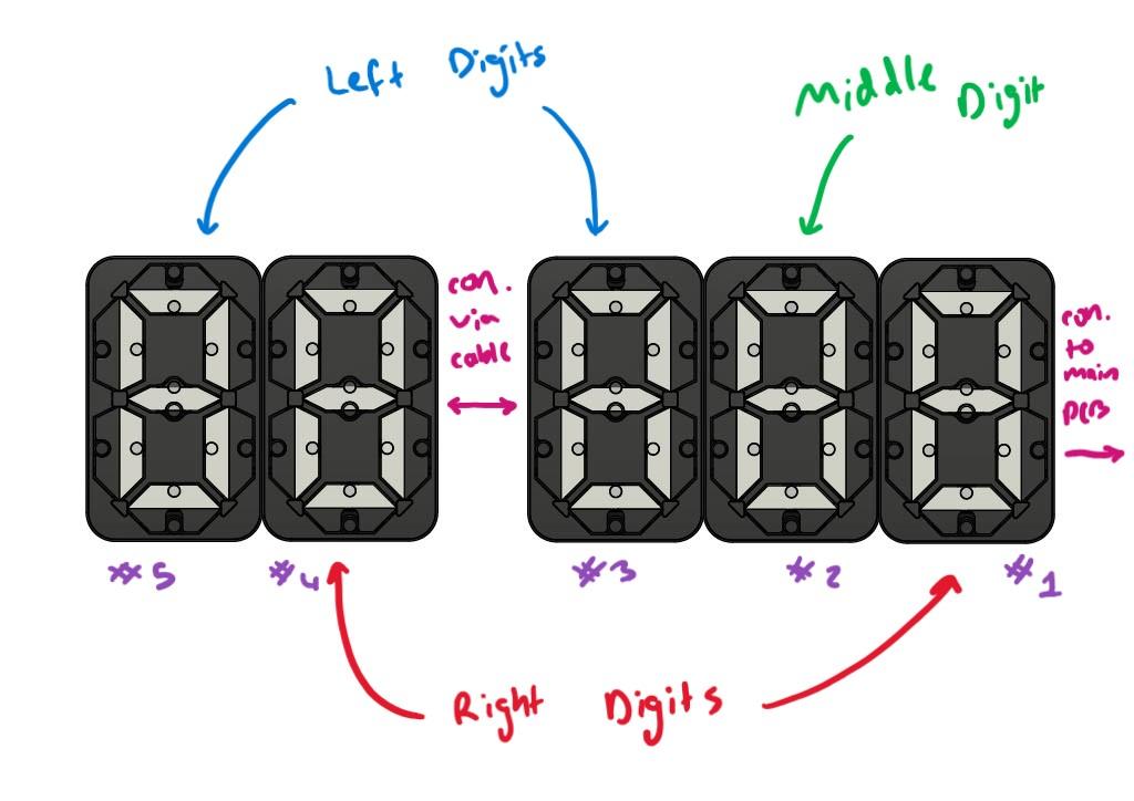
Before you rush into soldering and printing parts, you need to plan out your display(s). This will determine the lengths of cables and 'types' of digits you need to make. As you can see in the images above, there are 3 types of digits:
- Standalone/Solo digit (Wires connected to both in & out) - Not shown
- Left & Right end digits (A digit that is next to one other, thus has wires connecting to either in or out)
- Middle digit (A digit that has another digit on both sides, thus has no wires connecting to it)
The type of digit only changes the type of case you print, and the additional header pins needed. Digits that are next to each other are connected with a joiner PCB which I will touch on shortly, digits that are separated by a gap need to be connected with cables, and the first digit that connects back to the main controller needs to be connected with a cable.
PLEASE READ IF YOU ARE BUILDING A CLOCK
After designing these digits I decided to add a clock mode, which also meant adding a colon. This colon makes connecting the digits adjacent to it more difficult (as they are spaced further apart so a small joining PCB cannot bridge the gap). There are a few options here, but assuming that you have digits [4][3][Colon][2][1], the best option is to make digits 3 and 2 middle digits (like they normally would be) so that you can use the 3D printed plugs to connect the colon to both of them. You will need to make a cable to connect them to each other and this cable will need a DuPont connector (not 2.54mm crimp housing) as the middle digit has a narrower slot on the back. If you want the cables to sit flush, you will need to solder male header on the back of the digit-joining PCB on the side that is adjacent to the colon (as oppose to the normal female headers). Suppose you do use female headers like normal. In that case, you will have to make a male DuPont connecting cable, and this will stick out the back more than usual (In this case you could try to make your own connector that joins at 90deg using 90deg male headers or use prototyping perf-board to solder your own joining PCB).
How Do the Digits Work?
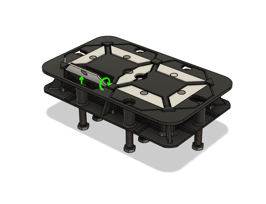

For those who are interested, I thought I'd break down how these digits work;
Each digit has a main centre panel with 14 electromagnets screwed into it. An electromagnet (as the name suggests) is a magnet that can be electrically controlled. Since any current-carrying conductor (in this case, the enamelled copper wire) generates a magnetic field, when we wind these around a soft iron core (in this case, the M4 bolts) and apply a current, the magnetic fields of each wire will concentrate and be directed in a uniform direction, creating a noticeable magnetic effect.
Each flap has a permanent magnet pressed into it, and these are attracted to the iron cores of the electromagnets even when no power is applied, meaning the overall power consumption is relatively low after a number/word has been displayed. When current flows in the correct direction through an electromagnet, it will generate an opposing magnetic pole (given two like poles; north-north or south-south will repel each other), and thus the magnet in the flap (and hence the flap itself) to be repelled from the electromagnet, and then the flap flips over.
This means that a microcontroller can determine and control which flaps need to be flipped to display a letter or number. However, since the electromagnets run on 12V at 500mA, a microcontroller such as the ESP8266 is unable to directly power the electromagnets. This is where we use the Darlington transistor arrays, which is simply an IC (integrated circuit) chip that contains 8 smaller transistors (which act like electronic switches in this case). This means that by using a lower voltage (of 3.3V from the ESP microcontroller) we can open/close (turn on or off) the 12V circuits that control the electromagnets.
However, that means for every digit we would need 14 digital IO (in-out) pins on our microcontroller! This is where multiplexing comes into play, which in simpler terms, is like building a grid. If you had a grid of 5x5 you have 25 possible "locations" in that grid despite only using 5+5 (10) pins! This is very similar to how we multiplex these digits. By joining all the anodes (positive wires) of the electromagnets in each digit, and then joining the corresponding 14 cathodes (negative wires) across digits, we effectively get a 14xN grid (where N is the number of digits you have). That way, we only need 1 more pin per digit added! It gets a bit confusing as we have 14 electromagnets, one that turns the flap "coloured" and one that turns it "black", rather than 7 where if it is "on" the flap is coloured, and "off" the flap is black. So if we (for example) wanted to turn the top flap on the first digit black we would power the (1, 1) "cell" in the "grid".
Despite only needing one extra digital IO pin per digit added, we still need to use at least 14 for all the cathodes. This means we use a shift register which for this project, just provides you with more digital IO pins. Since you can chain shift registers together, we can use 4 digital pins of our microcontroller and easily control 8 digits! Finally, we need to be able to open/close the circuit to the positive common anode of each digit. Unfortunately, the Darlington transistor arrays used in this project can only sink a pin to ground (aka negative) meaning that without additional components we can only pull pins low (aka to ground). This is fine for the 14 cathodes, but we need to use a relay (another type of electrical switch - but with moving parts) for each common anode. Thus the transistor can turn on or off the relay, which uses a mini internal electromagnet (yes... more electromagnets) to physically open or close a circuit.
Then with about 10,000+ lines of code, we can display some cool numbers and letters... wirelessly!!!
Print the Parts (No Multicolour Needed)

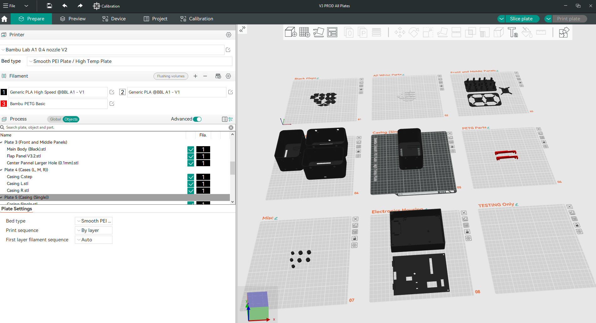


The first step is to print all the parts. Everything is printed in PLA except the PCB Clips which should ideally be printed in PETG. Make sure you test print a few parts to ensure they fit together otherwise, you will have a lot of post-processing to do (trust me... I made the mistake). You will also need to calibrate your 3D printer tolerances as some of the parts need them quite tight.
I would recommend choosing two colours that stand out from each other, in my case I chose black and white, but you could do black and green, purple and yellow, etc. The coloured flaps are really easy to swap out, meaning you can change your mind later on. For the remainder of this Instructable I will refer to the primary colour as "black" and the secondary colour as "white" as those are the colours that correspond to my digits.
I recommend printing both a white & black flap section to ensure the magnets fit and both sit flush with each other. I would also recommend printing the centre panel and inserting a flap by simply pushing it into place, it should flop around freely with very little resistance. Similarly, try screwing in one of the M4 bolts into a hole in the back of the centre panel, it should be tight, but easy enough to screw in by hand. Finally, test print a bolt cover and washer and test that they both slide snugly over an M4 bolt. If all of these parts fit nicely, then you should be ok to print the remaining parts.
Always test build your first digit before jumping into making lots to avoid silly mistakes and print failures due to incorrect tolerances.
You can find all the print files for free on Makerworld. If you use Orca slicer (or Bamboo slicer) I would highly recommend using the .3mf file as I have laid out all the parts on build plates for you and manually added support where needed. The white and black parts print separately so that people without multicolour printers can still build this project. More details about print settings can be found on Makerworld.
Order the PCBs


For this project, we also need two custom PCBs, one acts as a "digit breakout" board whilst the other is the "main controller" board. Every digit will need its own breakout board and you will only need one controller board overall. After looking around online I stumbled across PCBWay who manufacture affordable PCBs. Full disclosure, they sent me the PCBs free of charge, however, they are not paying me to promote their products. I was however pleasantly surprised at their quality of service and final product. It was comforting to know a qualified technician did a final check over the PCB given this was only my second ever custom PCB and I didn't want any glaring rookie mistakes. They reached out to clarify anything they were uncertain about rather than simply guessing and proceeding anyway, which I appreciated given my lack of conventional PCB design. The final PCBs turned up within a week, which is outstanding given shipping to Australia from overseas often takes upwards of 2-3 weeks. The final PCB quality was also amazing and they worked with no issues straight out of the box. They were also shipped in vacuum-packed bubble wrap which was comforting given the often rough handling of packages. Overall I was thoroughly impressed and I highly recommend their PCB-making service. Once again, thank you PCBWay for sending these to me free of charge.
You can find the Gerber files needed to upload to PCBWay on my GitHub page. If you do not know how to use GitHub, please refer to Step 17. You will only need 1 main controller board (although the minimum order quantity is 5) and depending on how many digits you plan on making you will need anywhere from 1 to 8 digit breakout boards. At the time, ordering 5 or 10 boards from PCBWay cost the same amount, so I opted to order 10 and my plan is to eventually build 6 digits.
Cut the Bolts (Skip If You Already Have 40mm M4 Bolts)


As mentioned in the Supplies step, I only had access to 80mm M4 bolts. If this is also the case for you, I found welding an M4 nut to one end and then using an angle grinder to cut the bolt in half worked well to make two 40mm M4 bolts. We don't need any M4 nuts so welding them to the bolt is no issue. Using a grinding wheel, belt sander or file to round over the cut ends will help you when installing these bolts at a later step.
Build a Spooler (Optional)


This is an optional step for those who plan to make a few digits or want to efficiently and accurately wind the electromagnetic coils. The spooler files are available on the Makerworld page. If you have access to a fast yet strong stepper motor, such as a NEMA 17, I would recommend modifying the spooler to use that, as it will be easier to count rotations and power, otherwise, you can use a DC motor paired with an IR sensor like me. First, insert a small DC motor into the casing (mine was salvaged from an old printer). Then gently push the IR sensor LEDs into the two holes located at the back of the motor mounting bracket. Then screw the bracket to a piece of scrap wood (if you cannot access one of the two screw holes due to the length of your motor, you will need to mount the bracket before inserting the motor). Then press on both the disk and coupler to the DC motor as shown in the images above. Depending on your light conditions, you will need to colour half of the disk white, you will see that one half has been recessed so that you can do it whilst also keeping it flush. I found snapping off the thinner half of the disk entirely worked best.
After the motor and IR sensor are mounted, screw on the servo housing and attach the servo motor. I found I needed the servo motor to be slightly lower than the DC motor due to the length of the servo horn, thus I mounted it on a separate piece of scrap wood and then mounted the DC motor's piece of wood on top.
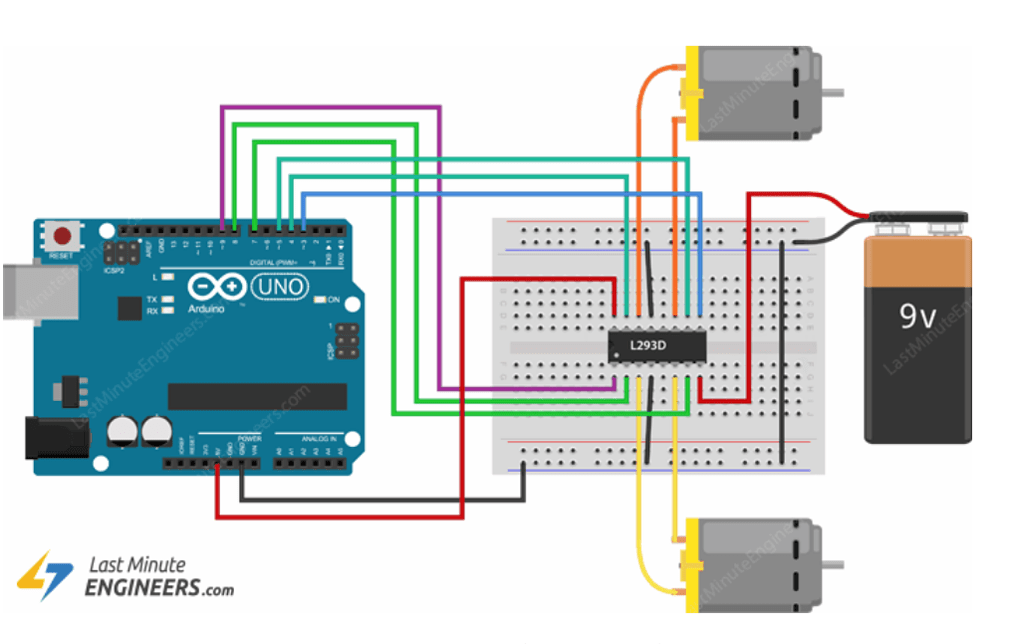
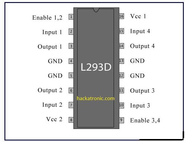
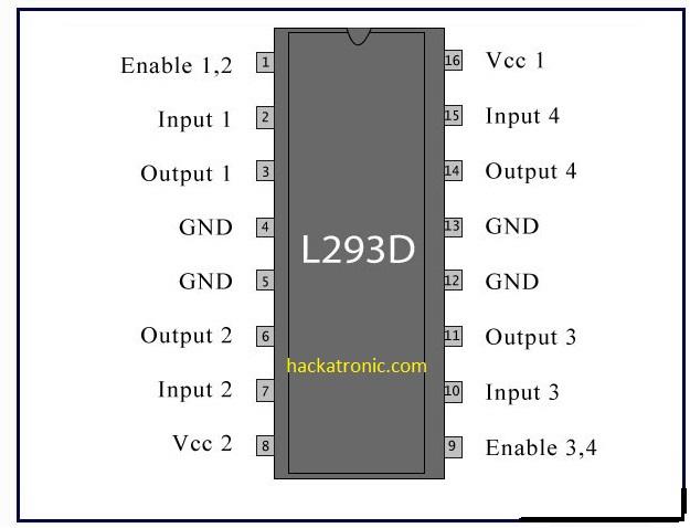
To wire everything, connect 5V and ground to the servo motor and IR sensor module where appropriate and then connect the servo data pin to the Arduino UNO's pin 9 and the IR data pin to the UNO's pin 2. Then use an L293D or similar H-bridge IC to connect the DC motor to an external 12V source as shown below (Credit: Last Minute Engineers). Since we only have one motor you only need to wire up one side of the H-bridge and you should connect the input wires as so; (Enable: pin 11), (Input 1: pin 4), (Input 2: pin 3) - You can refer to the pinout below (Credit: Hackatronics)

You can then upload the code found on GitHub to the Arduino Uno. If you do not know how to use GitHub, please refer to Step 17. By reading the README file, you can find out how to modify the number of turns of wire the spooler will wrap onto the bolt. If you do not already have Arduino IDE (or similar) for uploading the code, you can search online for instructions on how to install the latest version.
To use the spooler, first take one 40mm M4 bolt, one printed bolt cover, one printed bolt washer and the spooler bolt spacer. Insert the bolt cover, washer and then spacer (in that order) onto the M4 bolt, and then screw it into the shaft coupler that is already mounted to the DC motor. Then feed the copper wire through the server horn, and wrap it around the bolt a few times (leaving some excess sticking out). Then using a small piece of masking or electrical tape, stick down the coils so they don't come unraveled. Then stick the excess to the head of the bolt, such that it won't flap around as the bolt spins (this prevents it from getting tangled). Make sure the copper wire spool is free to spin, and then turn on the spooler. It will slowly accelerate and decelerate so that the wire isn't snapped, and the servo will help to maintain a level wind. After the spooler has finished making the electromagnet, use a larger piece of electrical tape/masking tape and fully wrap the coil. You can then remove the tape holding the excess to the head of the bolt, and unscrew it from the coupler. Finally, cut the copper wire still attached to the spool, once again leaving some excess to solder wires too.
Wind the Coils


To not overheat the Darlington transistor arrays used in this project, the max current draw of each coil must not exceed 500mA (so around 400 - 450mA to be safe). Using Ohms law, this means we need coils with a resistance of around 26.6 - 30.0 ohms (absolute minimum of 24 ohms). This is very important, and given every enamelled wire will have a slightly different resistance, you will need to experiment with the number of turns you put on each electromagnet until you get the correct resistance. If you overshoot and the resistance is too high, you can either unwind some wire, or just leave it as is (a higher resistance will lead to a lower current draw, and thus won't blow anything up). Because of that, I recommend overshooting your first tests, as you can still use the "failed" coils. Being able to track the number of windings, or at least being able to change them and get repeatable results is why building a spooler (see last step) is so useful.
To manually wind the coils you can use a power drill. First take one 40mm M4 bolt, one printed bolt cover and one printed bolt washer. Insert the bolt cover and washer (in that order) onto the M4 bolt, then tighten it in the drill chuck. Wrap the copper wire around the bolt a few times by hand (leaving some excess sticking out). Then using a small piece of masking or electrical tape, stick down the coils so they don't come unraveled. Then stick the excess wire to the head of the bolt, such that it won't flap around as the bolt spins (this prevents it from getting tangled). Make sure the copper wire spool is free to spin, and then slowly power on the drill, such that it slowly accelerates. Using a glove, gently guide the wire up and down the bolt to help maintain a level wind. After you think the electromagnet is finished, use a larger piece of electrical tape/masking tape and fully wrap the coil. You can then remove the tape holding the excess to the head of the bolt, and unscrew it from the coupler. Finally, cut the copper wire still attached to the spool, once again leaving some excess to solder wires too.
I found pre-cutting some tape to length and sticking it on the table was super useful, and the masking tape I used was slightly too wide, so I had to trim a bit off lengthwise. Since all my wire was salvaged, each thickness and coating would change from spool to spool, this meant I had to do a lot of testing. Make sure your wire is very thin (~0.1mm) as the thicker wire has a much lower resistance, and I couldn't use any of my 0.15mm wire (as a full electromagnet would only be 12 ohms). I experimented with many different coil prototypes and found this thinner and longer coil design works best, make sure you don't over-spool it, otherwise, it will become too wide to fit next to the other coils when screwed into the centre panel (at a later stage).
Assemble the Centre Panel


Now that you have wound all 14 coils it is time to assemble the centre panel. To do this, simply screw all 14 electromagnets into the 14 holes in the back of the panel. They should sit almost flush with the panel, leaving around 1-2mm of a gap for fine-tuning later. You can also superglue the small white half-semi circle into the cutout on the front (as shown in the image above).
Make the Flaps


For this step, you will need your black and white flaps, along with seven 5x2mm rare earth magnets. First of all, push the white flaps onto the respective black flaps (the underside of the white flap is marked with two small dots). Then push in the magnets such that all north and all south poles face the same way. To check the magnet's polarity, try to stack your flaps such that all white sides face upwards, if any two white flaps face each other, flip one of the magnets around. Then using a drop or two of superglue, remove and then re-stick the white flap to the black one. Make sure you leave the flaps with the white side facing upwards on a flat surface unstacked to prevent any white residue from forming as the glue drys.
Identify the Coil Polarities


To identify which of the two wires coming out of the electromagnets should be negative and positive, you first need to install all the flaps into the centre panel. To do this, simply insert one end of the flap into the small hole in the pillar of the centre panel, and then leverage it so that it snaps into place. By using my finished digits as a reference, you should easily be able to figure out which flaps go where, and how they should be orientated (such that the white flap faces the middle). Then using a 12V power supply, you can connect each of the two electromagnet's cables to positive and negative, if the flap flips over, then mark the negative wire with a small piece of tape or a black pen. If the flap doesn't flip, then reverse the polarity. If the flap still doesn't flip, unscrew the bolt 1 turn and try again (repeat this process until it flips). If you find the flap is too loose (and doesn't retain its state when turned upside down - tighten the bolt half a turn until the magnet has a strong enough attraction to the metal bolt, then check the electromagnet is still strong enough to repel it by connecting the positive and negative wires to 12V). The flap will only flip when the magnet is adjacent to the electromagnet you are testing, hence if the white flap is visible, you should be testing the inside electromagnet, and if the black flap is visible, you should be testing the outer electromagnet.
You will need to scrape off the enamel coating before connecting the 12V power supply. I would highly recommend using a hot soldering iron to quickly tin the very ends of each wire to speed up the process.
Finish the Coils


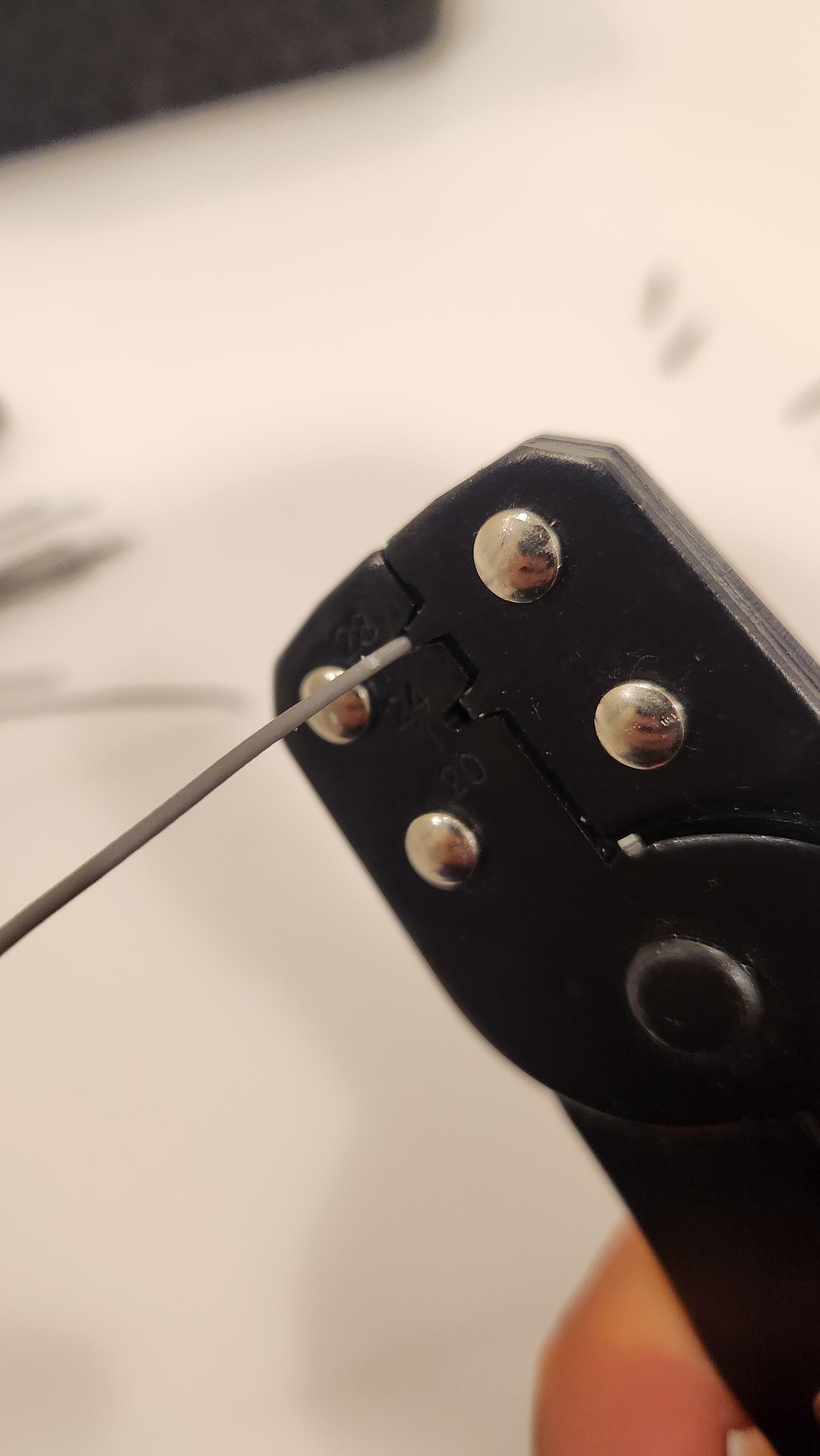
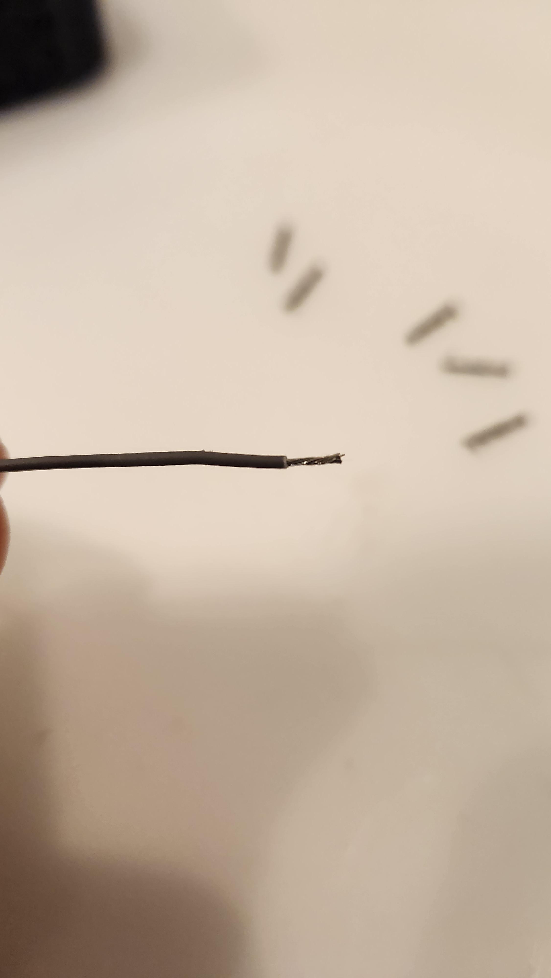


Once you have tuned all the electromagnets (by screwing them further in/out) and identified all the polarities, you now need to solder cables to them. To do this, strip the end of an insulated wire, then wind the enamelled wire around the stripped end. Then apply flux and solder (most solder already has flux in it). Once both wires are soldered, tape them securely to the electromagnet so that the soldered connections are insulated and ensure neither wire is touching the other (I like to tape one cable, then the other, so there is an additional layer of tape between them).
For the negative connections, you will need to make up some plugs with dupoint headers (or similar). Cut 14 thin cables ~90mm long, and then crimp female connections to one end. Then press fit them into a housing. You can then solder the other end of each cable to the respective coil.
Pay close attention to the letters on the PCB as to which coil is soldered where (Bk refers to which electromagnet flips the flap to black and Wt refers to which electromagnet flips the flap to white). A, B, C... refers to which flap you should be soldering to, please refer back to the images below for clarity. You can find the sequence and the layout on the digit break-out board PCB.

For the positive wire of each electromagnet, you simply need to solder them all together and crimp a single female dupoint header to the end. I did this by first soldering a cable to every positive wire of the electromagnets (each pair has a longer and shorter cable). Then the shorter cable of the pair is soldered to the longer one, and the longer one is soldered to the adjacent pair. See the images included in this step for reference.
Make the Digit Joiner PCBs


To make the digit joiner PCBs you first need to use a sharp knife to score both the top and bottom sides just below the dotted line (located on the base of the digit break-out board). Try to score as close to the first terminal as possible, if you score directly on the dotted line, you will have to sand them down later. Then gently break them away by clamping them along the scored line to a hard surface and pushing downwards. Then take four 8-long straight male header pins, and solder them in place (so that the text saying "Black Connector" and "White Connector" faces away from the male header pins).
Solder the Digit PCBs


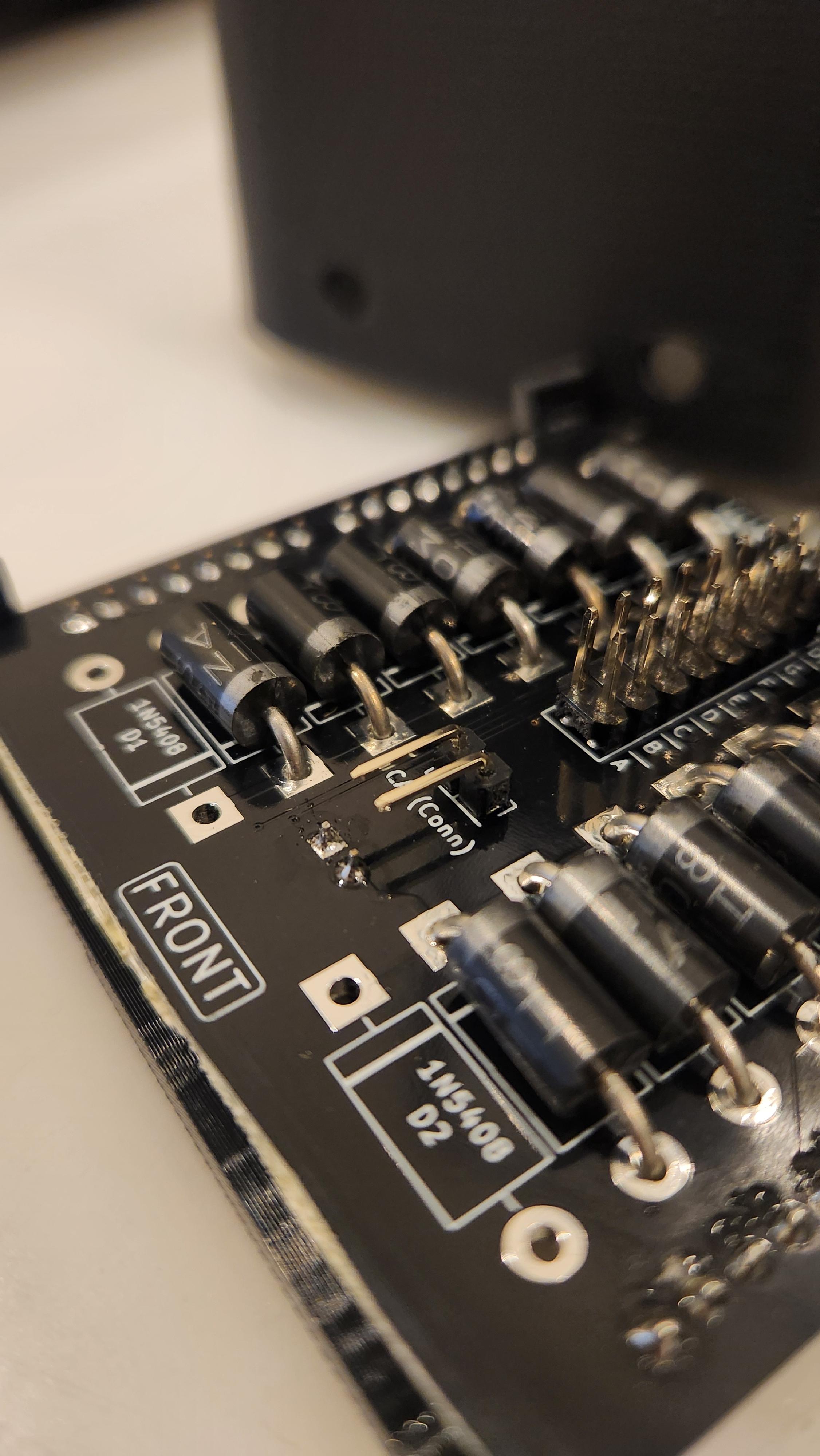


After breaking off the digit joiner PCBs (or leaving them attached if you do not need to use them), we can now proceed to solder the remaining components onto the digit break-out boards. Cut and solder all fourteen 1N5408 diodes into their respective positions (leaving the bottom two empty), paying close attention to polarity (indicated by the white stripe). Then solder all fourteen 1N4004 diodes with the white stripe facing downwards (into the PCB) into the 2x8 connection pads (leaving the top two empty). You can then trim the top side of the diodes so that they are the same length as a standard male header pin. You will see in some images I have soldered a resister and additional wires on the PCB, this was due to a design oversight and the PCBs that you ordered do not have this issue. You will however need to solder a 10K resistor in its respective position (that is not shown on my outdated boards).
Then solder a 1x2 male 90 Deg. header to the common anode (CA) connection as shown (pointing downwards), as well as one 1x2 female header to the common anode input. Depending on the 'type' of digit you are making, will determine if you solder male or female headers to the four 1x8 way rows on the back of the PCB. Female headers should be where a digit is adjacent to another (and will have a smaller slot in the case) and male headers should be where a digit is going to have a cable connected to it (and will have a wider slot in the case).
At this stage, you can check both digit joiners fit by pushing them into the female headers (either the in/out ones - depending on the type of digit you are making). If they don't both sit flush (one overlaps the other) you will need to sand them down until they do. You should wear a mask when sanding fibreglass PCBs to protect your lungs, as well as other PPE such as gloves and eyeglasses. If you find they don't sit flush, try to cut them closer to the solder pads on the next digit (if you are making multiple). This was a design oversight that I will talk about how to improve in the final steps.
Finish the Digit


Now that the PCB has been soldered, and the coils have been wound, it is time to finish the digit assembly! First, take the digit case, and push in both PCB clips into the rectangle slots (such that the one with additional alignment tabs is at the top, and the tabs are facing upwards). These clips should be a tight fit, and if not, you can add some glue (after checking you can clip in the PCB). If you are unable to push the PCB into the clips, you can remove the clips, push them onto the PCB, and then install both clips and PCB into the case at the same time. The PCB will need a bit of extra force to push the female headers through the slots on the back, so be gentle and take your time.
After that, align the centre panel so that the top of the case lines up with the top of the centre panel. You will then need to plug the cathodes and anodes into their respective positions on the PCB (make sure you get the cathodes in the correct order so that A, B, C... and Wt & Bk line up with the markings on the PCB). You can then push the centre panel into the case until it snaps into place. Make sure all the 8 tabs have located themselves into the small rectangular holes on the side of the case. You can then install all 7 flaps, making sure they can rotate freely and are orientated correctly. Then push in both front filler panels, by aligning the middle cut-out to the middle of the digit, and pushing them onto the hexagonal posts of the centre panel. Finally, lock everything in place by installing the front outer trim. Once again, check all flaps can rotate freely. If they cannot, try cutting/sanding a very small amount of both ends of the "nubs" that jut out of them. Even if they could rotate freely before, the front outer trim will pull the posts closer together (locking in the flaps) so you should check all flaps again by hand. If you need to remove a flap, you will first need to remove the front outer trim.
If you are making multiple digits and you want to join them together later, insert the 3 hex joiners before anything else into the side of the two cases. These can be a bit fiddley, and if they don't clip into place, try scaling them down and printing them again.
Optionally you can add feet to the digits by pushing them into the circular holes on the bottom of each digit.

Build More Digits!


Horray! You have built one digit. Trust me, the first is by far the hardest. To test that you haven't made a mistake, take a 12V power supply and connect the positive to the common anode input. Then take the negative and insert it into the female/male headers from top to bottom. It should (in this order) flap A, B, C, D, E, F, G, (and then the bottom one should do nothing) to black, then A, B, C, D, E, F, G, (and again the bottom one should do nothing) to white. Whether you connect the negative cable to the "in" or the "out" female/male headers should make no difference.
Now it is time to build more!!! (Or continue with the next few steps to properly test this digit, and then go back and make more)
Solder the Main PCB


Now it's finally time to solder the main controller. With the use of the schematic and the photos above, you should be able to identify where every part goes. Additionally, the PCB has markings and polarities written on it. For those who are new to electronics, resistors can go in any orientation, ceramic capacitors (small brown disks) can go in any orientation, electrolytic capacitors and diodes have a white line indicating the cathode, and LEDs have a flat edge. For the ICs and IC holders, you will see a small semi-circle on one end, you will also see a small semicircle drawn on the PCB, these must be orientated in the same direction.
For the main ESP8266 chip, first, cut your 15-way female header pins and press them onto the NodeMCU Male pins. Then check what width of pins you need to use (There are extra holes marked "Esp8266 Extra Pins" which can be used if your NodeMCU is wider). Make sure you orientate the chip correctly (with the squiggly PCB antenna facing outwards - as indicated on the PCB).
Upload Code & Add Wifi Credentials

To upload code first download it from my GitHub page. For those who don't know how to use GitHub follow these steps;
- Open the page (by following the link)
- Go to the green button "<> Code"
- Click "Download ZIP"
- Find the file (Flippy-main.zip) in your downloads folder and extract all the files to your desired location
- Then navigate to "Flippy-main\Flippy-main\V8.2_Seven_Segment_Display\main" and open the README
Once you have downloaded the code, follow the instructions in the README text file. It will show you how to download Arduino IDE, all the drivers needed, and how to upload both basic code and the file system. You will need to add the SSID and password of a wifi network for your ESP8266 to connect to, the line number and file are noted in the README.
Solder the Electronics Box


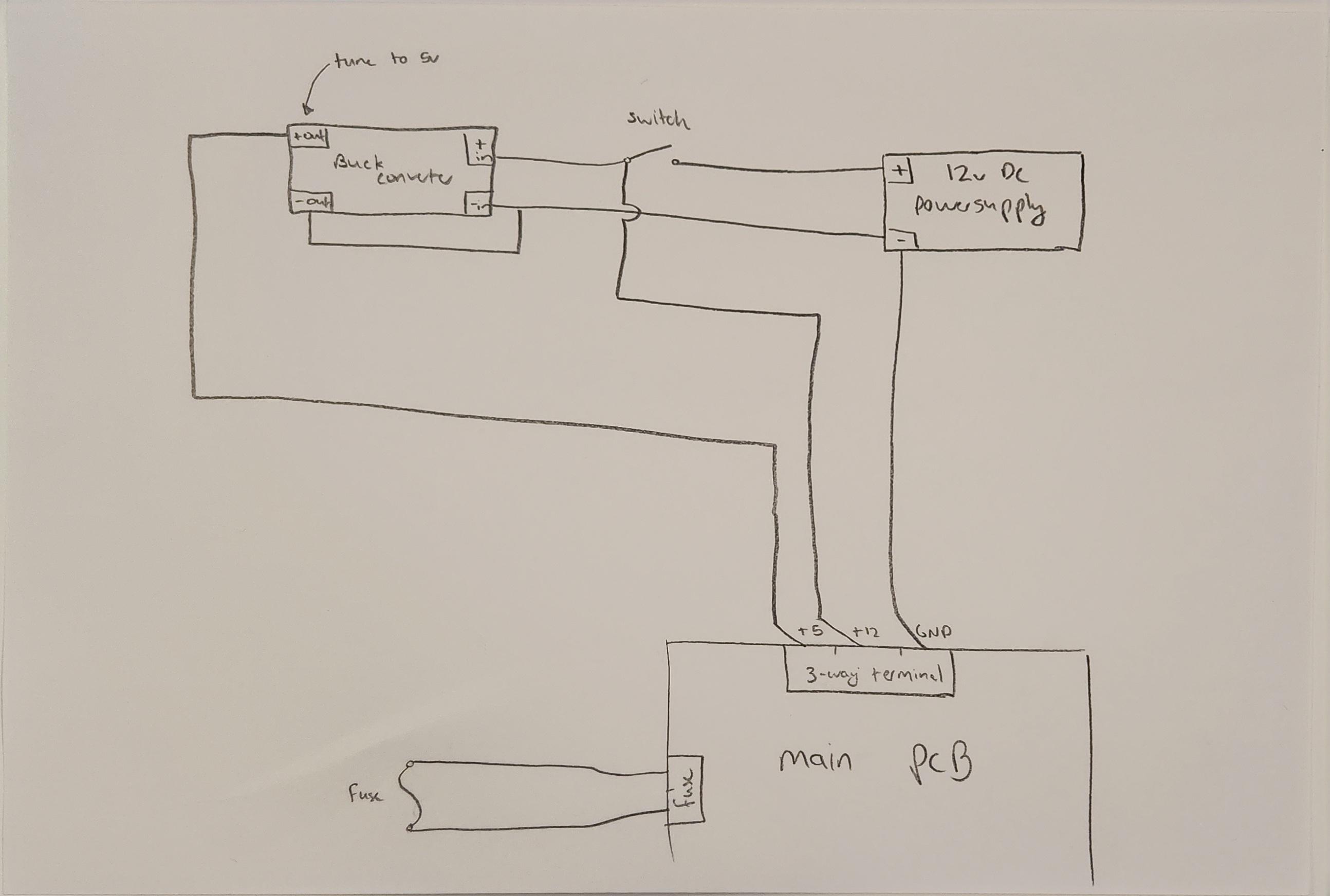
The main PCB requires 5V and 12V DC to be supplied in the screw terminals as written on the PCB. This means you can directly run a 12V cable into the electronics case, through the switch and then into both the PCB and a buck converter. You must use a multimeter and the adjustable trimpot on the buck converter to step down the 12V to 5V which can then be wired into the PCB. Follow the wiring diagram as shown below;

Make sure you push the switch into the front panel before you solder wires to it. To mount both the PCB and buck converter, push them onto the raised tabs as seen in the images above, and then use two small M3 Screws (one for each PCB) to hold them in place. You will also need to solder a fuse to bridge the two solder pads labelled "fuse" on the main PCB, right of the ESP.
There are two rows of "extra pins" which means if you have other projects or functionalities you want to add (for example a speaker, as shown in one of the images) you can easily do so. Similarly, there are solder pads for 3.3V, 5V, 12V and GND, should you need them.

Assemble the Electronics Box


To assemble the electronics box, simply slide the lid into the right-hand side, then use two M3 screws in the top and bottom left-hand corners. If you want to redesign this box to use 4 screws you can, I was trying something new and still need to work on the slide-in design. You can see some other improvements I'd make in one of the final steps.
Connect the Digits and Electronics Box


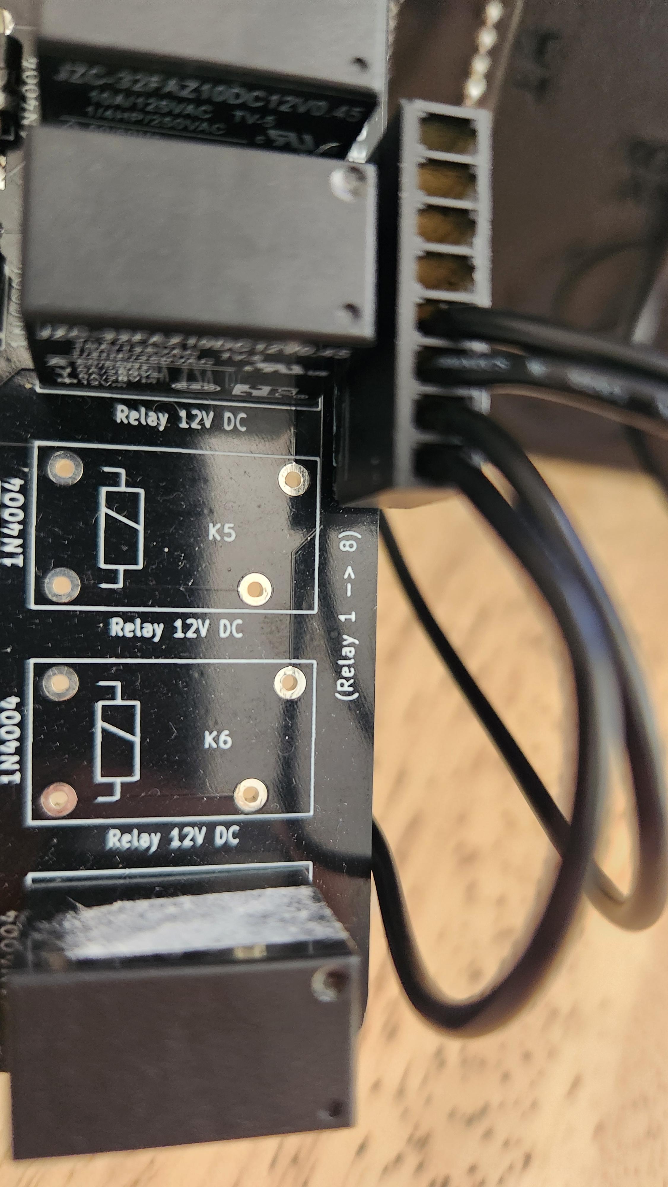
Note: The electronics box has been removed from the images for clarity, you should plug the cables into the box
For this step, you need to pull off the outer two cables of the 10-way IDC so that it becomes an 8-way cable. Then cut two lengths that match the desired distance between your digits and the main controller (leaving a bit extra for the plugs we are about to crimp on). Then strip the ends of both cables and crimp eight 2.54mm female crimps on both ends of both cables. These can then be pressed into four 8-way 2.54mm crimp housings. These can then be plugged into the black and white connectors on the main PCB and then into the first digit. You can optionally spray paint these cables to blend in, I painted mine black.
For the common anodes, you need to crimp a 2.54mm female crimp to the end of your ~21 AWG cable and then a 2-way male 90 Deg. header pin to the other end (see the image below) which is then sealed in heat shrink. You can then plug the male header pins into the back of each digit in the common anode socket, and then push the crimps into an 8-way 2.54mm crimp housing. This housing is then plugged into the relay header pins on the main PCB. Take special note of the order written for digits 1-8 as indicated with the arrow on the PCB. The digits are numbered 1 to 8 from right to left (rightmost being 1 - see step 1 for some example layouts). You can then also make any additional cables needed to join digits that are separated by a gap in the same way, and then join the remainder of the digits by inserting the joiner PCBs into the backs of them.


PLEASE NOTE:
For some reason, the first time you turn on the counter you may hear the relays click, then the blue light on the ESP dim as it continues this cycle. If this happens, unplug the relay plug, power the ESP on, wait 5 seconds, and then plug the relays back in. This will prevent the cycle and boot up the ESP. I have no idea why it does this, and if you have any ideas, please leave a comment.
Done!!!


Congratulations! The hard work is now done... phew! The next few steps will walk you through using the web interface and show some provided example modes!
The Configuration Menu
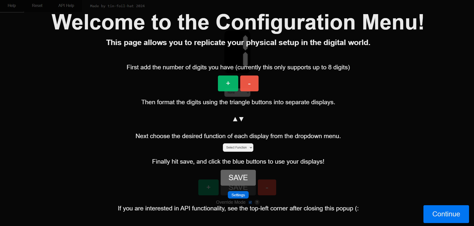
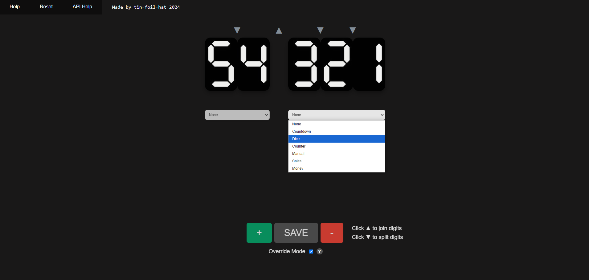


The configuration menu is at the heart of this design. Once the counter is switched on, make sure you are connected to the same network as the counter and go to http://flippy.local, make sure you enable JavaScript and allow the insecure connection. For those who don't understand why it is an insecure connection, it is because your ESP hasn't provided an SSL certificate (hence HTTP not HTTPS) to the web browser, but this isn't an issue in our case as you own the server so know it isn't malicious. Regardless, it is best practice not to enter passwords, bank details or sensitive information.
This will open up the config menu and will welcome you with some instructions on how to use it. From here you can add digits, create groups of digits (displays) and assign modes to them via a dropdown. Some modes need a certain number of digits and thus will not be available for all displays. You can also turn on or off override mode which changes the way the display updates. It will remember all your changes and prompt you if you forget to save them, and will load them back up when you re-open the page. You can also choose to completely reset the settings back to the defaults if you mess something up. Once you save your displays, you are able to click the blue "settings" button and you will be redirected to the mode of your choosing.
If this page, or any page fails to load properly, reload the page until it works. Due to the ESP8266 having a slow upload speed, and modern browsers expecting super fast server responses, sometimes your browser will interrupt and cause an error. Reloading a few times will fix this.
Basic Input Mode (Manual Mode)

As the mode implies, this is simply an input menu where you can choose what you wish to display. You can choose the alignment, left, right or centred. You can also choose the type of input, text or numbers (to be safe, just leave it on "text" as setting it to "number" doesn't do anything special in this case, and text will work for a combination of letters and numbers). After typing in your phrase or number, simply hit enter and listen to the clicks!
If you input a number or word that is too long, depending on your alignment, it will truncate (cut off) the extra letters/digits. Some letters are impossible to display with a 7-segment display such as "m", these will be replaced with a blank digit. Similarly, in some cases, only the lower case or upper case is possible, such as the letter "A". The counter will give preference to your inputted case where possible (for letters where both are possible such as "o" and "O").
Special characters will become blank digits, apart from hyphens "-" which will allow you to display hyphenated words and negative numbers.
Countdown Mode

Countdown mode allows you to pick a date and time. This lets you have a display show you just how long until your favourite day of the year arrives! Given it is the festive season (as I am writing this) maybe you could count down until Christmas or New Year's Eve! First, it will display the number of days "XXd" then the number of hours "XXh" and finally the minutes "XX" until you reach 0, at which a quick animation will play and then it will remain at 0. You can start and pause this countdown as you desire. Don't forget to choose the correct timezone too!
Dice Mode (Random Number Generator)

Dice mode (as the name suggests) turns your counter into a game of chance! By first selecting the number of faces of your dice (most commonly that would be 6), and then choosing the alignment (out of left, right, and centre), you are ready to roll. Hit the large green button and watch a "rolling" animation play before the final result is shown. You can also optionally choose to have the number displayed to the screen (incase your counter is a bit faulty).
Clock Mode
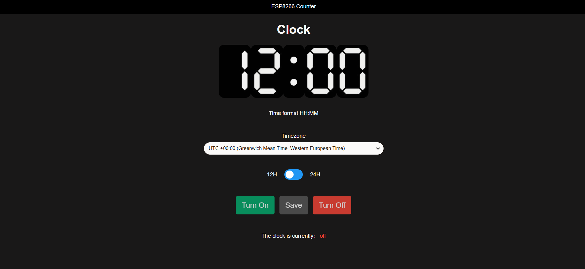

I imagine this will be one of the more popular modes I have coded. You can download and print a colon which can be inserted between digits to make your counter look more like a clock. Depending on if you have 4 or 5 digits will determine which of the two screens above you are shown. With 4 digits you can choose between a 12 or 24-hour clock, whereas with 5 digits you are forced to use a 12-hour clock, but will have the letter A or P shown (which represents am or pm). You also have the ability to choose any timezone, as well as stop or start the clock as you desire.
Counter Mode

Counter mode is the final mode I have coded and left available for you. This mode will give you a set of buttons (more digits equals more buttons) which will allow you to add or subtract a set amount. This lets you keep track of whatever you want, in an easy and fun way. You can also add or subtract custom amounts via the input field! It will allow you to display numbers up to 99 (if you have 2 digits) or 999 (if you have 3 digits) and so on. It will also allow you to display negative numbers (if you have more than one digit) down to -9 (if you have 2 digits) or -99 (if you have 3 digits) and so on.
Using This Display in Other Projects, APIs and Adding Modes (Advanced)

This step is intended for more advanced use of this project and can be skipped if you only wish to use the pre-programmed modes.
The goal of this project was to make it highly modular. This counter can easily be added to other projects, either as a completely separate wireless component or as a fully incorporated section. The code is object orientated with each counter being a separate object. If you wish to use the ESP8266 as the main controller for a completely different task, you can edit main.ino and add your own code at the end of the start-up. Additionally, there is only one line in "void loop" which is wifiChecks(), simply call this as often as possible in your personalised loop. You can directly create Counter objects and call predefined functions such as "displayNumber", "displayWord" or "clearDisplay". I have tried to comment as best as possible if you wish to further edit the code.
Once you have uploaded my code, you can open the API Help menu on the configuration menu which will show you the API endpoints you can call, and what JSON to pass in (also included as an image above). This allows you to keep your project separate (with another ESP) that can then wirelessly call this API as you desire.
If you want to add your own modes, simply edit the function getModesJson in modes.cpp to add another menu option;
The first array parsed in should contain {modeName, constraint logic (AND/OR), number of constraints} and the second 2D array should contain all the constraints {{logic (>/</=), number} ...}. The constraints determine how many digits are needed before the mode is allowed. For example, a clock needs 4 or 5 digits (HH:MM or HH:MM A/P for am/pm), this means the constraint logic should be OR and the two constraints are = 4 and = 5. Similarly, if you wanted a mode to have between 3 and 6 digits the constraint logic should be AND and the two constraints would be > 2 and < 7. You can see an example below:
Then add an additional HTML file in the "data" folder, which should be called {modeName}.html (without the {}), you can then obviously add JavaScript and CSS files to style the page as you wish, and in your JavaScript, you can call the API endpoint as described on the main config menu. You will also notice that you have 1 URL parameter which includes information you will need when calling the API, this is base64 encoded and simply needs to be decoded (if you include modes.js as a module you can access some helpful basic functions).
Adding More Than 8 Digits (Highly Advanced)

If you choose you want more than 8 digits you can build an expansion board. The shift register pins are available on the main controller and with a multimeter you can find which pins they correspond to (or use the schematic). You will then need to add an additional shift register and Darlington transistor array for every 8 additional digits you want. You will also need to add a relay for each digit (connected to the Darlington transistor array) as well as supporting components (diodes etc. - please refer back to the schematic). There are also spare 3.3V, GND, 5V and VDC (12V) pads which you will need. The code is also designed for 8 digits so you will need to re-program the configuration menu page, as well as some code in counter.cpp and possibly wifi.cpp, this is an extremely advanced thing to do compared to just building this project and should only be attempted if you know how to design PCBs and how to code in C++, HTML, CSS and JavaScript.
I don't expect anyone to do this as building more than 8 digits would be very tedious :)
But it is possible should you choose you want to attempt it.
Adding a Decimal Point (Highly Adcanced)

This design doesn't include any decimal points or colons, however, if you want to take on that challenge of adding those yourself you can. The digit breakout boards have room for diodes for a decimal point (Dp) and they are already wired into the main controller. However, you will need to modify the code to add decimal point functionality, as well as add a physical decimal point in CAD.
Pros and Cons of These Digits


So why is this digit any good??
Pros:
- They have a really nice mechanical sound
- They don't use continuous power once something has been displayed
- You retain the full functionality of a 7-segment display, allowing you to display any letters, numbers or animations you'd otherwise be able to display
- You can chain large amounts of digits together
- They are much cheaper than other mechanical commercial displays (~$9 AUD per digit) - at the cost of more tedious work
- And they are very achievable for a slightly advanced DIYer to build
Cons:
- Far more expensive than LEDs
- Very time-consuming to build
- They are affected by other magnetic sources
- They are somewhat fragile (And thus not suitable for high-impact environments)
- Isn't very scalable (to a very large or very small display)
- And compared to LEDs, you need a huge amount of extra components to control them (but no more than similar commercial mechanical 7-seg displays)
It is important to note that part of this project involves the controller circuit. This could be adapted to suit other commercial mechanical 7-segment displays. The main controller is the most expensive and technical part of the project, and you would still need to build an equivalent if you bought a commercial mechanical display.
EDIT: As I was making this project, Engineezy released his design of a "rack-driven mechanical 7-segment display". If the electronics of this project scare you, then you can check out his design on YouTube (you do have to pay for it). He has done an amazing job and for those not sure which one to build, here are some quick pros and cons when compared to his:
Pros:
- His can only display numbers 0-9, whereas mine can display any character normally possible on a 7-segment display
- Due to the camshaft design, you must display every number from 0-9 when changing from displaying a 0 to displaying a 9, whereas mine can go directly from one number to another
- I have preprogrammed modes you can use, although I do believe he may have a dice mode available (as shown in a YouTube short)
- Mine has free downloadable files & code
Cons:
- More complicated to code and connect electronically (Although I have done that for you)
- Mine is much more tedious to build due to additional wiring and winding of electromagnets
- Mine has an initially higher cost due to needing a separate controller PCB (that at first glance appears more complex, and thus expensive than his controller PCB)
Improvements


This project still has room for improvement! Below I have listed some of them that you may choose to tackle;
CAD Improvements
- Increase the space between digits so that the magnets don't interfere with each other (Note this will require a design change to the PCB joiners)
- Consider a more efficient way to make the electromagnets
- Add a chassis mount for the fuse
- Design a better way to clip digits together
- Add a lip to the electronics box so that the lid doesn't sag inwards
- Fix the positioning of the flash and reset button cutouts so they actually line up with the NodeMCU in the electronics box panel
PCB Improvements
- Flip the direction of the NodeMCU (so the USB is more accessible)
- Fix the footprint of the NodeMCU as it turned out to be too narrow
- Change the tab system of the PCB joiners so rather than 2 separate joiners, there is just one. Hence, decreasing the distance between the black and white in & out sockets and headers so you can use one long female header strip rather than two shorter ones
I invite you to remix and personalise this project and share it in the "makes" section on Instructables. If you do share or remix this project, please credit me and this original design (as per the licence). This model is not intended for commercial use (aka the files must be free) so that hobbyists can continue to enjoy making! However, if you are interested in making these to sell to others, please be in touch with me.
Version 2!!

Version 2 is now released! The difference is the cases are slightly more reinforced, the breakout PCBs (V2.5) are fixed up and V-cuts have been added, and most noticeably the magnets are now hidden within the flaps.
You can find the modified parts on MakerWorld
Not only that but there are some paint trays designed to help you quickly paint the magnets to suit the V1 design should you wish to hide the magnets. You can see some examples of that within the V2 video on YouTube. I find that the painted V1 digits are the most reliable version (as the flaps are lighter) and they make a sharper click sound (rather than a duller noise from V2 due to plastic-on-plastic collisions).
Final Comments


Hopefully, if you've made it this far you've got a super cool mechanical 7-segment display! Thank you so much for reading this instructable and watching the YouTube video, I hope you found it entertaining and interesting. If you have any queries don't hesitate to drop them in the comments! Best of luck!!