3D Printed Home Server – 6 Bay ZimaBoard NAS
by salimbenbouz in Circuits > Computers
36236 Views, 251 Favorites, 0 Comments
3D Printed Home Server – 6 Bay ZimaBoard NAS


I was juggling too many small SSDs for backups, so I set out to build something more permanent. In this project, I walk you through the build and assembly of this custom NAS enclosure powered by the ZimaBoard.
Supplies


Parts
- 1 x ZimaBoard 832 Single Board Server Amazon
- 2 x Noctua NF-A4x10 FLX 3-Pin 12V (40x10mm) Amazon
- 2 x Noctua NF-R8 redux-1800 3-Pin 12V (80mm) Amazon
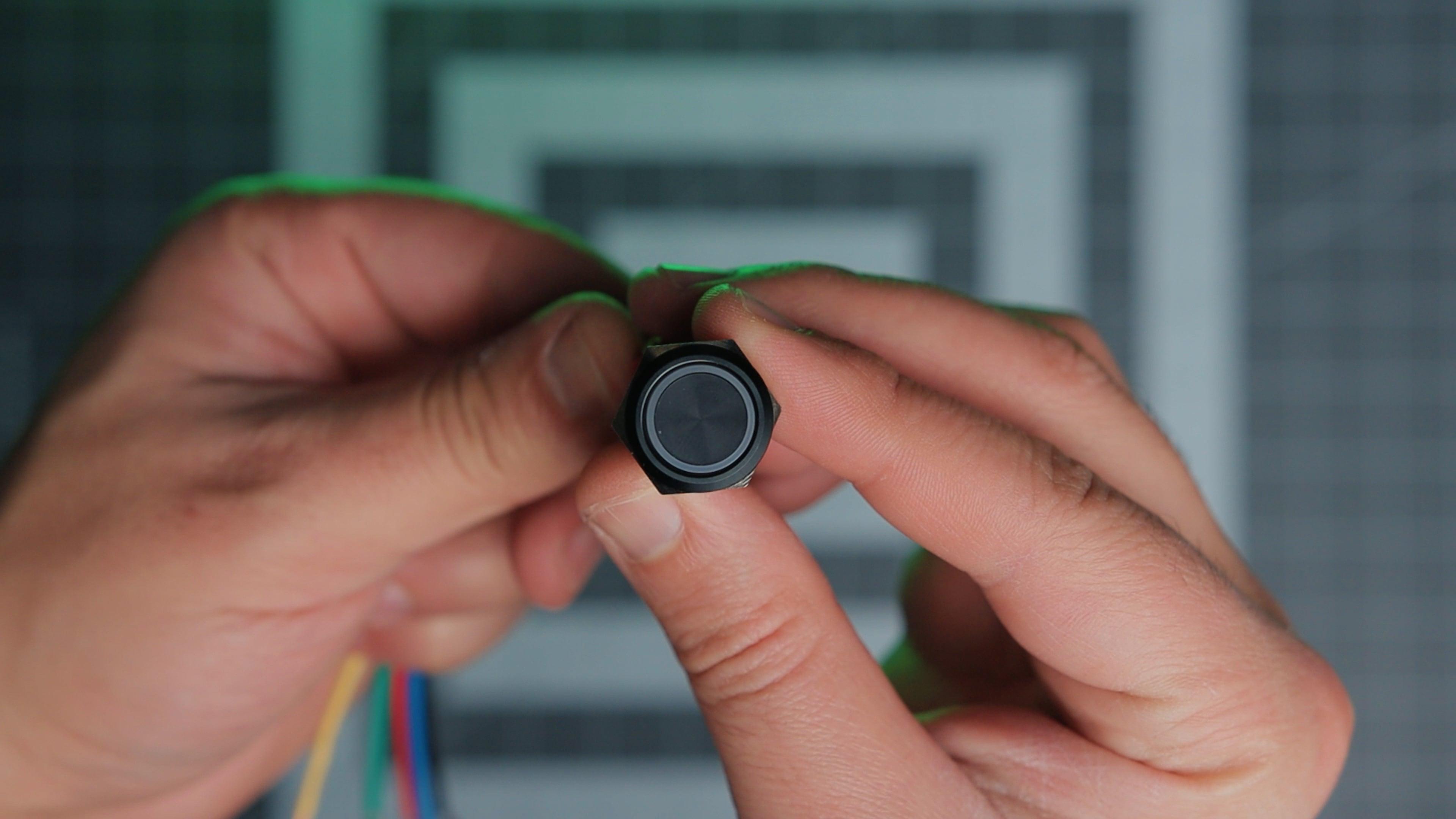
- 1 x Momentary Black Push Button 12V LED Ring Head (16mm hole) Amazon
- 1 x SATA PCIE Expansion Card (4 Ports) Amazon
- 1 x 90 Degree PCI Extension Cable (15cm) Amazon
- 2 x Molex IDE Male to 3 x 15 Pin SATA Power Supply Amazon
- 1 x Power Socket Inlet Module Amazon
- 6 x SATA 22 Pin (7+15) Male to 22 pin Female Extender Amazon
- 1 x Multiple Output 5V(10A) 12V(12A) Power Supply
Fasteners
- 52 x M3 x 10mm-12mm Hexagon Socket Countersunk Head Screw Amazon
- 20 x M3 x 10mm Hexagon Socket Head Cap Screw Amazon
- 72 x M3 Heat Set Inserts Amazon
- 12 x M6 Hex Nuts Amazon
- 29 x M6 Nylon Washers (1.2 mm Thickness) Amazon
- 6 x M6 Fully Threaded Rods Amazon
Power Adapter PCB
Tools
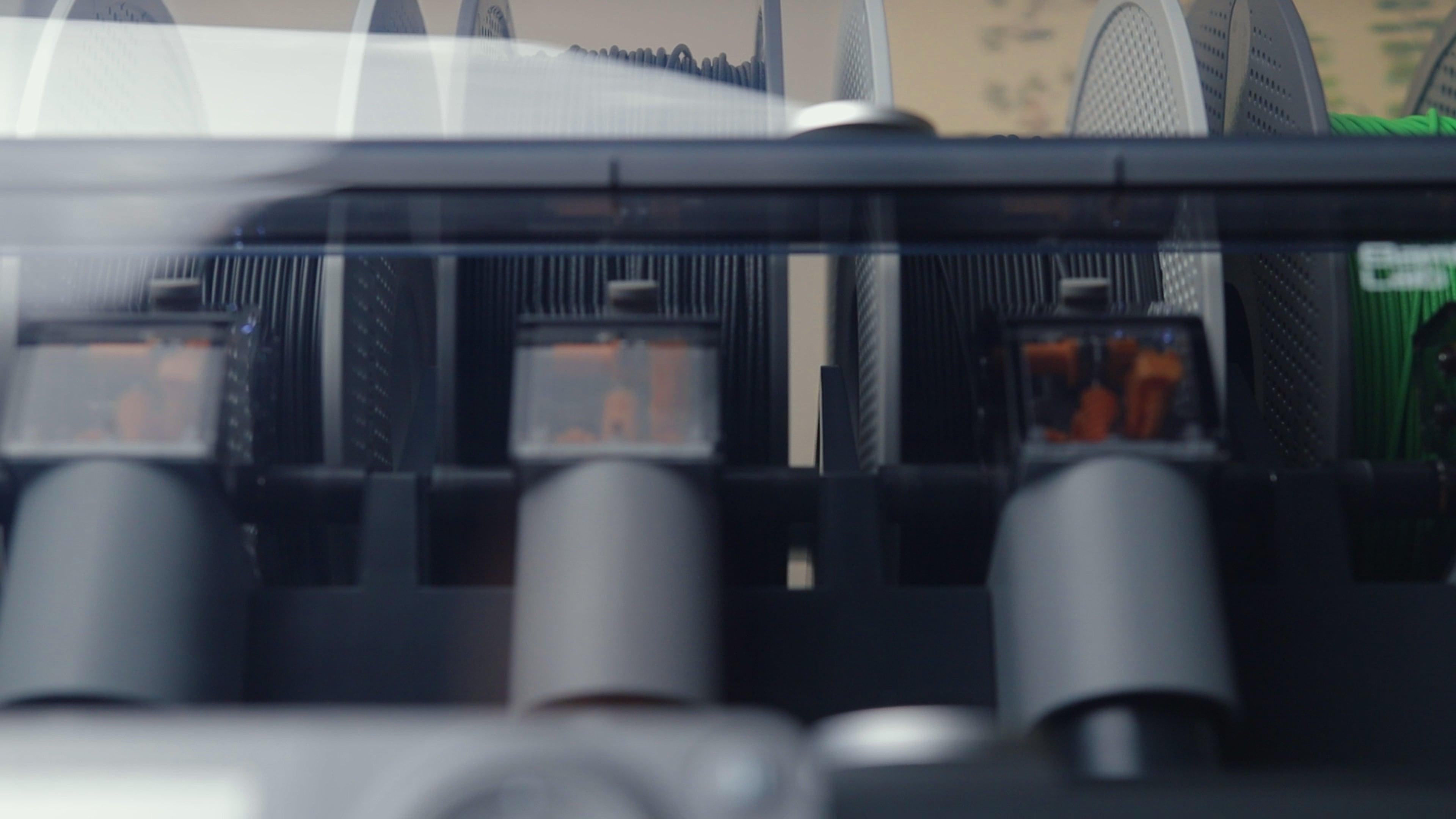
- FDM 3D Printer Bambu Lab P1S
- Filaments (ABS GF, PETG HF) Bambu Filament
- Precision Screwdriver Set Amazon
- Soldering Station/Iron. Amazon
- Helping hands Amazon
- Wire stripper Amazon
- Wire Connectors Amazon
- Wire Crimpers
- Wires (14 AWG, Dupont wires)
- Heat Shrink
- Flux, Solder
- Flush cutters
- Tweezers, pliers
Affiliate links may be included. I may receive a small commission at no additional cost to you.
Watch the Build Video

In the project video, I walk you through the entire process of designing and building this enclosure. Watching it will provide an understanding of each step and how all the components fit together.
3D Printing


The enclosure files are available in different formats in the GitHub repository. You can grab them from there or export the format you prefer using the Fusion Embed below.
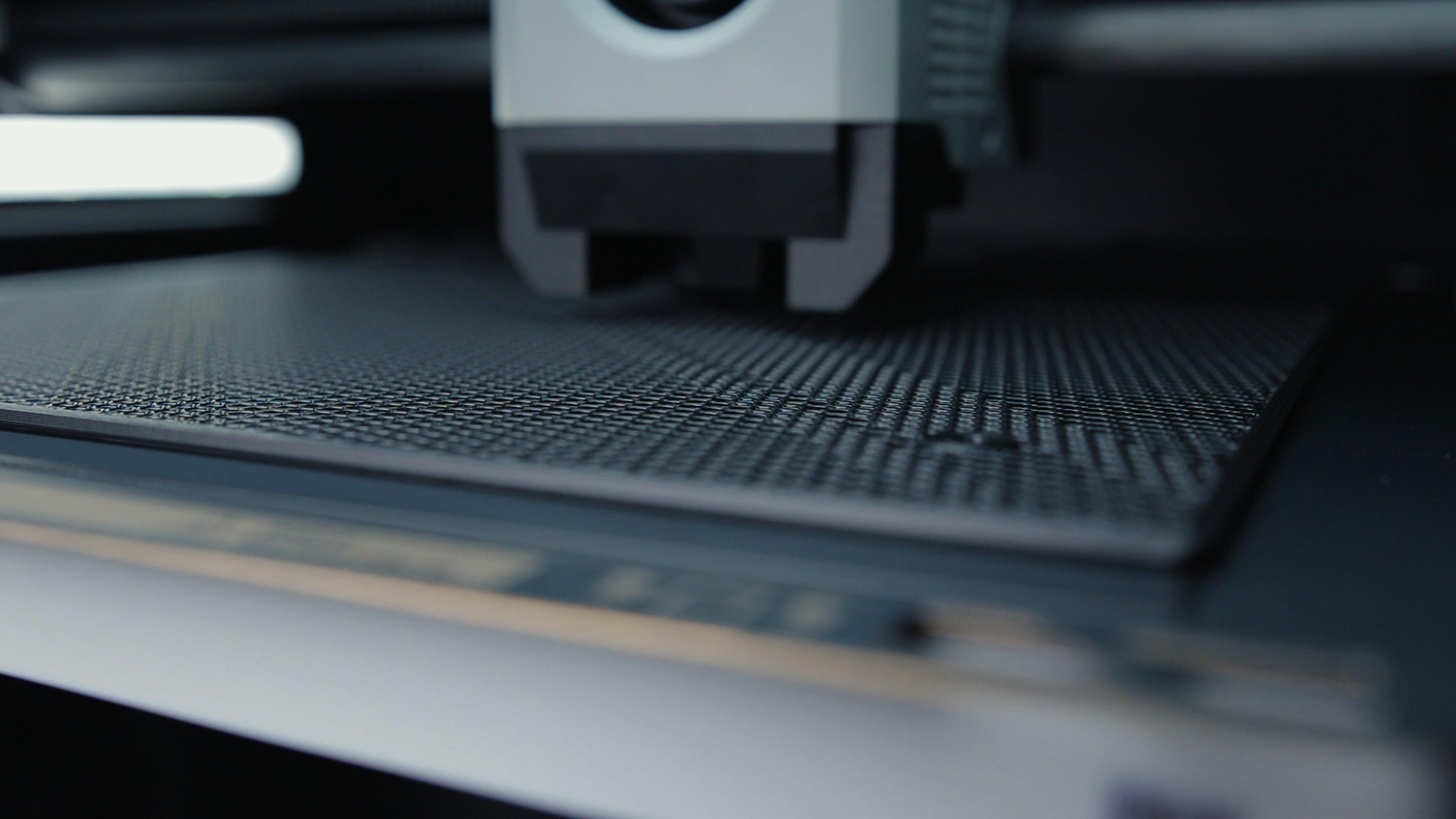
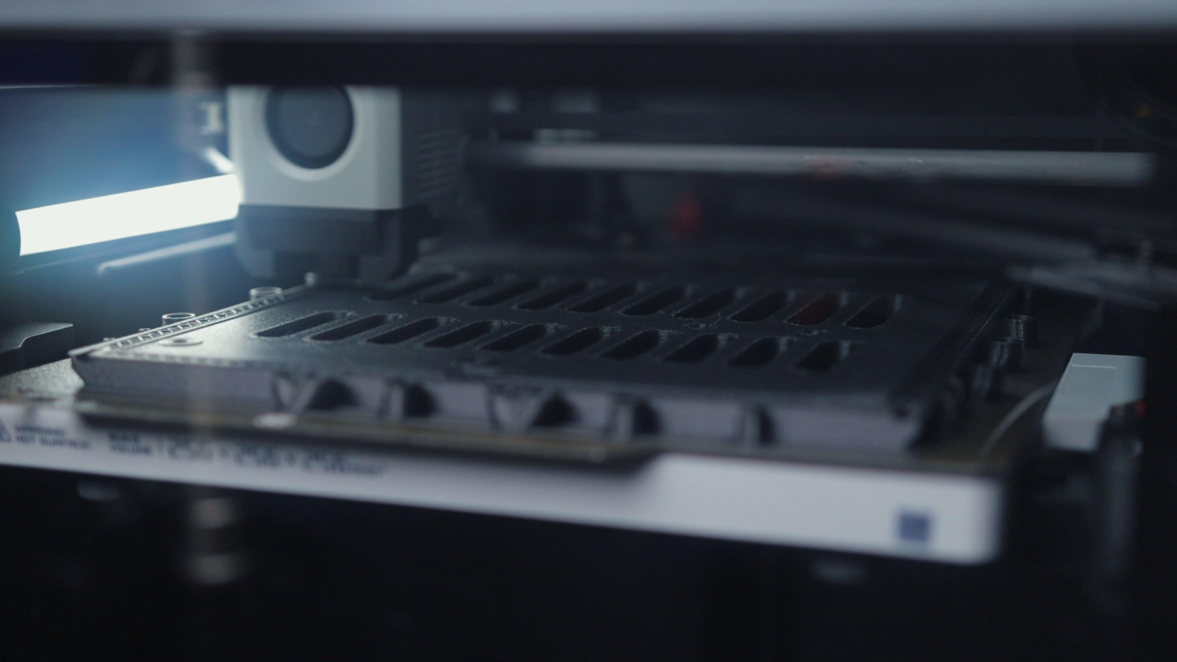
All the internal parts are printed in ABS-GF since it has better thermal performance. The drive caddy and the separator in the drive cage are also printed without top and bottom layers, using a honeycomb infill pattern to help with airflow while keeping the parts strong. I used the same approach for the outer mesh panels, which I printed in PETG HF with higher infill density for a cleaner look. You can tweak this based on your needs by adjusting the infill settings in your slicer. Just keep in mind that the more density you go with, the longer the print times will be.
I batched similar parts together and ran several plates one after the other. ABS tends to lift from the print bed, so I added a 5mm brim to all the flat-printed parts to help with that.
Post-processing


After everything was printed, I started the cleanup by removing all the brims from the ABS parts and going over the edges with a deburring tool to clean up any leftover material. The only part that needed a few tree supports was the Base, but even those came off pretty easily.
If you want to adapt this design to fit something other than the ZimaBoard, this is the part you’ll want to modify, along with the back IO plate.
Once the cleanup was done, I installed the 72 x M3 heated inserts into all the mounting points.
Electronics


The first thing here is modding the ZimaBoard by installing the two headers. Like I mentioned in the video, I ran into problems with the pads since they were already flooded with solder. I highly recommend taking the time to clean them up properly and make sure they’re clear before soldering the headers.
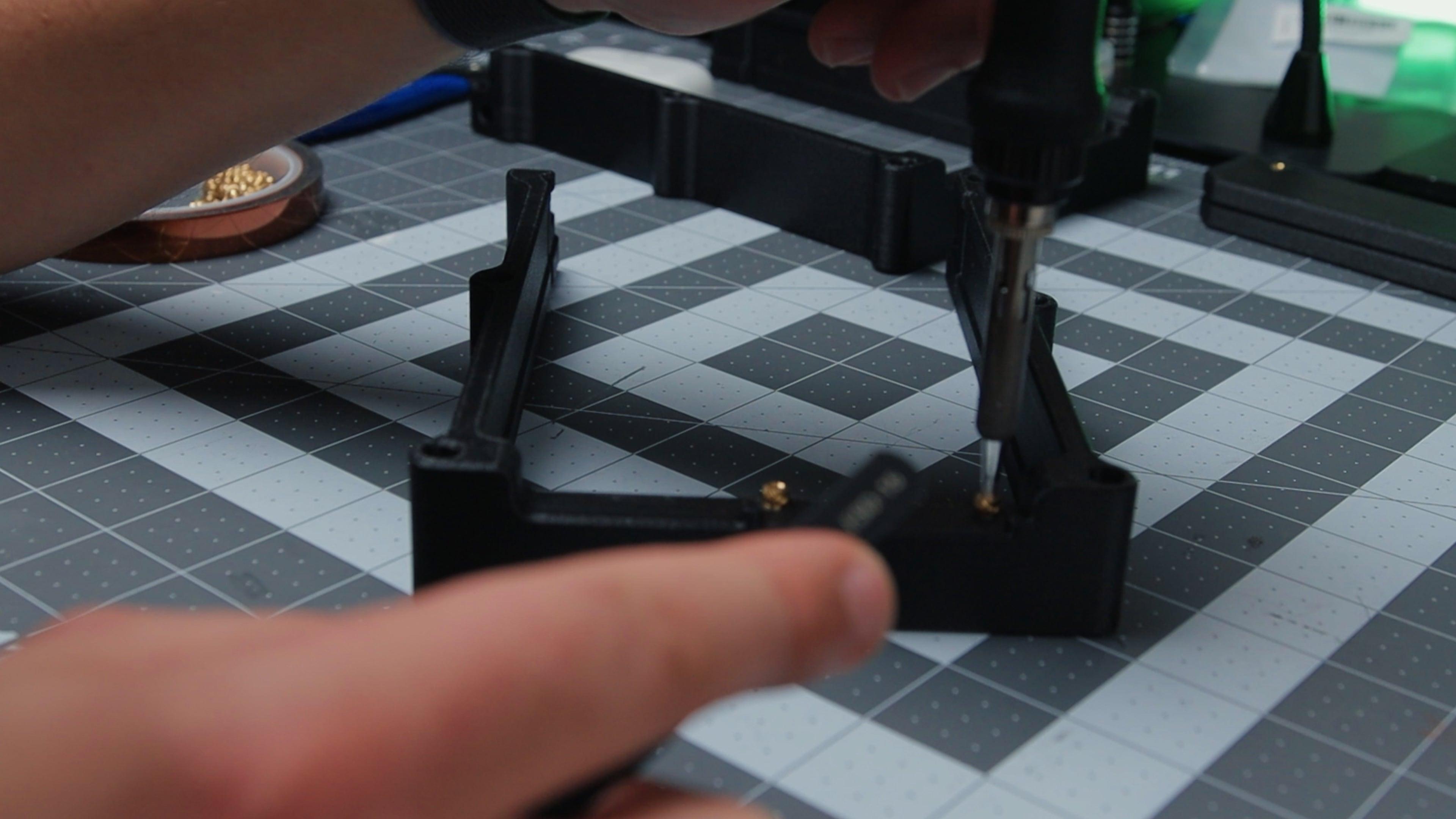
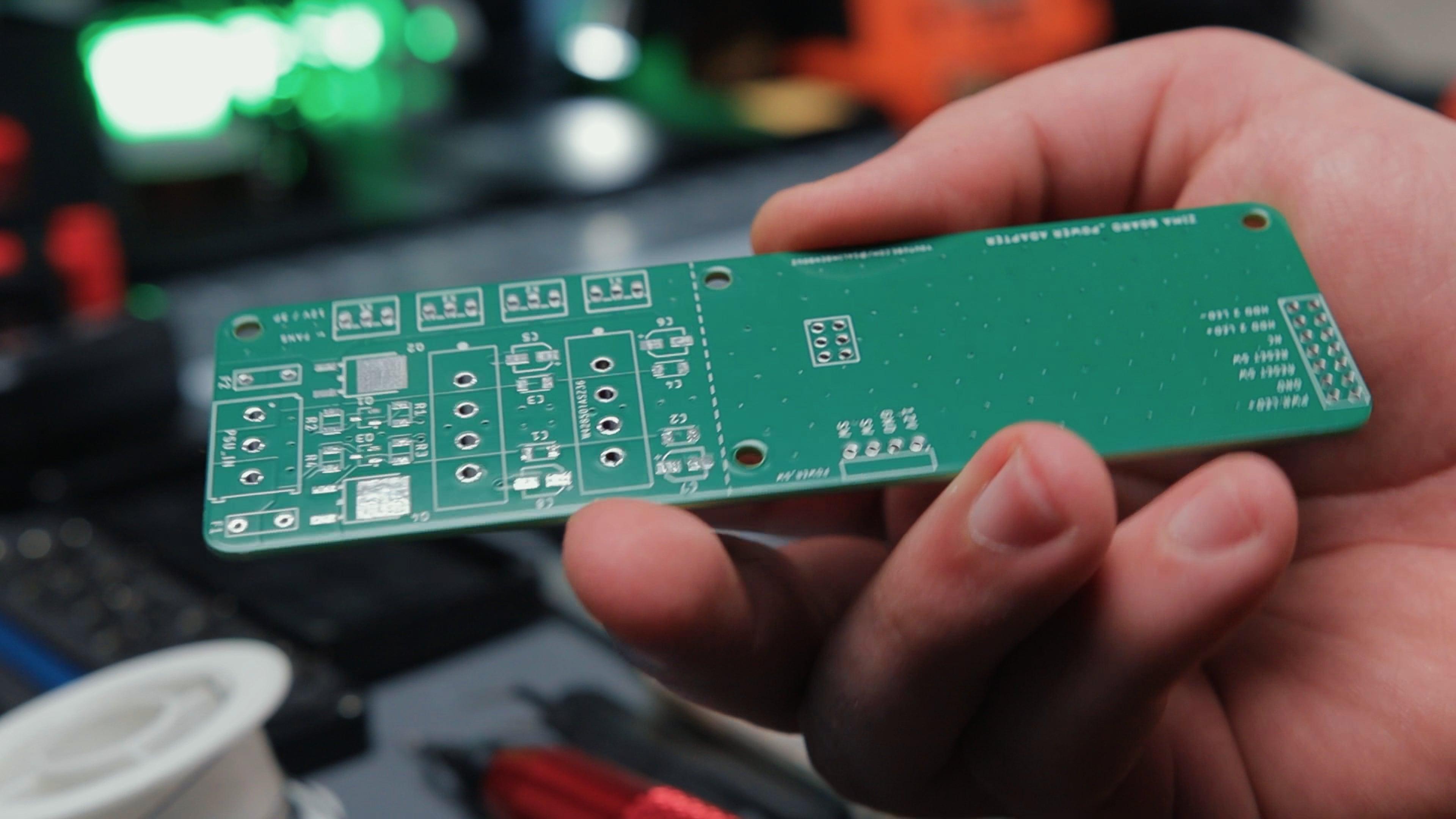
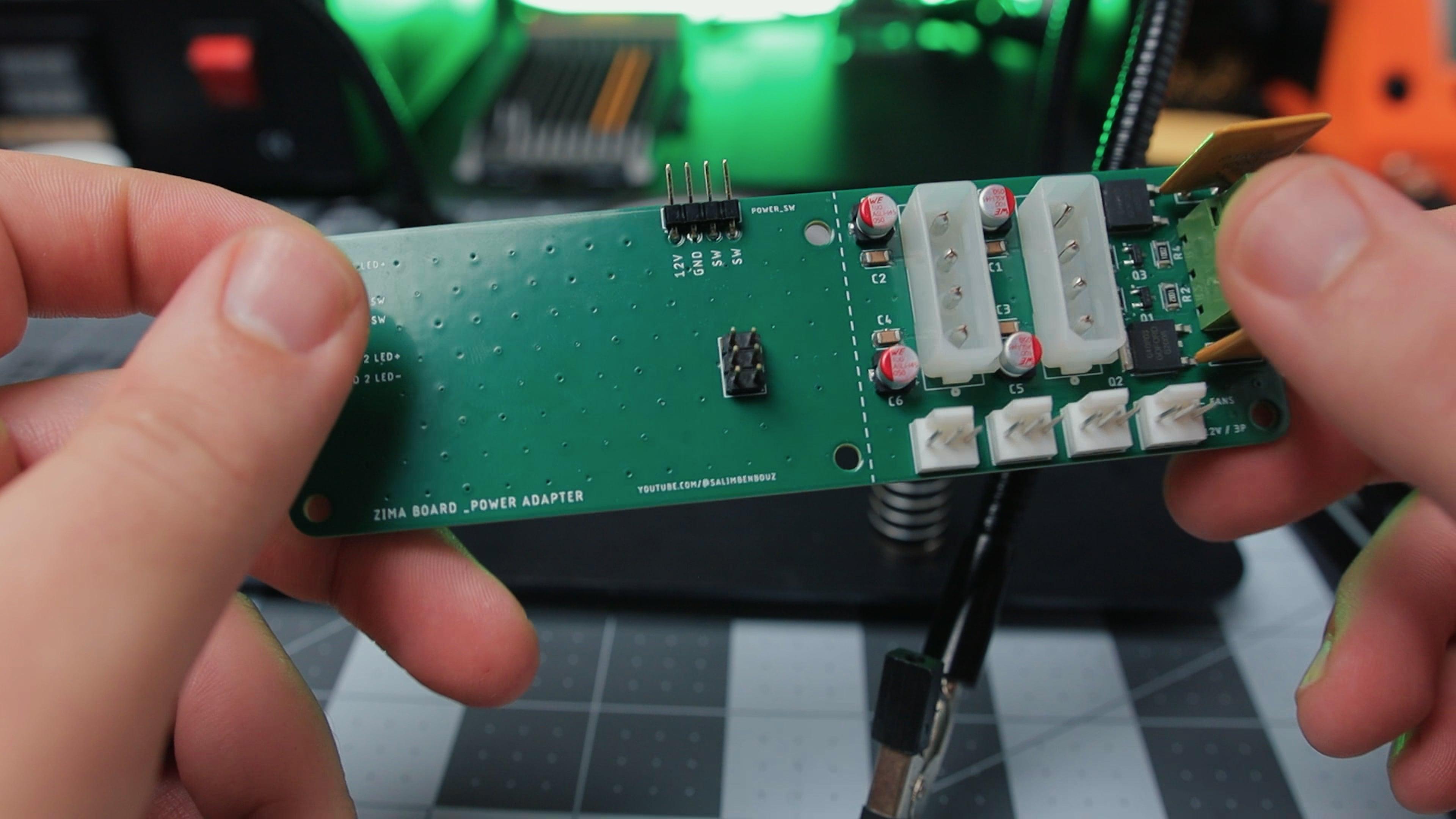
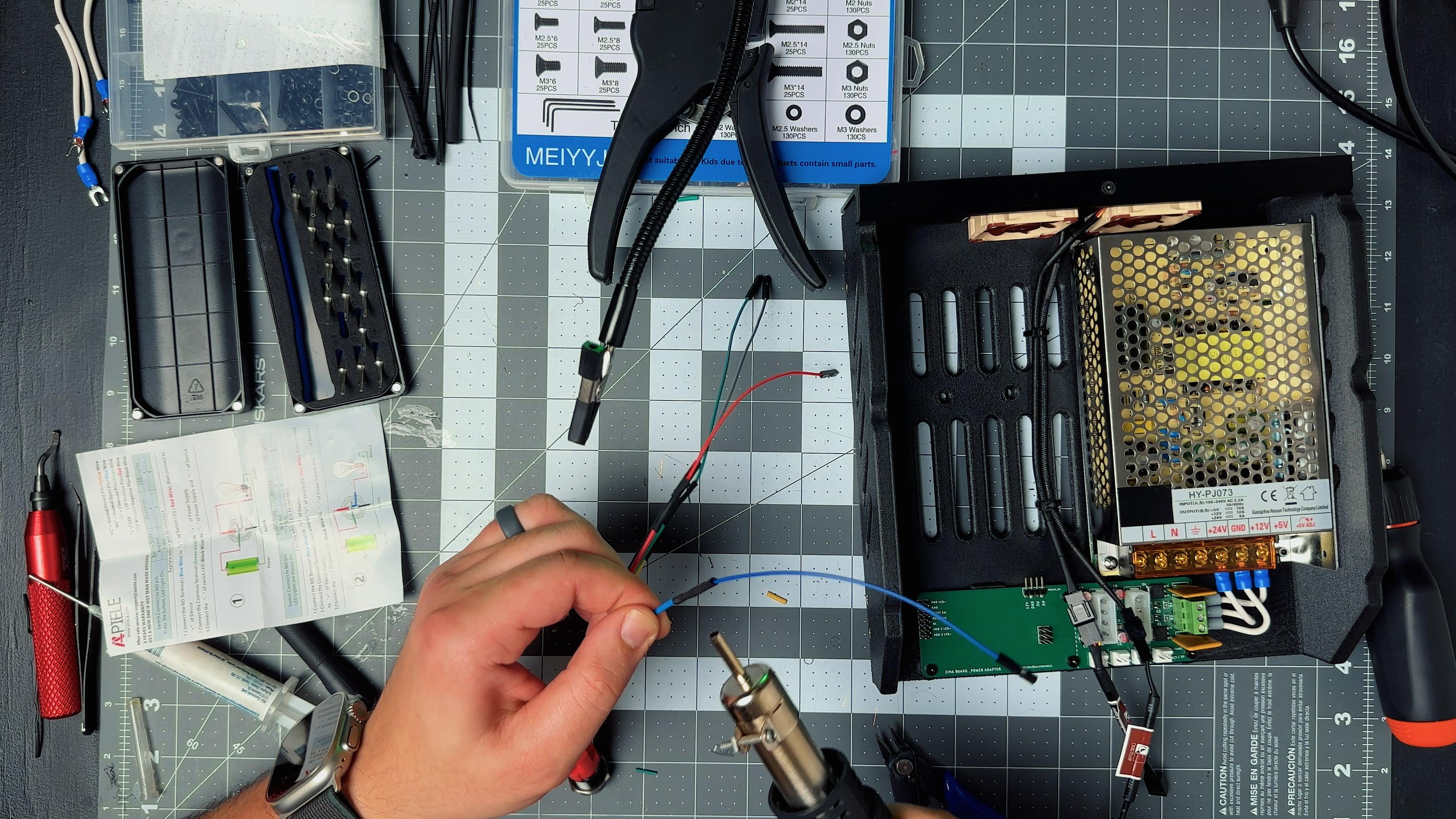
Next is the adapter PCB, which you can get from PCBWay. The Gerber files are available in the GitHub repo. This board handles power distribution to the drives and cooling fans, adds power control based on the ZimaBoard's state, and includes a header for the main power button.
I started by soldering the SMD components using a hot plate, but they’re easy enough to do by hand. After that, I added the through-hole headers, Molex connectors (these need a jumper cable to connect to the power splitters), fuses, and terminal block for the power supply.
⚠️ Disclaimer:
The power supply I used ended up being way below spec, even though the label said otherwise. I had to replace it twice while testing and plan to change it completely, which is why I didn’t provide a link. I recommend going with a reputable brand like MeanWell for your project.
Also, mains power is no joke and can seriously hurt you. Make sure everything is unplugged when wiring the receptacles and connecting the power adapter PCB to the rest of the circuit. Please take proper precautions.
Assembly


The Base
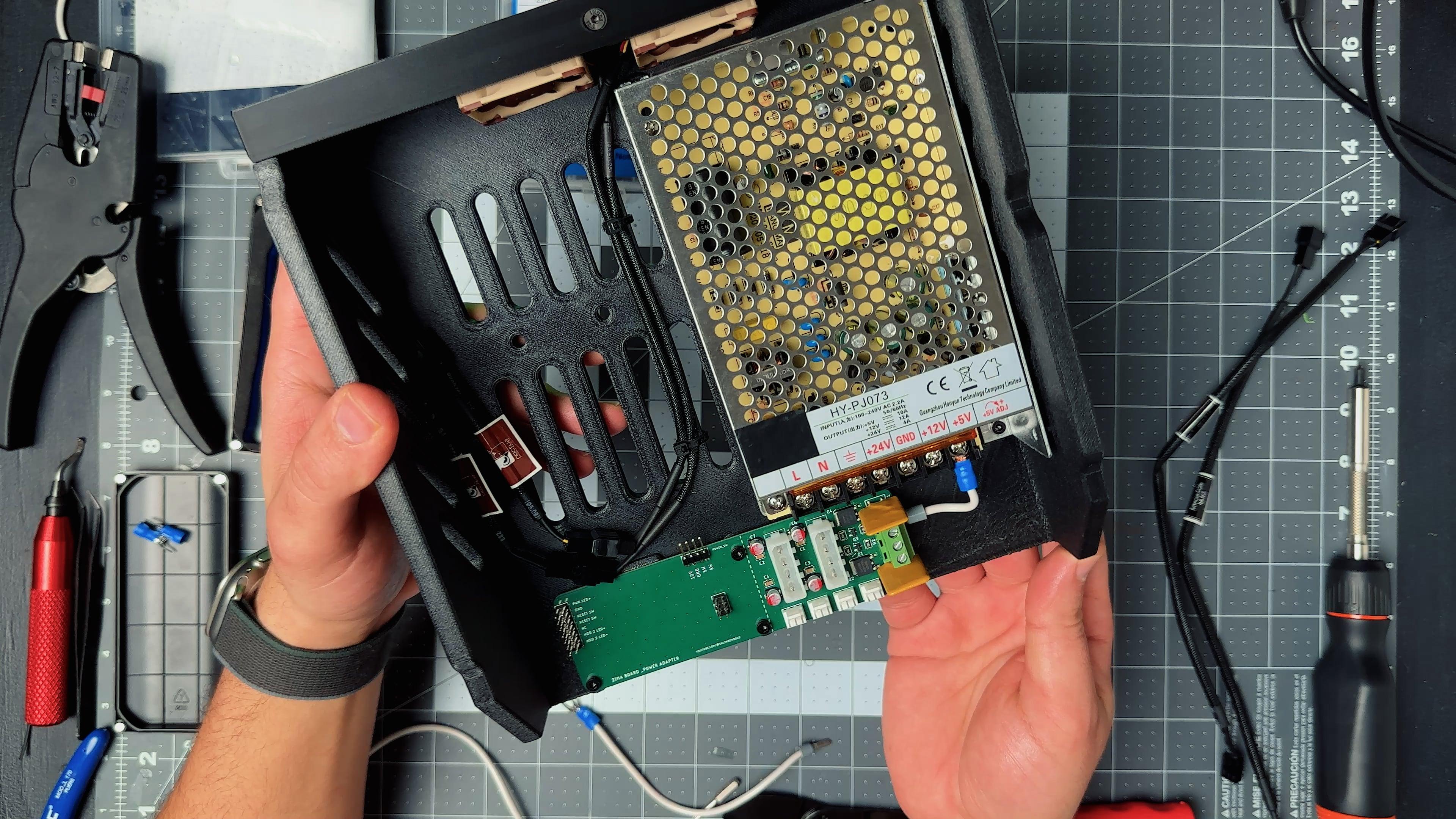
To start the assembly, install the two small exhaust fans and secure them to the base using the provided screws. Then mount the power adapter PCB and the power supply using M3 socket head cap screws.
Once those are in place, run the short power cables from the PSU to the adapter board using thick 14 AWG wire, crimped with proper connectors on both ends. I also terminated three wires for the 110V AC receptacle and screwed them into the PSU.
The illuminated power button needs to be extended using Dupont wires so it can reach and plug into the right-angle header on the adapter PCB.
As mentioned in the video and the previous step, the two Molex connectors also need jumper cables to connect to the power splitters for the drives. I found the correct sleeves and connectors on DigiKey, and they’re listed in the BOM.
⚠️ Please pay close attention to wire colors and connector orientation. It’s easy to flip them by accident and feed the 12V into 5V rail.
The ZimaBoard plugs into the adapter PCB using the two headers installed earlier. There's a small 3D printed support piece that goes near the SATA connectors to help keep the Zimaboard upright and stable.
Next, plug in the 90-degree riser cable, install the PCIe SATA expansion card, and connect the drive cables. You can also hook up the fans and start cleaning up the wiring.
This is a good point to run a few tests, with and without the drives, to make sure the power system works as expected before continuing with the rest of the build.
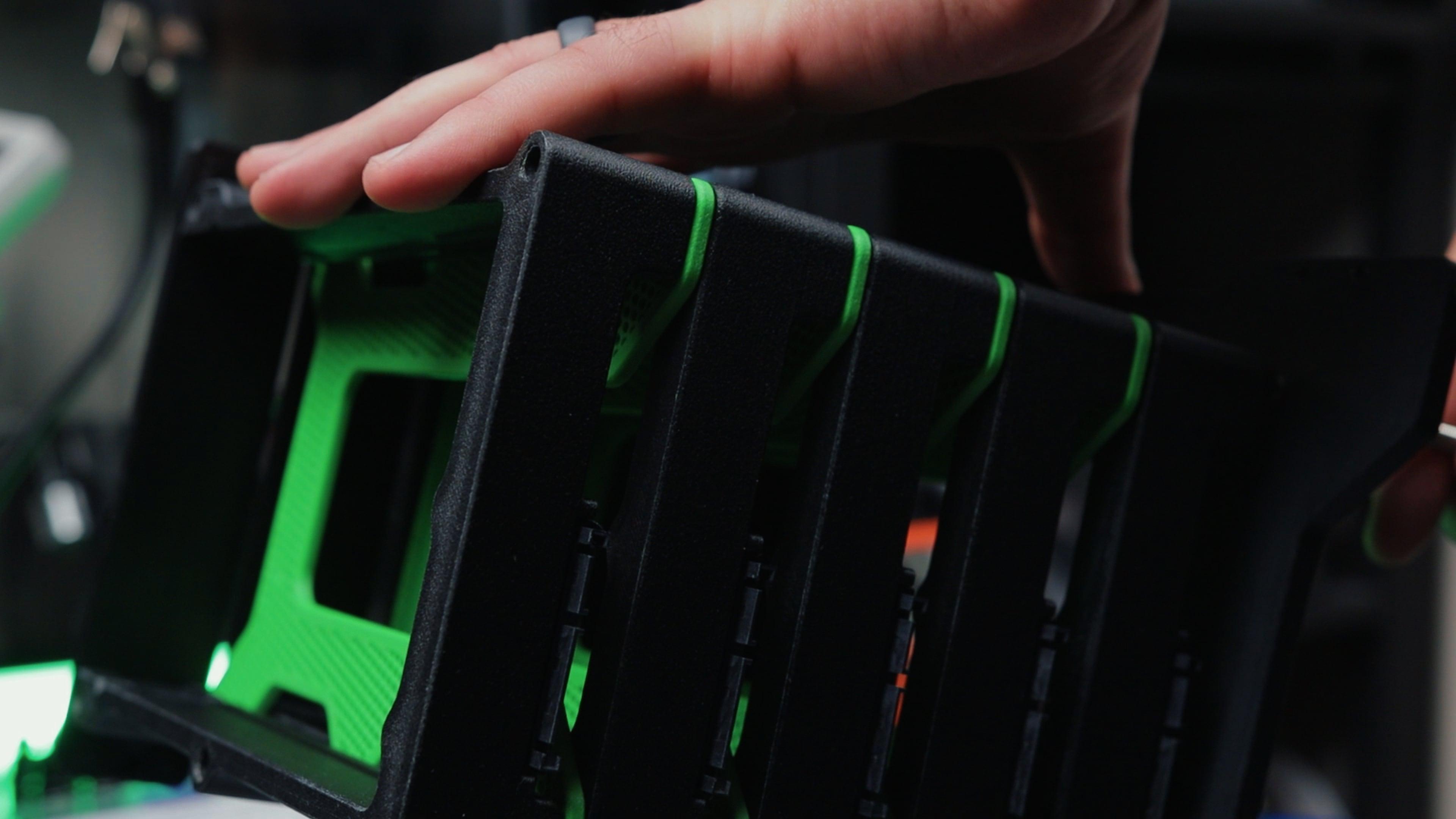
The Drive Cage
Before assembling the drive cage, mount all the SATA couplers to the drive slots using M3 socket head cap screws. After that, you can start assembling the cage.
The threaded rods need to be cut down to around 230 mm and inserted one by one through the side plates. Place 2 nylon washers on each of the 6 rods before the first drive slot and the after the last one. Add one washer between each drive cover and the green separators. I found that the friction from the washers alone was enough to keep the covers tight and aligned, so I didn’t need to place magnets like initially designed to hold them open or closed.
As shown in the video, the process is easier if you thread the rods a little bit after each drive slot to avoid them catching on the sides and making sliding the component difficult. Once the second side plate is in place, add the M6 hex nuts at both ends but leave them loose for now.
To keep the drive cage square and reinforce it, attach the two top brackets using 8 x M3 countersunk screws. Then slide the entire cage onto the base and secure it from the sides using more M3 screws.
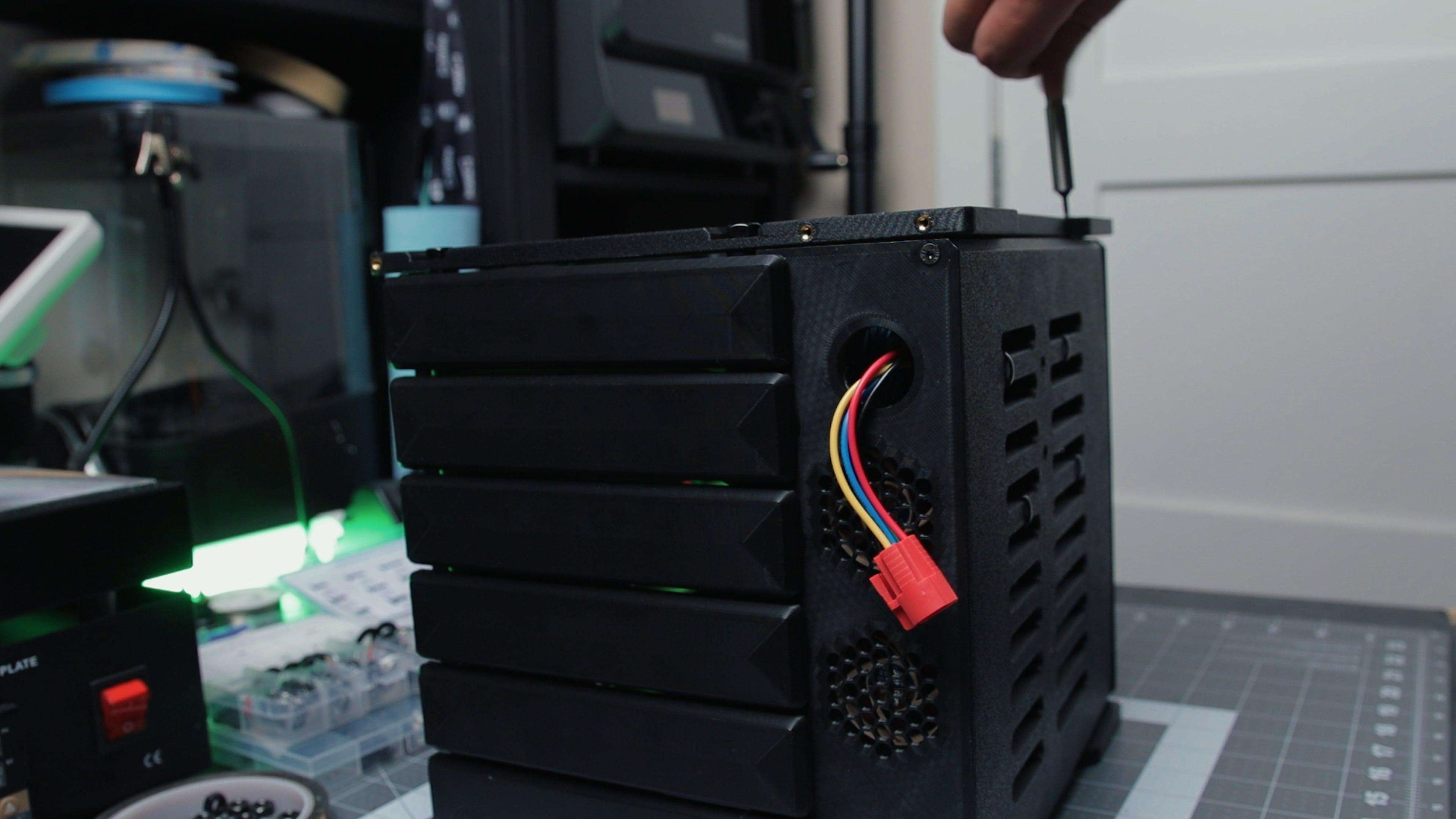
Final Assembly
Mount the two main cooling fans in their housings, making sure they are facing the correct direction. Look for the small arrow on the fans and make sure it points toward the drives. Then mount the fan plate to the back using M3 countersunk screws. After that, install the back IO plate to cover the ZimaBoard and adapter PCB.
Before attaching the outer mesh panels, test the alignment of the drive caddies by sliding a few into place. You should hear a click when they dock properly.
To finish the front, install the power button using the provided nut on the front mesh and plug it into the cable harness that was routed earlier through the base.
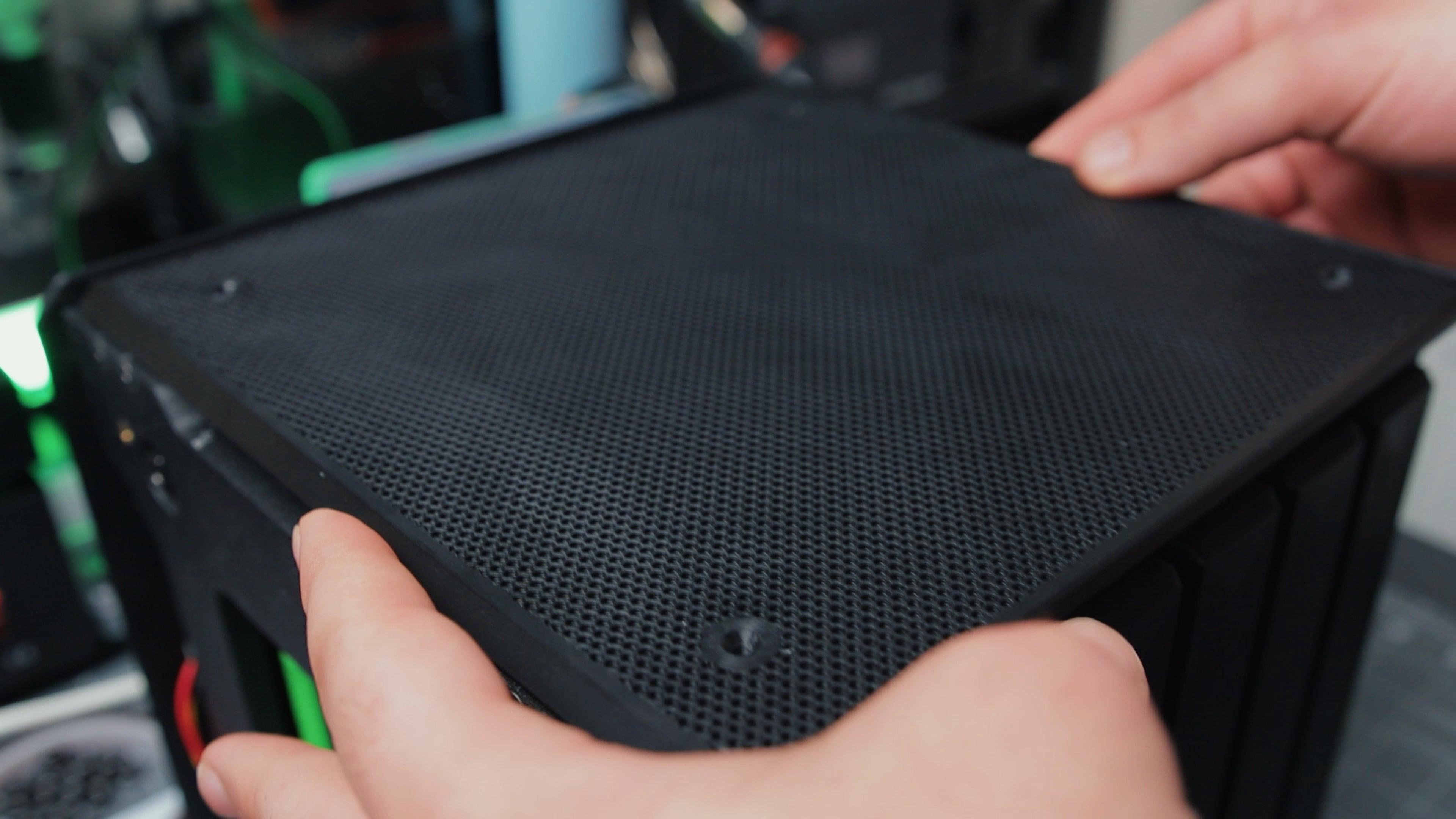
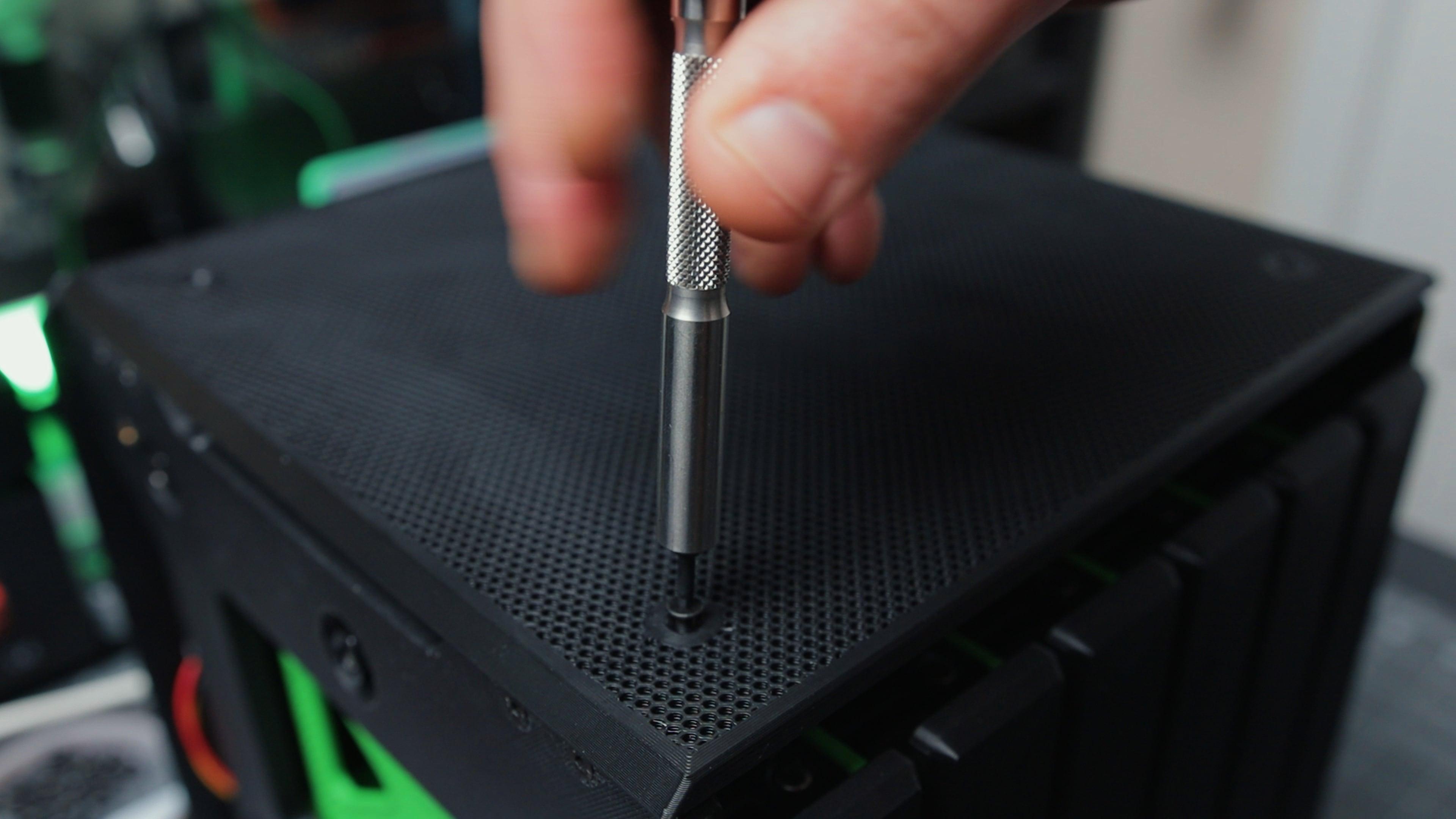
All that’s left now is to secure the side, top, and front mesh panels with countersunk M3 screws.
Done
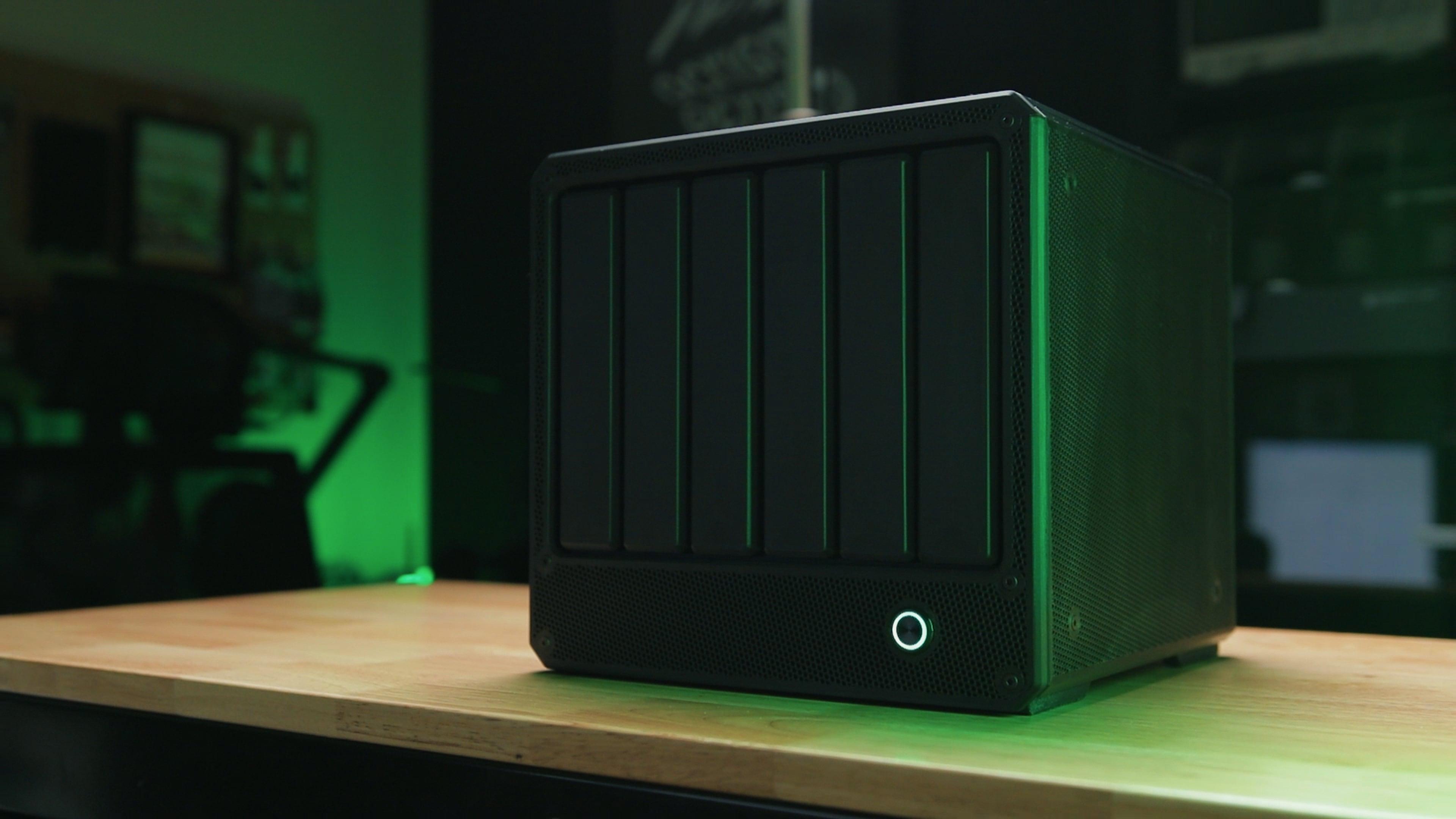


That's it for this one you're done! Thank you for sticking around until the end.
I have other ideas and I plan on making projects like these Follow me for more.