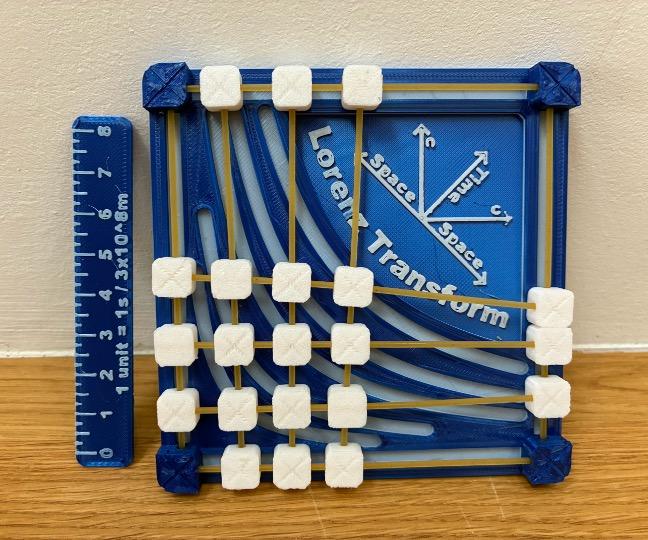
3D Printed Mechanical Lorentz Transform - Visualize Spacetime
by 3DPrintingEnthusiast in Design > 3D Design
899 Views, 5 Favorites, 0 Comments
3D Printed Mechanical Lorentz Transform - Visualize Spacetime
A recently rewatched a video from the science channel minutephysics in which Henry Reich explains what Lorentz Transformations are and how you can use them to explain a lot about spacetime, time dilation, reference frames, and other weird quirks of Special Relativity : https://www.youtube.com/watch?v=Rh0pYtQG5wI. These topics are essential to understand how the universe works and why space and time are actually like two sides of the same coin (spacetime). However understanding the fundamental principles of special relativity may seem incomprehensible for the average person and complex equations do not make everything easier. To facilitate the comprehension of these concepts, minutephysics even had a mechanical model made from steel. It could do a Lorentz transformation for him without the need for complex equations and really made the topic very visual and intuitive. His model however was not for sale and could not be made by the average hobbyist (at least I don't have easy access to a CNC machine and precision components) and so I decided to make my own, with 3D printing of course.
I'm a 9th grade student at the Maria von Linden Gymnasium a high school in Germany.
Download the free stl files here : https://www.printables.com/model/1444013-lorenz-transform-simulator
Supplies


Tools:
- Autodesk Fusion
- 3D Printer
- Hot glue
Materials
- Any rigid 3D printing filament
- Spagetti
Time Dilation
Ever since Einstein devised Special Relativity and General Relativity we've known that space and time are linked to form spacetime.
Say you are in a spaceship moving at 3 m/s and you threw a ball out at 5m/s, you would see the ball moving away relative to you at 5m/s, but another person not moving at all would see both velocities (spaceship speed + ball speed) combine and would see the ball moving out at 8m/s. This is normal and what we would expect from everyday life. Now if you were to replace the ball with a single photon (light particle) traveling at the speed of light and you would still see the photon move away from you at the speed of light. Now the interesting part is that the external non-moving observer looking at the photon would see it moving also at the speed of light (and NOT the speed of light + the speed of the spaceship). This intuitively creates a paradox but that is solved by realizing that time and space are linked. The clock of the observer would therefore tick slower as seen from the person on the spaceship.
If this wasn't weird enough already, something interesting happens when we take into account that all motion is relative. It doesn't matter if the ball is moving away from you or you are moving away from the ball, the physics stay the same. Through this you could argue that the person in the spaceship is stationary and the external observer is the one who is moving. Taking into account that when a person moves their clock ticks slower relative to a stationary observer the spaceship person would see the external one's clock tick slower. So both see that the other's clock ticks slower. This is called time dilation and it is the fundamental principle that causes so many weird things like the twins paradox and the clock paradox.
Lorentz Transformation
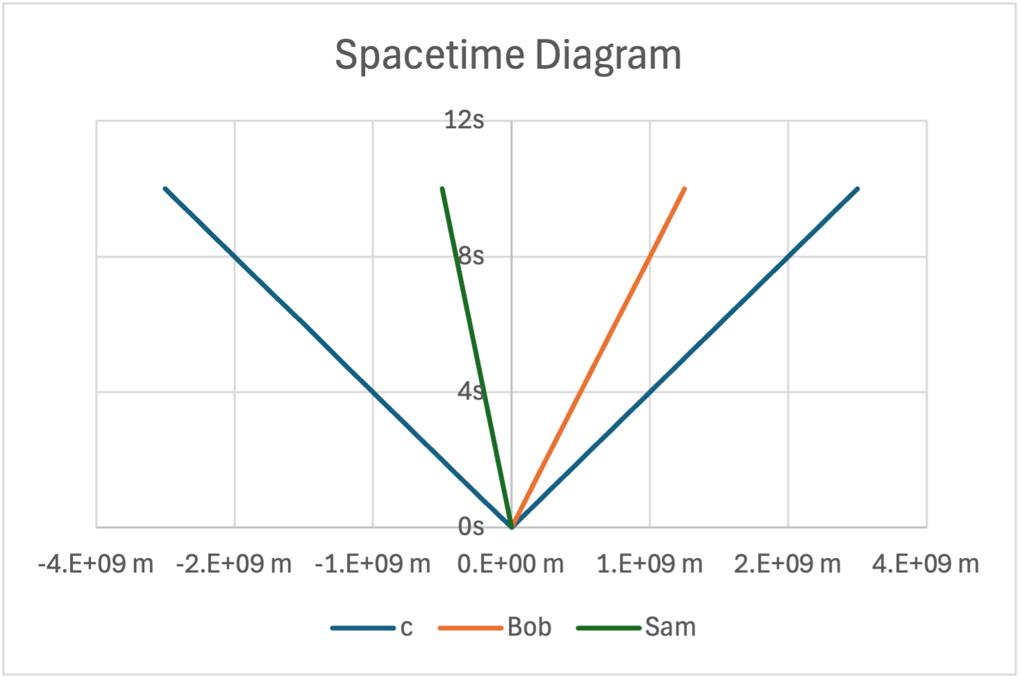

To visualize spacetime people usually draw Spacetime diagrams in which the x axis is space and the y axis is time. Your reference point (usually you) is a straight line along the y axis and the speed of light is drawn at a 45 degree line from the origin. Any other things/people moving away from you are drawn respectively. Notice that the slope of the line directly correlates to the speed. If the slope is 45 degrees to the y axis the thing is moving at the speed of light, if the slope is less than 45 degrees to the y axis then the thing is moving slower than the speed of light. Now because of special relativity you should be able to transform one diagram into another (to see how everything would look from Bob's perspective for example in image 1) but because of time dilation you can't just simply rotate the graph around the origin or slide all the lines across and keep the y values because that would mean the speed of light can be different but it is always the same. Instead you have to do something called the Lorentz transformation in which you use complex math and equations to squish and stretch the graph in certain ways to keep the speed of light constant but change the other speeds (see the second image). This explanation is highly abridged and I do recommend watching the video that inspired me to make this by minutephysics : https://www.youtube.com/watch?v=Rh0pYtQG5wI. This transformation is what I wanted to recreate mechanically with 3D printing.
Sketching
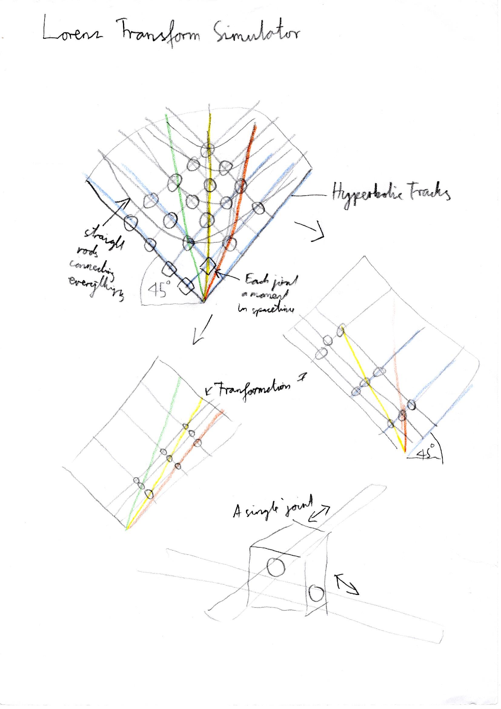
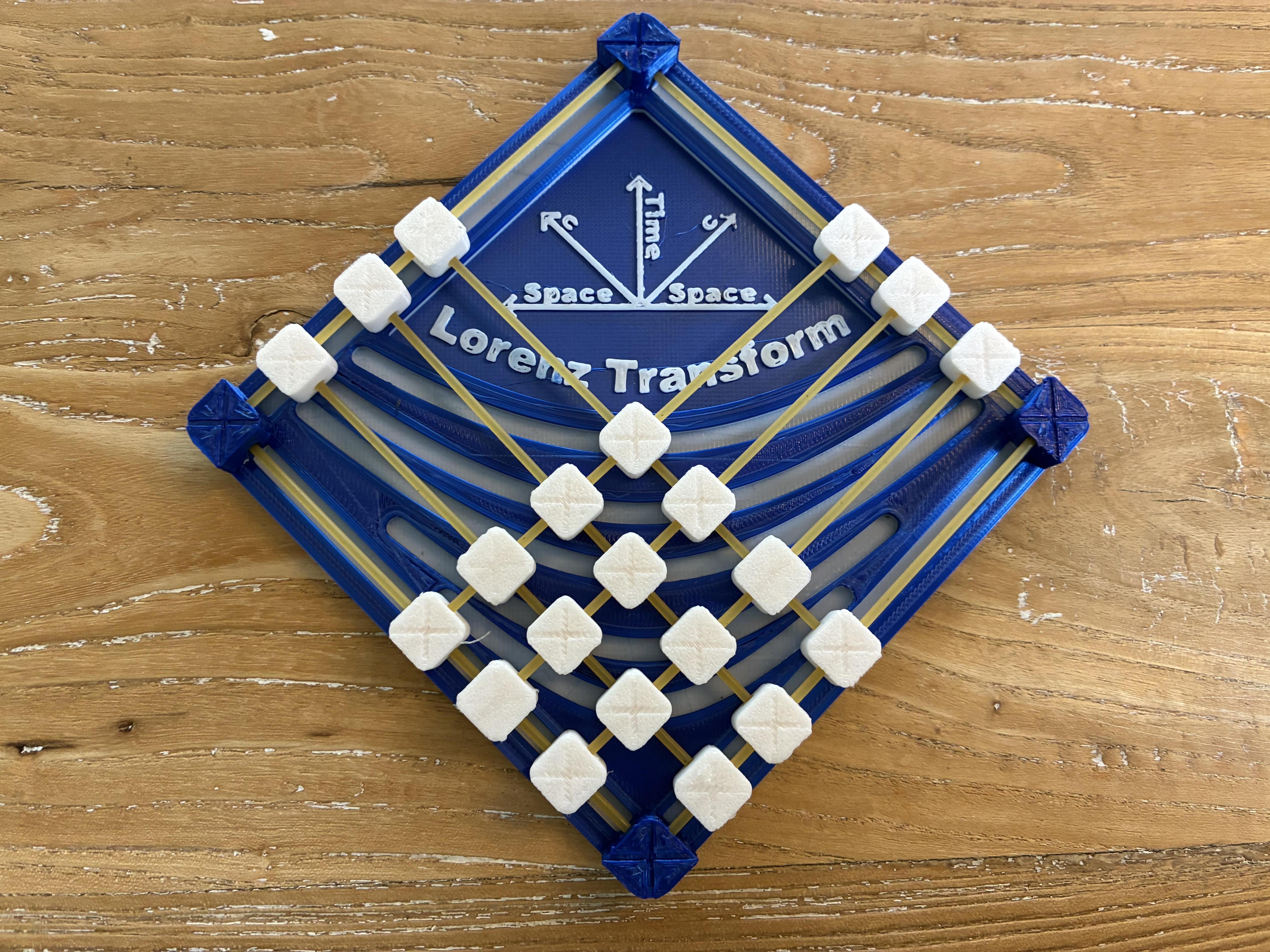
To start off the design I first had to conceptualize how the mechanism would work. For one thing the speed of light is always represented by a 45 degree angle and each point in a Lorentz transformation follows a hyperbola. These two constraints already give you the Lorentz transform and a way to create it mechanically. 45 degree and -45 degree angled rods form the general lattice (1st constraint). At each intersection a mechanical joint is placed to keep the structure rigid. Then the mechanical joint doubles as a pin for a hyperbolic track in the baseplate (2nd constraint). This way when you push on one of the joints, all of them should move and adjust to the mathematical Lorentz transform. My design would be considerably smaller than the one minutephysics had (for practicality reasons) and so the rods had to be scaled down as well. This would later lead to unexpected problems.
The General Design


- I started the design with a cuboid with two perpendicular holes in it which I then patterned to form a 6 by 6 lattice structure
- Next I graphed the points for the different hyperbolas and used those sketches to extrude the corresponding hyperbolic tracks
- Then I added straight tracks along each of the edges to keep the structure held in place while in use
- After that I added the pins that would slide in the tracks to the specific amount of posts that required this
Finishing Touches


- To save material, I removed the big empty triangle and replaced it with some information on how to read the graph (labelled axes and units)
- To further keep the structure in place (since I was using small rods instead of big steel ones) I added a dovetail design to the tracks on the end. This would eliminate the need for a top plate and reduce print time and material.
- I then fixed all the edge joints for the rods in place on the base (since they wouldn't move) and finished everything off by filleting and chamfering the edges
Printing and Assembling
Everything printed nicely but I did have to fine tune the clearances for the rods I was using a lot (2nd pic). The rods were the next problem. I needed something accessible to everybody but accurate and sturdy enough to function well enough. In then end I decided on uncooked spaghetti noodles which had their own unique set of problems. But once I had printed everything and assembled it, the result wasn't really great. It did recreate the Lorentz transform mechanically but was otherwise really terrible. For one thing it literally took over 2 minutes to do a Lorentz transform and it would constantly jam up and you'd have to constantly nudge the jammed pieces forward minute amounts. I tried lubricating it and it did help but the mechanism still jammed up. To fix some of the problems I removed the dovetail feature on the outer tracks and this did help and I could now do a Lorentz transform in around 40 seconds but this was still too much. In addition to that the footprint was still a bit large.
Improvements
For the second version I decided to cut down on friction immensely by using a 4 by 4 grid instead of a 6 by 6 grid. This would reduce the resolution of the Lorentz transform, but would still be enough to demonstrate the main ideas like time dilation and the relativity of simultaneity. This would also reduce the size of the device. The next improvement I wanted to add was flattening the joints to make them less top heavy and reduce the torque from something jammed pulling off center. Making the joints wider also would have the added benefit of having less flex laterally.
Designing V2


I quickly started implementing these improvements but the original design had a very messy timeline so I decided to start from scratch again. The design process was very similar and so I knew what to do.
- Again I started by creating a single joint with two perpendicular holes in it (this time wider and thinner)
- To aid in measuring the distances and the time I added cross marks onto the joints to provide an accurate reference point
- This structure was again copied for for the entire grid (4 by 4)
- Next I created the smaller baseplate and sketched the hyperbolas onto it
- After that I finished the tracks and fixed the 4 edge connections in place to the baseplate
Finishing V2


Now I started to work on the finishing touches
- I started by adding fillets to make it look nicer and print more accurately and added a generous chamfer on the bottom to combat elephants foot (the printing defect in which the nozzle is too close to the bed and the material squishes out sideways giving a squished appearance)
- Then I added the same decals at the top to give some information about the graph and to save a bit of material (although no much since the infill is mostly hollow)
Creating a "Spacetime Ruler"


To measure either space or time I decided to create a 3d printable ruler that matches the spacing used in the mechanical graph (16mm)
- To do this I drew a rectangle and added vertical lines to form the notches for the different measurements
- Then I added some information as to what a single unit represents (1s vertically or 3 x 10^8 m horizontally)
- This sketch was then used to form the ruler using a variety of different extrudes and thin wall extrudes for the notches
After printing I however noticed an error. I was supposed to use a spacing of sqrt(128)mm (the diagonal of a square with side length 8) instead of 8mm (the side length). This meant I had to update everything and print it again.
Printing


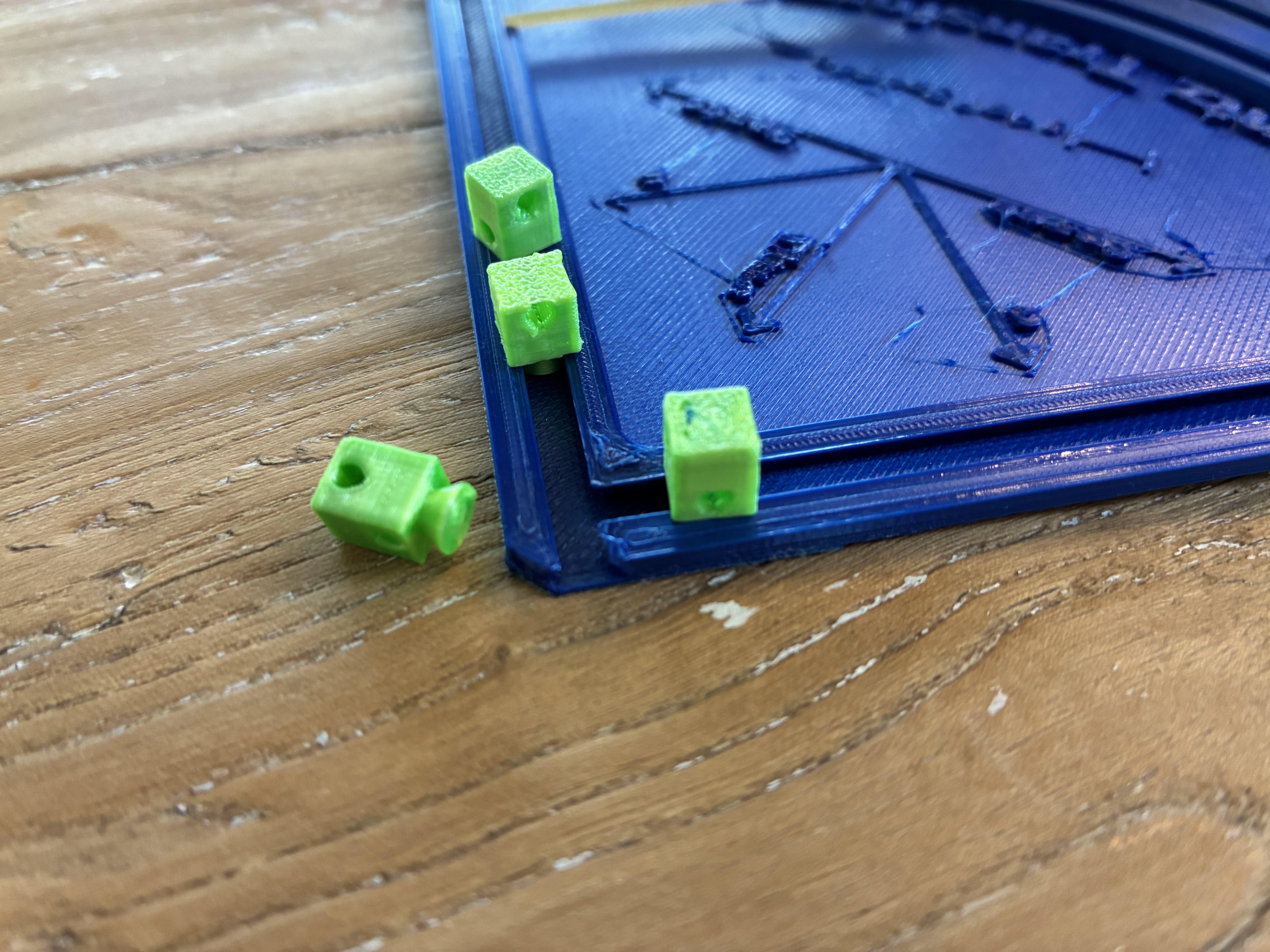
Everything printed well but the accuracy of the 3D printed joints was off. I changed a few parameters but either the hole was too big creating a sloppy loose fit, or the hole was too small and the shaft wouldn't slide freely. I had already printed a whole bunch of test parts when I realized that the shaft would always slip through one side but jam up on the exit of the hole. There must be some printing defect there and I suspected it to be the seam. Sure enough when I looked at the slicer preview, I saw the seams being exactly the places where the joint had trouble sliding through. Now I knew the problem but Cura (the slicer I was using) doesn't support paint on seams and their seam placement was just too grainy. In the end I carved little notches into the print to encourage the seam to naturally form there when the seam settings were set to "sharpest corner" and "expose seam".
Assembly
The assembly is actually quite straightforward and involves few steps
Download the free stl files here : https://www.printables.com/model/1444013-lorenz-transform-simulator
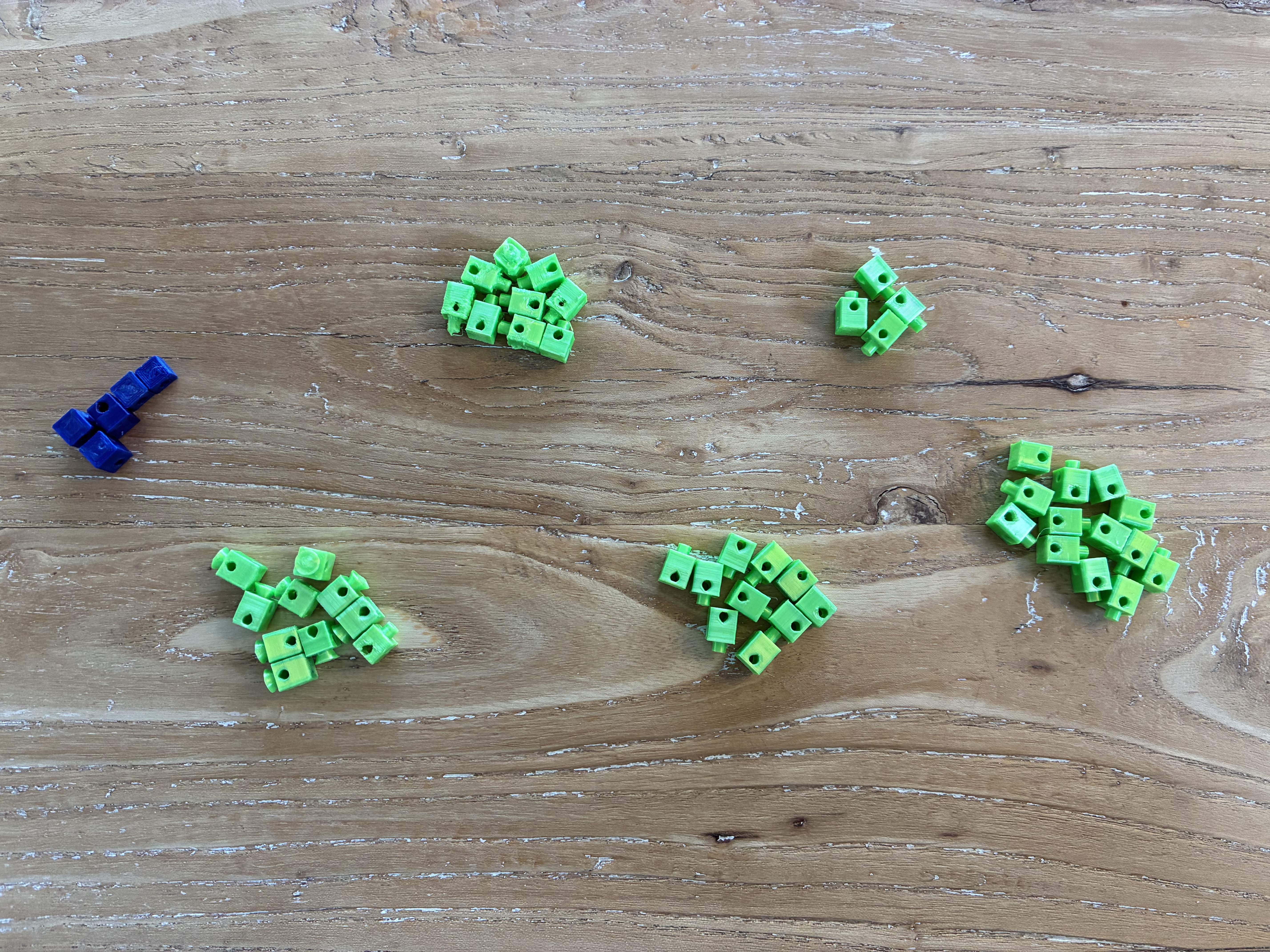
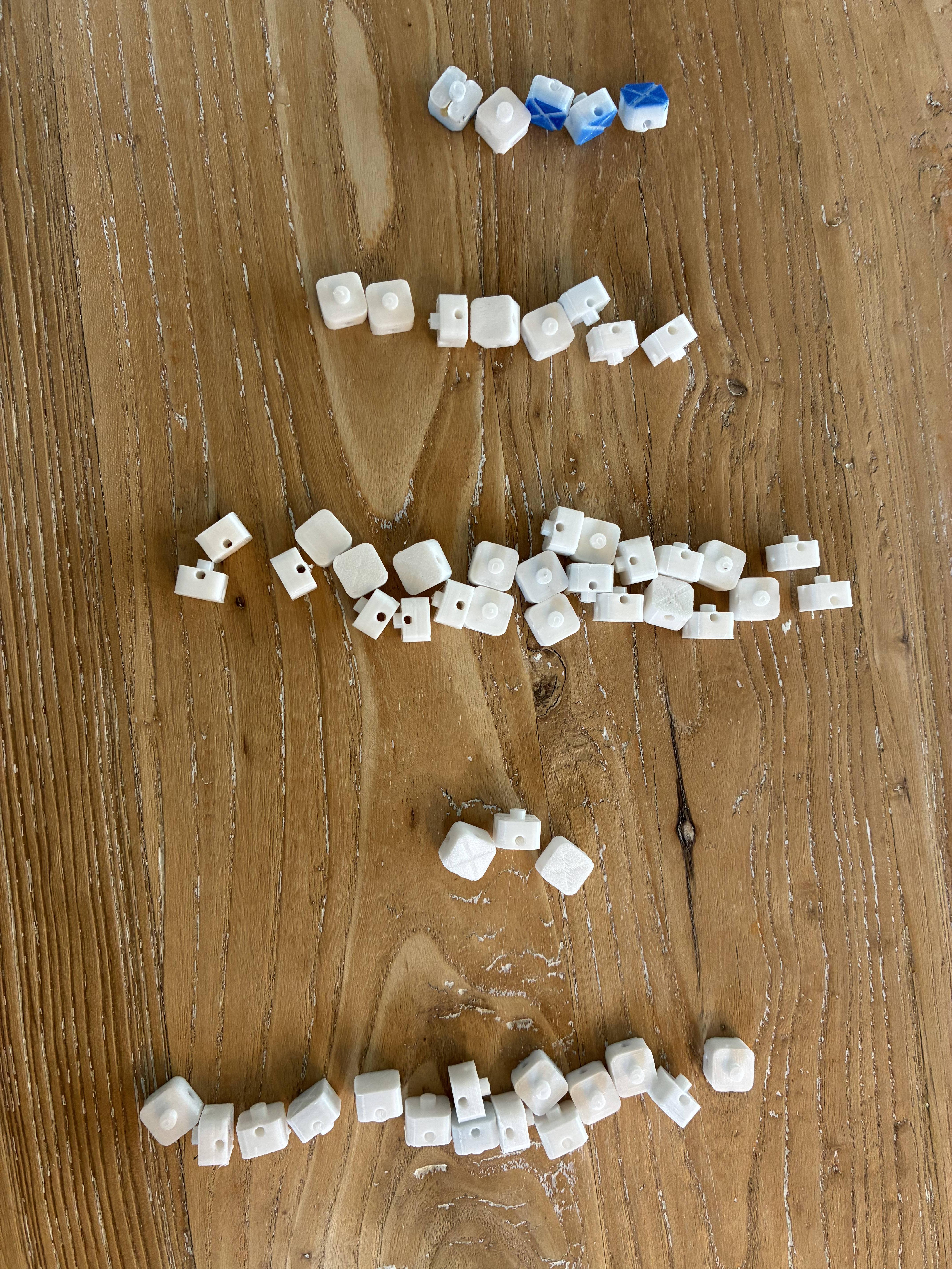
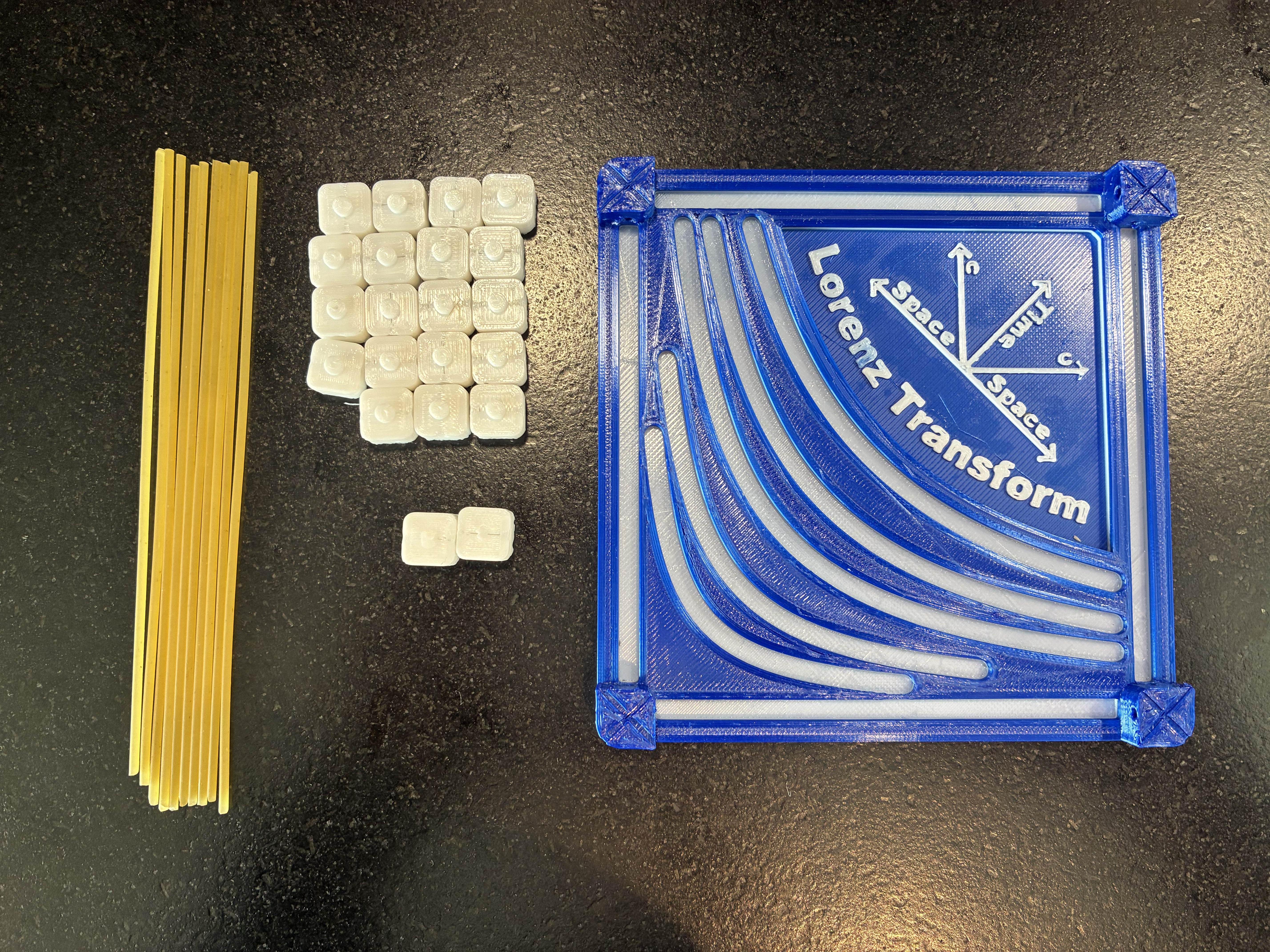
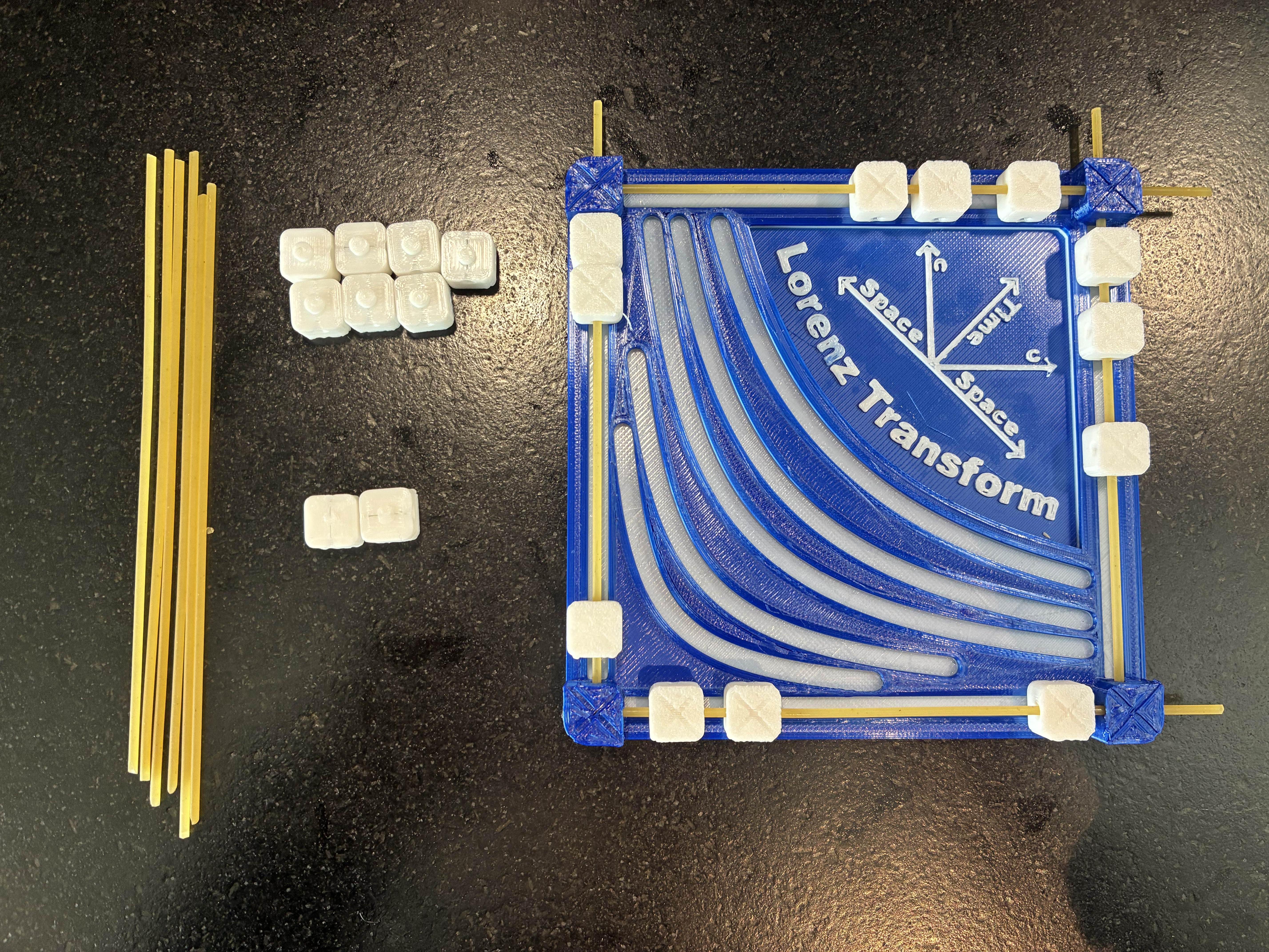
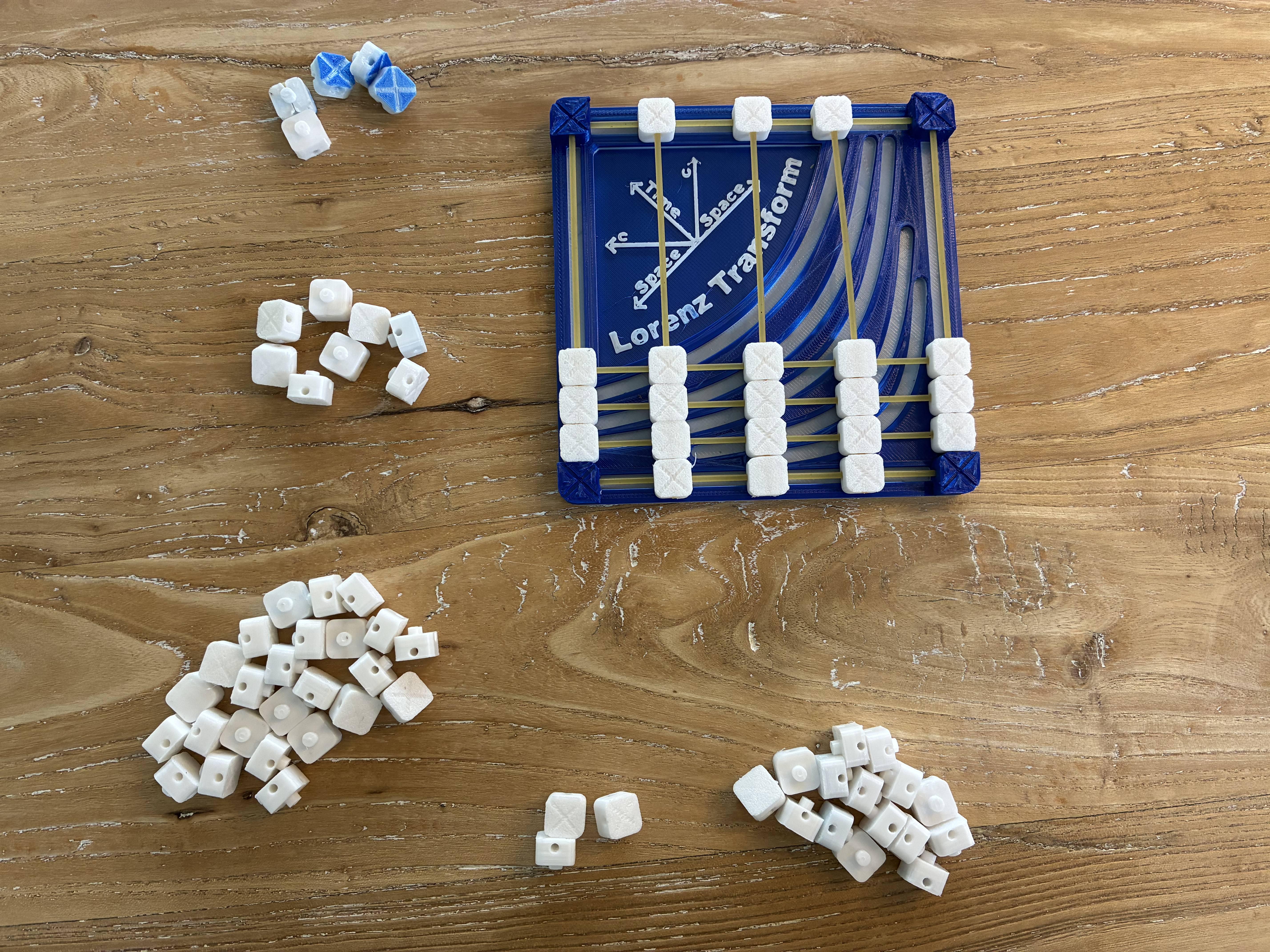
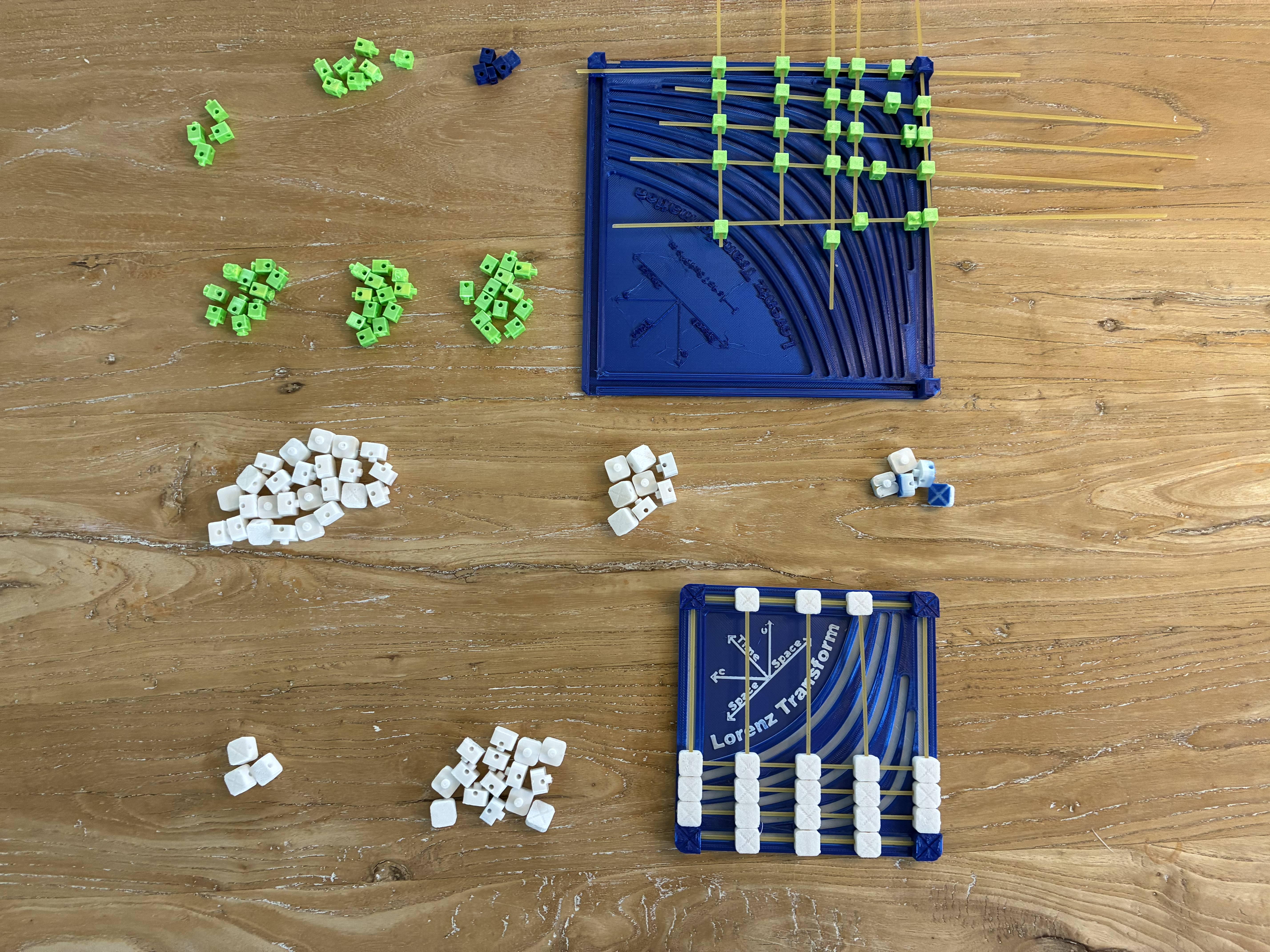
- First, print out the base once, the small joints with pins 19 times and the ones without the pins for the tracks 2 times
- Next, cut down the spaghetti noodles to around 12cm. Make 10 of those
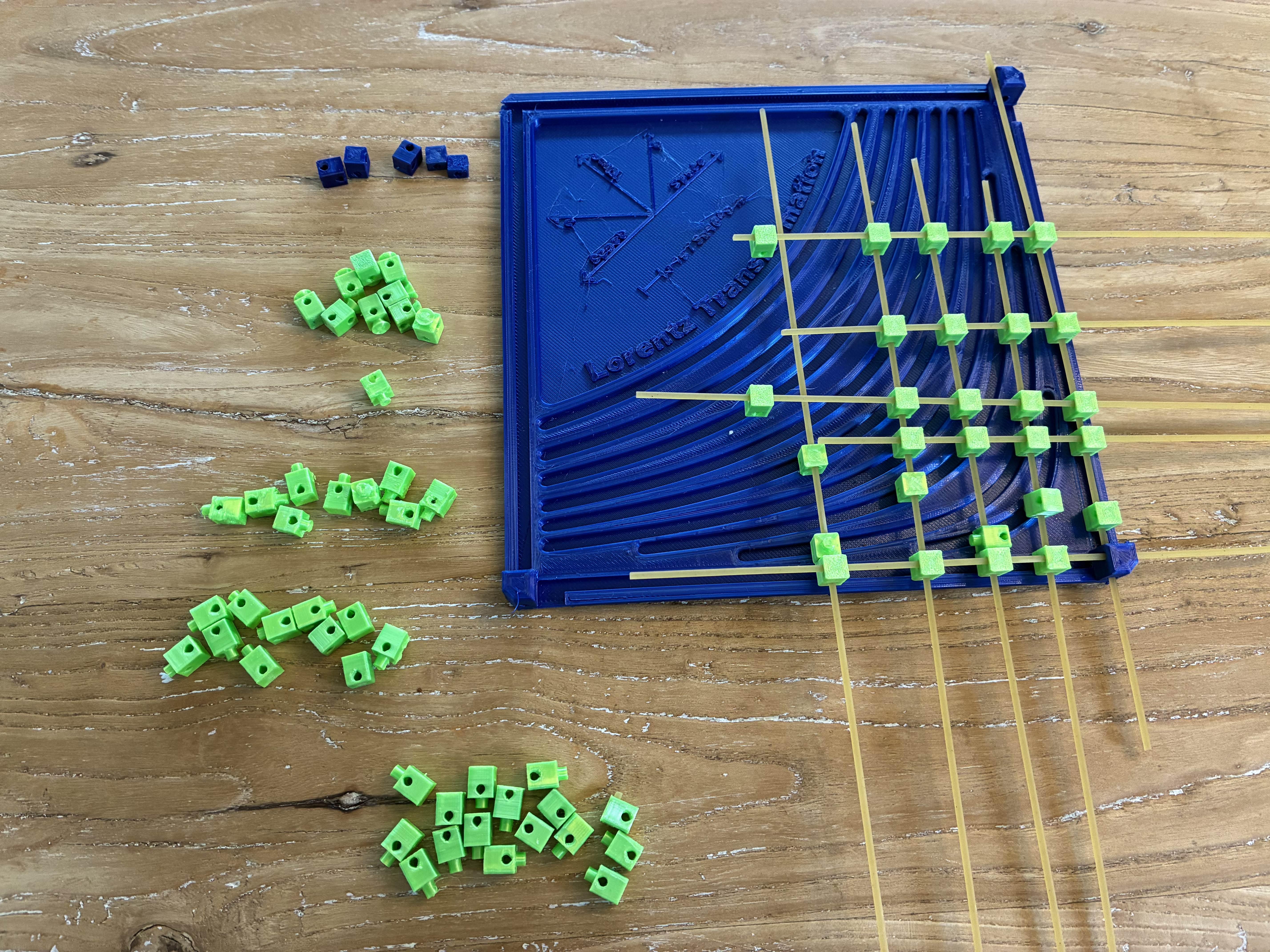
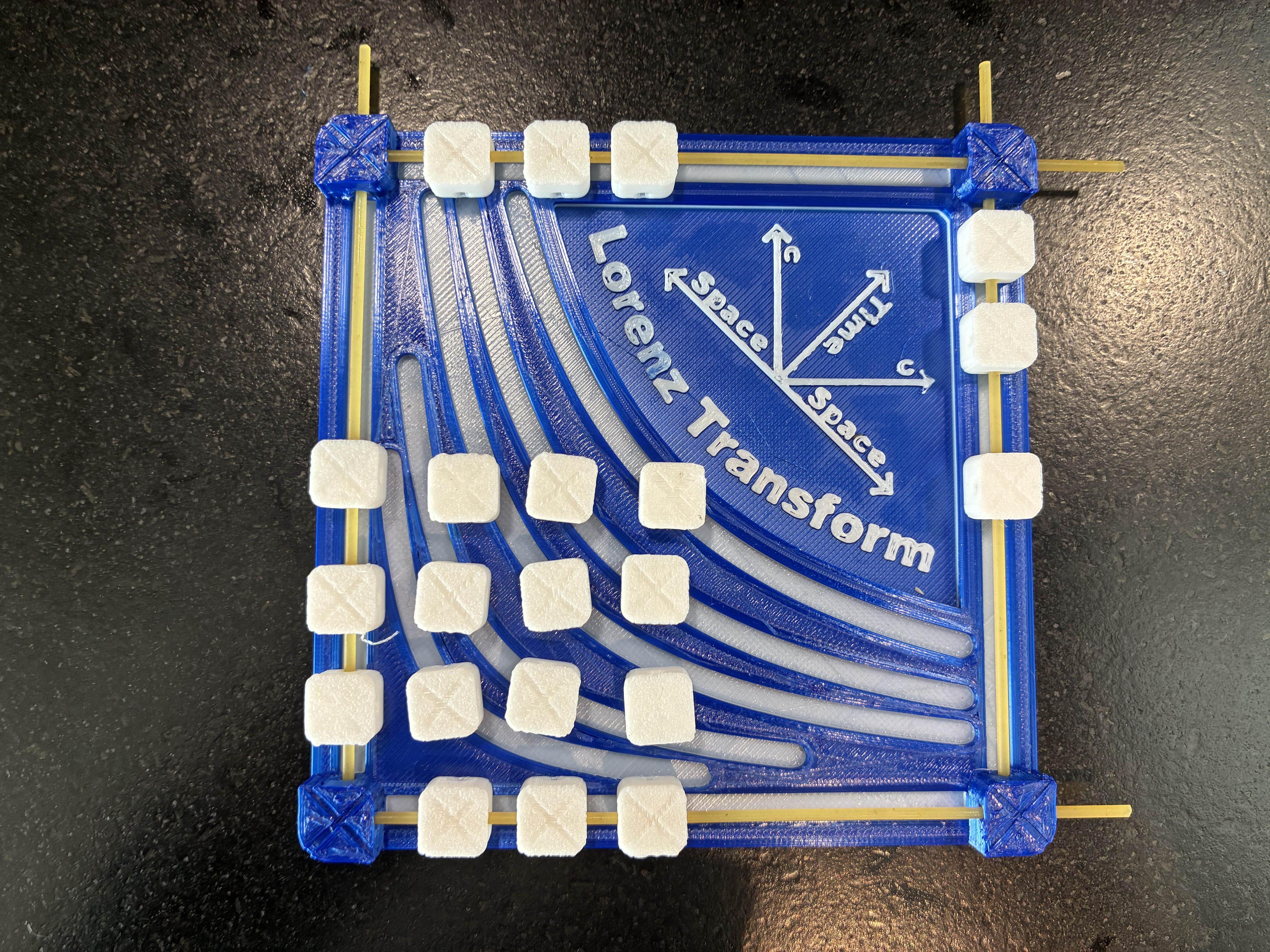
- Now place 3 joints with pins into each track on the outside and fasten them in place using the pre-cut spaghetti
- After that lay out the inner grid of joints (see picture) to form a 3 by 3 grid
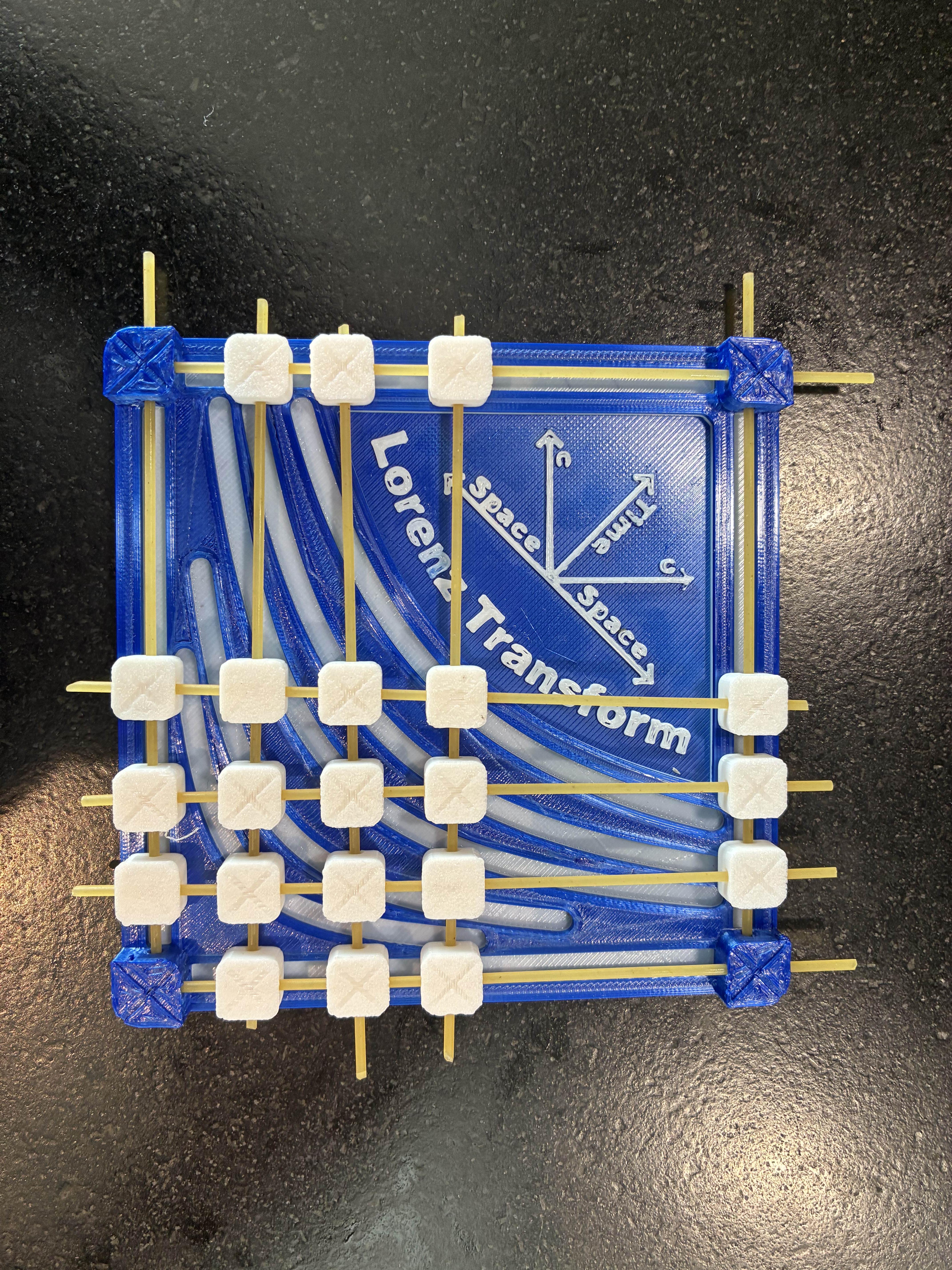
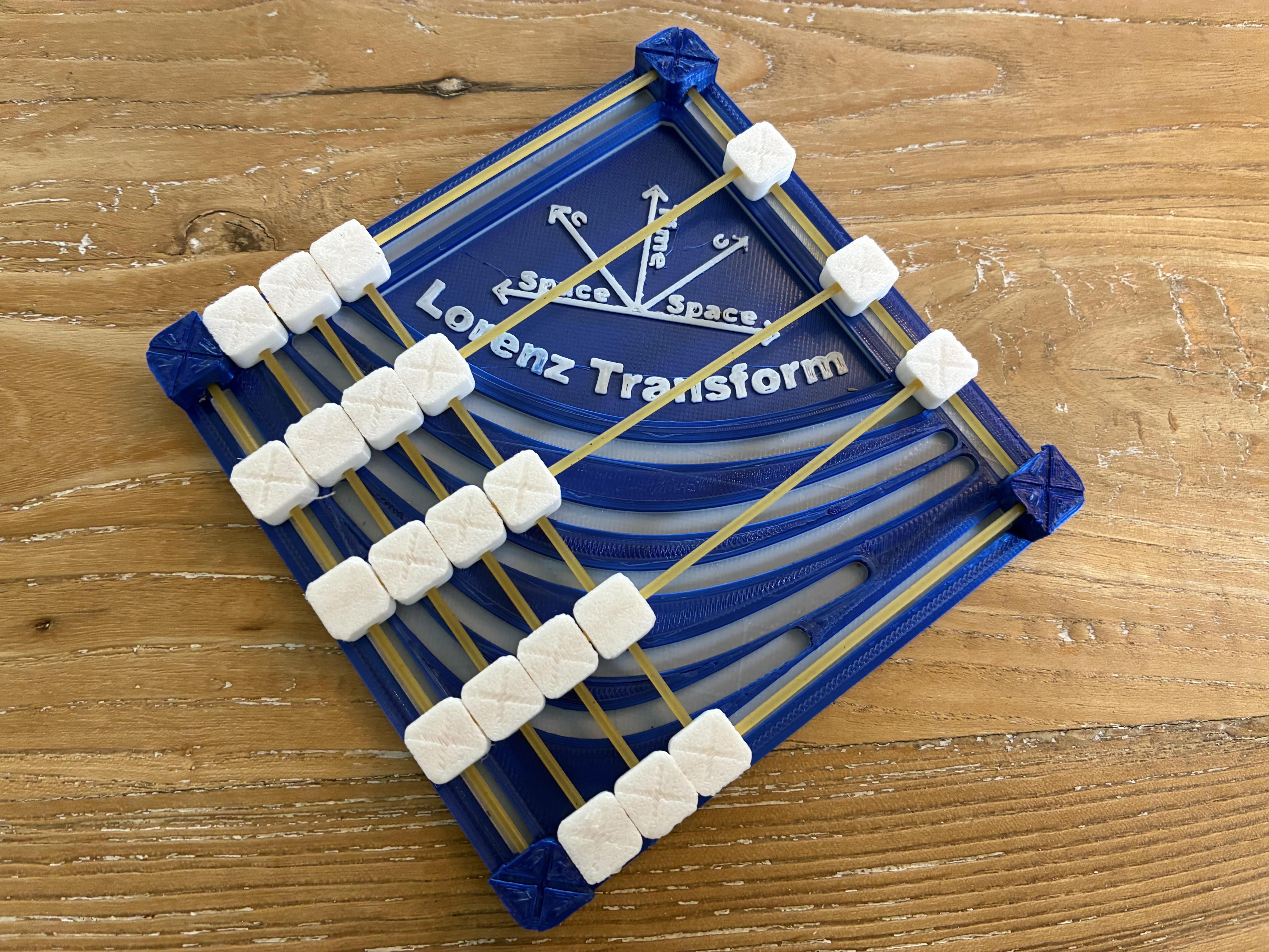
- Once that is done slide the rest of the rods onto the joints and glue the rods in place only with the joints on the outside
- Finally lubricate the tracks for better performance
Testing

This updated design is so much better and although it does jam up once in a while it now only takes around 5 seconds to do a Lorentz transform instead of a full minute. Overall I'm happy with this final result
Example : the Twins Paradox

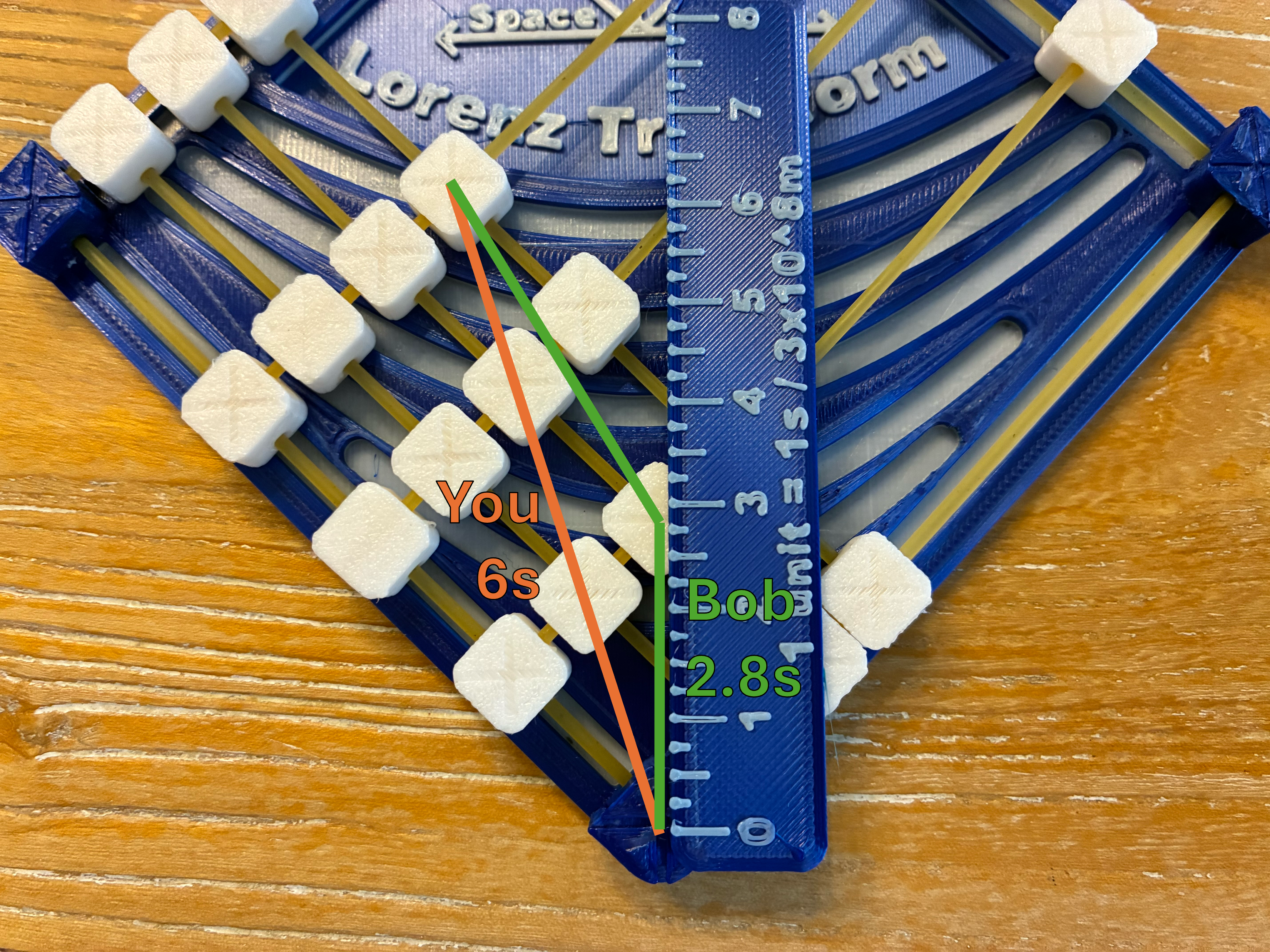
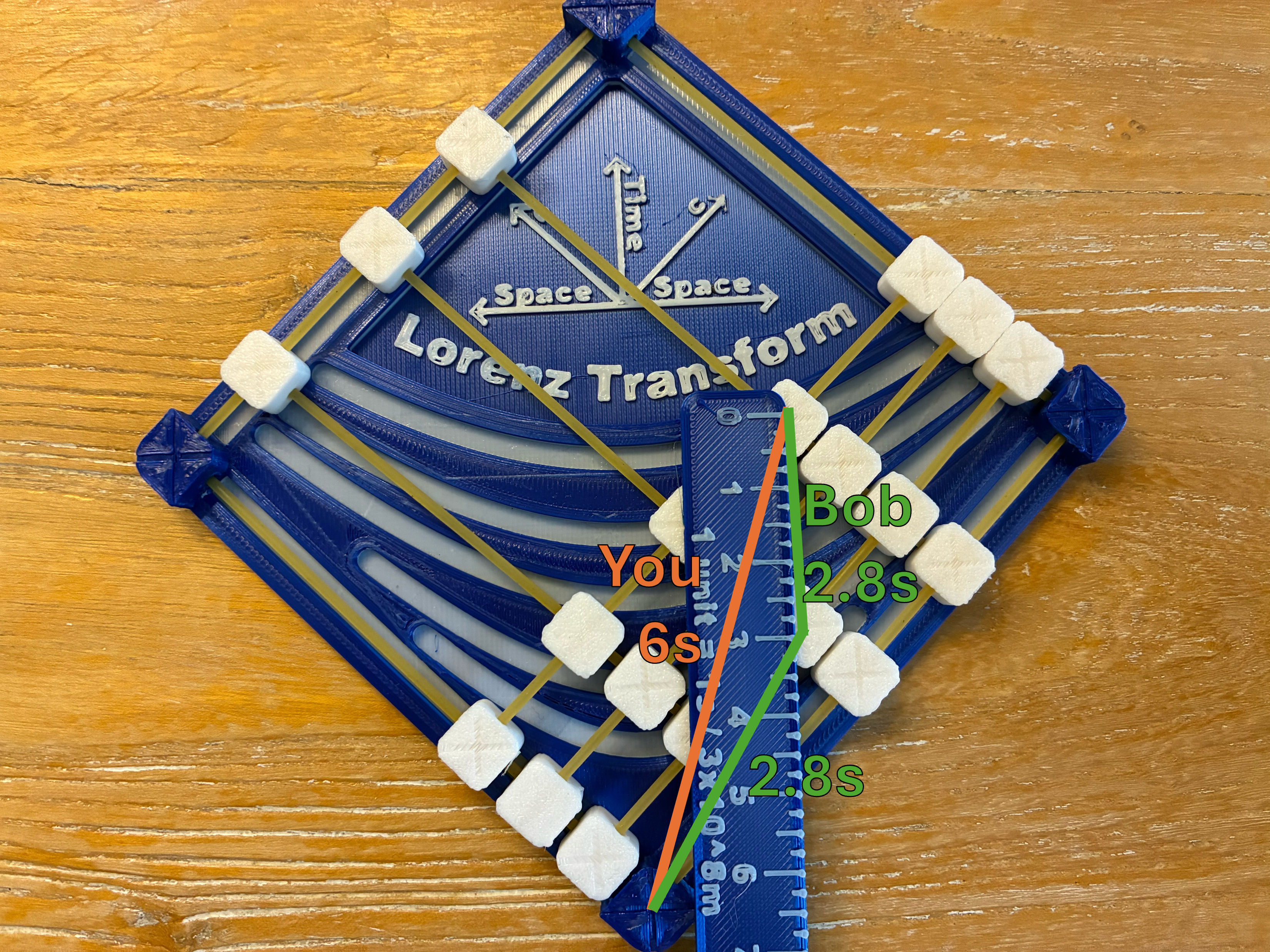
The twins paradox is a great example of the quirks of special relativity and can be explained using the Mechanical Lorentz Transformation Simulator. You stay in place for 6 seconds and your friend Bob starts moving away from you at relativistic speeds (1/3 speed of light). At the halfway point Bob starts moving back to you and you meet at your 6 second mark. Now if you do a Lorentz transform to view if from Bob's perspective using the mechanical model you can measure that he only experiences an amount of time equal to around 2.8 seconds in the first half of his trip. If you use another Lorentz transform you can see that the second half of his trip also only takes around 2.8 seconds from his perspective. So in total he spends 5.6 seconds traveling while you spend a full 6 seconds in standstill. So at the end of this trip Bob is around 0.4 seconds younger. The mechanical model really makes all this very visual and interactive and the real result isn't that far off from reality (time dilation of 6s - (2.828s + 2.828s) = 6s - 5.656s = around 0.34 seconds.
What I Learned
All in all I learned a lot from this project including how Lorentz transforms generally work and what spacetime diagrams represent. I also learned how to control seam placement in the 3D model using small notches for optimal dimensional accuracy. One Autodesk Fusion skill I learned was taking advantage of thin wall extrudes instead of offsetting curves in Fusion and then extruding that.