3D Printed Optical Telegraph Model
by andrei.erdei in Circuits > Arduino
6685 Views, 38 Favorites, 0 Comments
3D Printed Optical Telegraph Model

In this project I would like to present you a model of the optical telegraph invented in France by Claude Chappe in the 1780s. The first official presentation of this type of communication was presented on March 2, 1791. Since then, for almost 70 years, the system developed a lot but after 1850 it was replaced by the electric telegraph.
In essence, Chappe's system consisted of a network of towers similar to those of windmills, built at distances in the field of view of the optical telescopes at that time, about 15-25 km. On every communication tower was placed a vertical pillar to which a crossbar was attached. Two arms were mounted at both ends of the crossbar. Both the crossbar and the arms could be rotated independently by means of an actuating mechanism located in the tower. By rotating the crossbar and arms in certain positions one could encode the letters of the alphabet, numbers or even whole words or phrases from a so-called "dictionary".
This would be a short presentation, you can read more on the wiki page dedicated to the Optical Telegraph. I hope I sparked your interest and if so, you can keep following me :)
Supplies

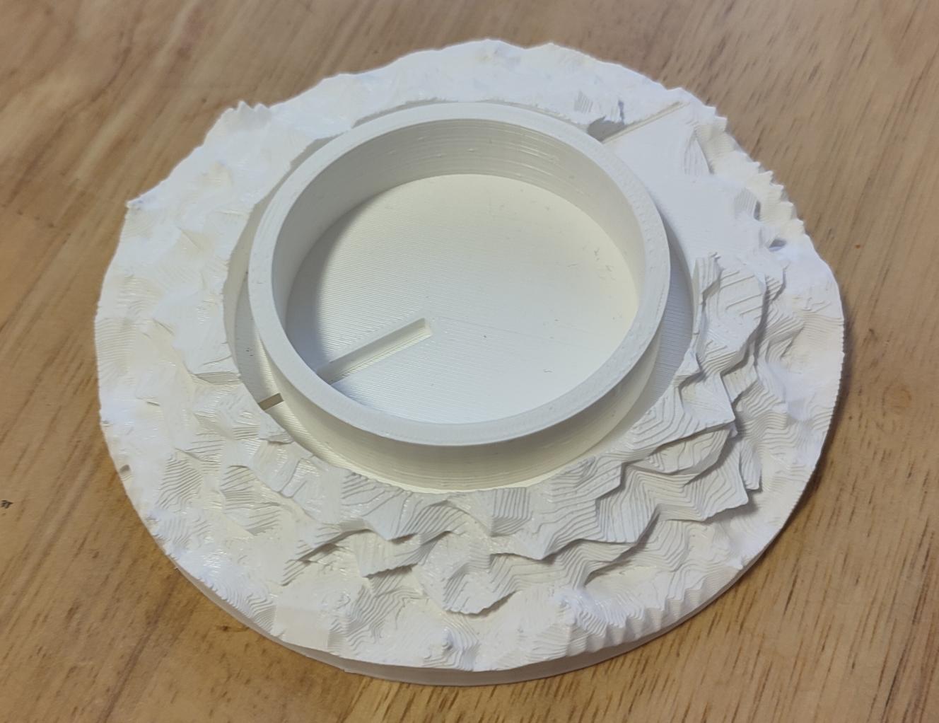
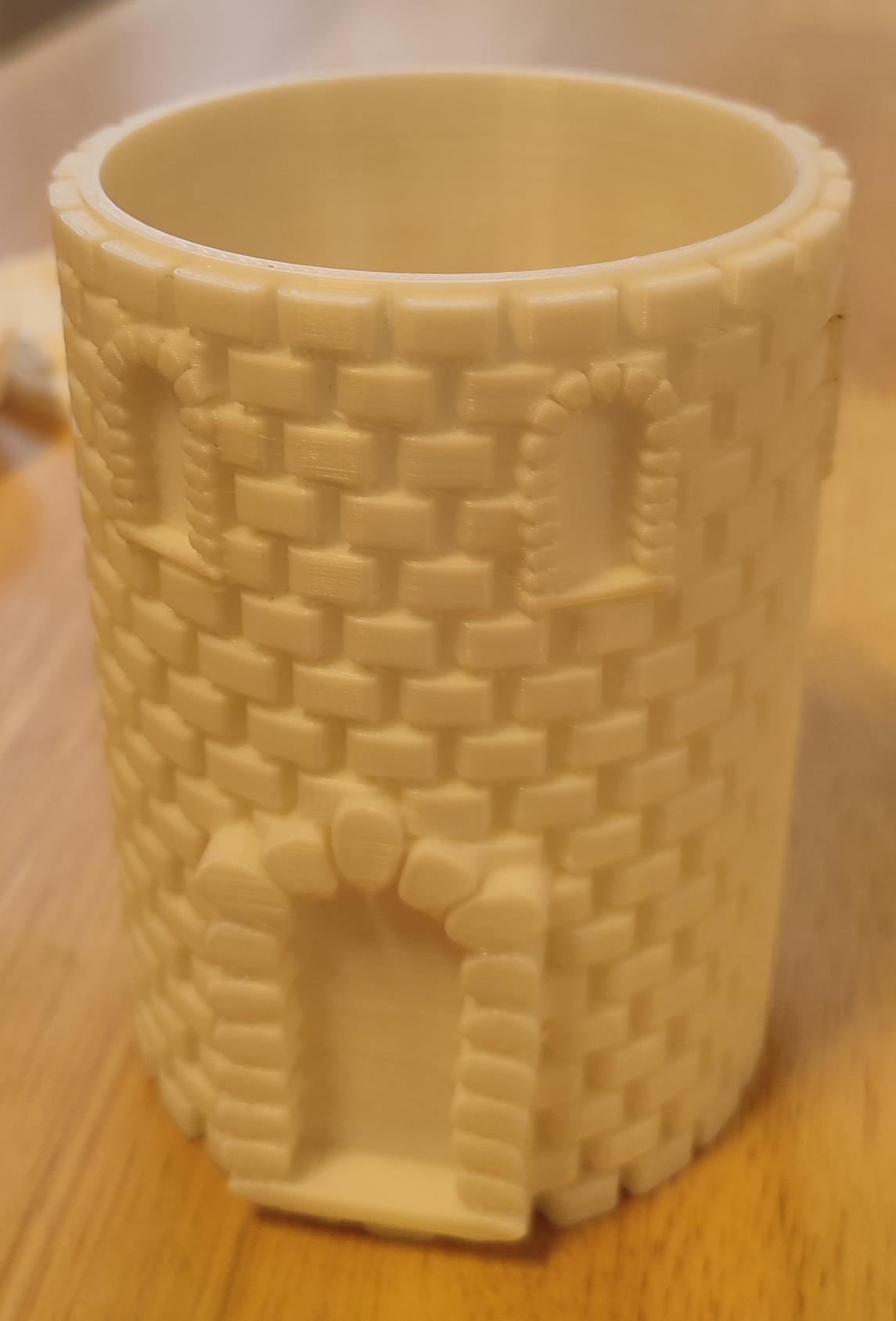
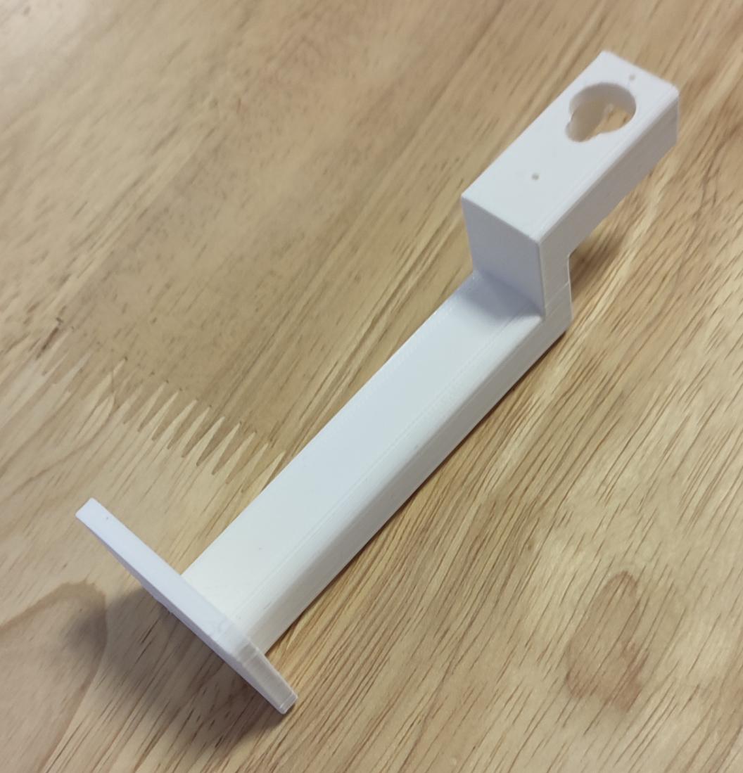


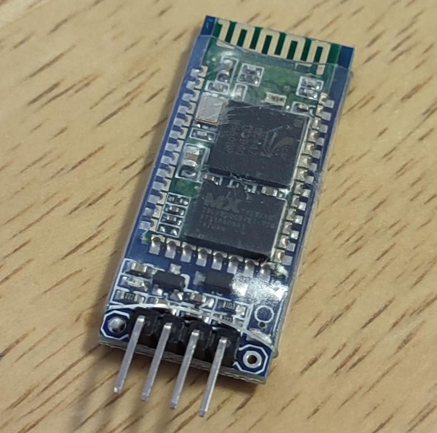



- 3D printed parts (on Tinkercad - part I and part II);
- Acrylic paint;
- Brushes;
- MG90S servomotors 3pc;
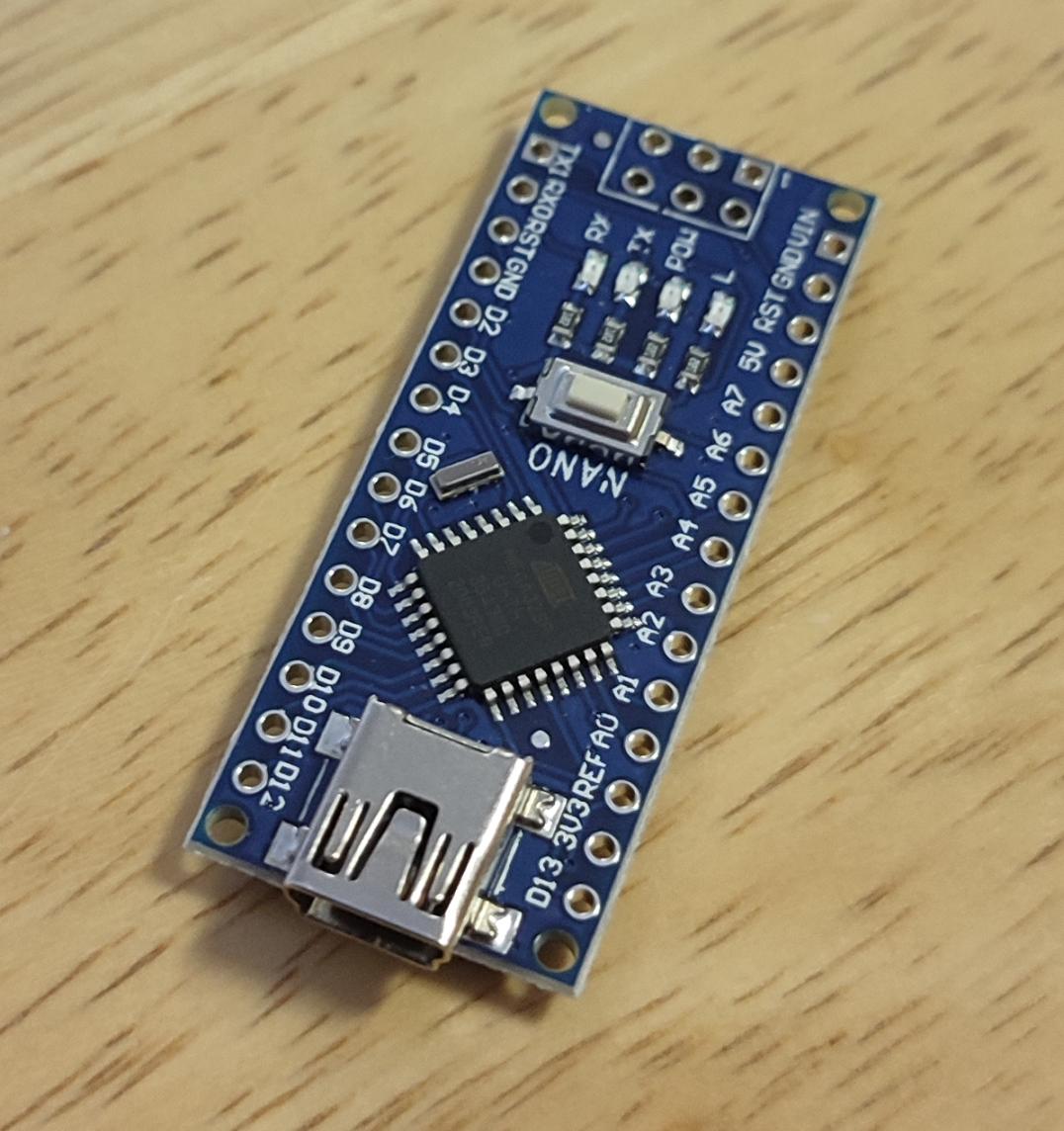
- Arduino Nano module 1pc;
- HC06 Bluetooth module 1pc;
- Power supply 5v /1.5A 1pc
- DC plug 5.5 / 2.5mm with wires 1pc;
- 2 resistors of 2 kohm respectively 1 kohm
- M4 screws and nuts, connecting wires, heat shrinking tubes.
I did not give links for the purchase of components because they are found in many places.
A few words about the 3D printed parts.
I divided the parts on Tinkercad into two projects because they are relatively complicated and editing them would be particularly difficult if they were all together.
The tower cover has rather large overhangs and I used support material but it was very difficult to remove the supports after printing. At the base and body of the tower, although there are overhangs, I did not use supports and still the printing was very good, it can be seen in the photos (and I got rid of the torment of removing the supports :)) )
I did almost all the editing of the parts in Tinkercad, I only made the gaps for the servomotor arms in another editing program because the trapezoidal circular shape generator always gave me an error for the dimensions I wanted.
The cheaper SG90 actuators can also be used without problems, the source code does not need to be changed either, but it is necessary to adapt the mounting dimensions of the crossbar and arms.
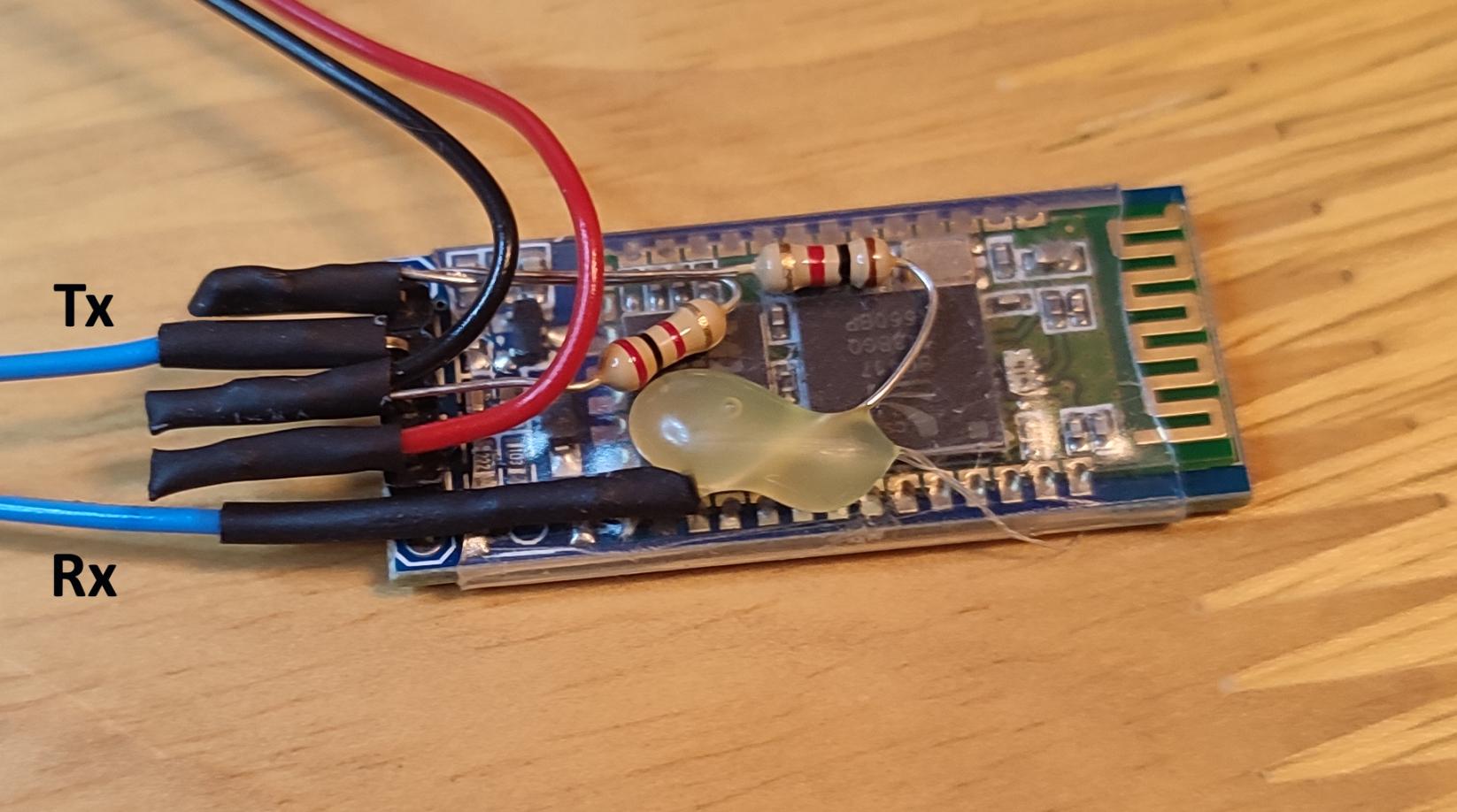
I think you noticed that the Bluetooth module I use is HC-06, a little different from the better known HC-05 module. There is only one difference between them: HC-06 can only work in slave mode, this is not relevant in my project.
The Alphabet
Because I wanted to use cheap servomotors in this project (with 180 degree rotation) I chose for the coding of the alphabet a variant that you can find for example here. Although it seems that this variant was never used by Chappe, according to a Wiki Talk article , I considered it very suitable to show the operation of the optical telegraph. The official code uses several positions of the arms and would need a 270 degree servomotor and I think you know that such servomotors have a pretty high price tag.
For this reason the crossbar will rotate in 4 distinct positions: at 0 degrees, at 45 degrees, 90 degrees and 135 degrees as in the figure below

and the side arms will rotate only in three distinct positions: 0 degrees, 90 degrees and 180 degrees, check the figure below
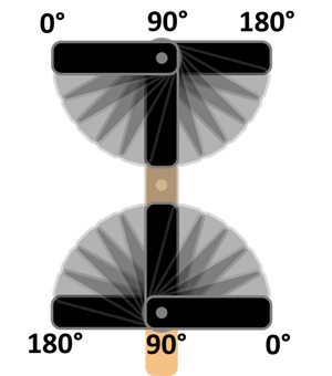
Combining these movements will result in the alphabet (and some numbers) of the optical telegraph as in the following table, very similar to the coding mentioned above.

Interestingly, the letter J is missing from the table. Why? I do not know. I tried to find out why but couldn't find the reason. I would give up “&” and use it as the letter “J” but I preferred “&” to use as a space and used letter "I" for "J" also. This can be seen in the source code.
Also in the source code you will see that I used the exact transposition of these values of the angles of the moving parts of the telegraph, using the “servo” library, an internal library of the Arduino.
An observation...
A variant closer to the original Chappe alphabet would be if in coding I would use the 45 degree positions of the arms and the crossbar only in vertical or horizontal position (the 45 degree and 135 degree position would mean that nothing is transmitted.) It would result in 5x5 + 5x5 = 50 codes, enough for letters, numbers and some special signs.
Electronic Scheme
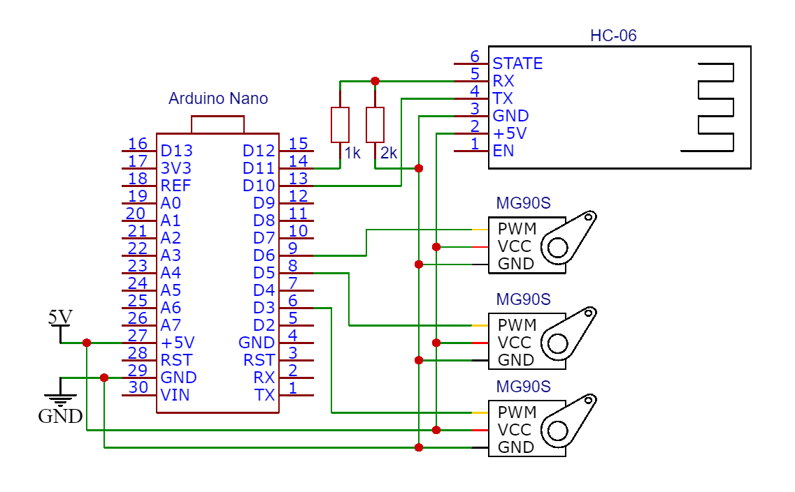
In the graphic above you can follow the electronic diagram.
I would like to make a few remarks about this scheme:
The signal inputs of the actuators must be connected to digital outputs that support PWM. Arduino Nano has 6 digital outputs that support PWM: 3, 5, 6, 9, 10, 11. That's why in my project I use the outputs 3, 5, and 6
The logic levels of the HC-06, TX and RX Bluetooth module are 3.3v. TX is not the problem, for the RX input of the Bluetooth module, the HIGH 5V level of the Arduino Nano must be reduced to 3.3V level . That's why I used a voltage divider made with 2 resistors.
The three servomotors consume quite a lot of current so they cannot be in any way powered from the 5V stabilizer of the Arduino nano module. It is absolutely necessary to feed them separately.
Construction
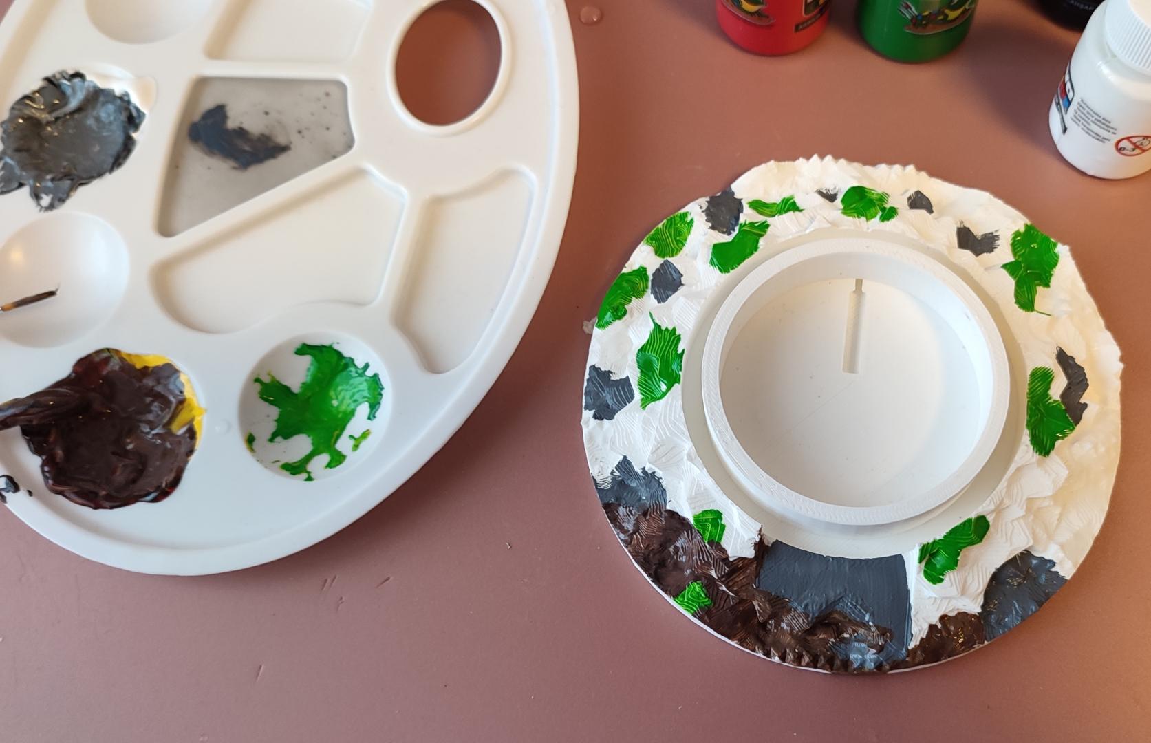


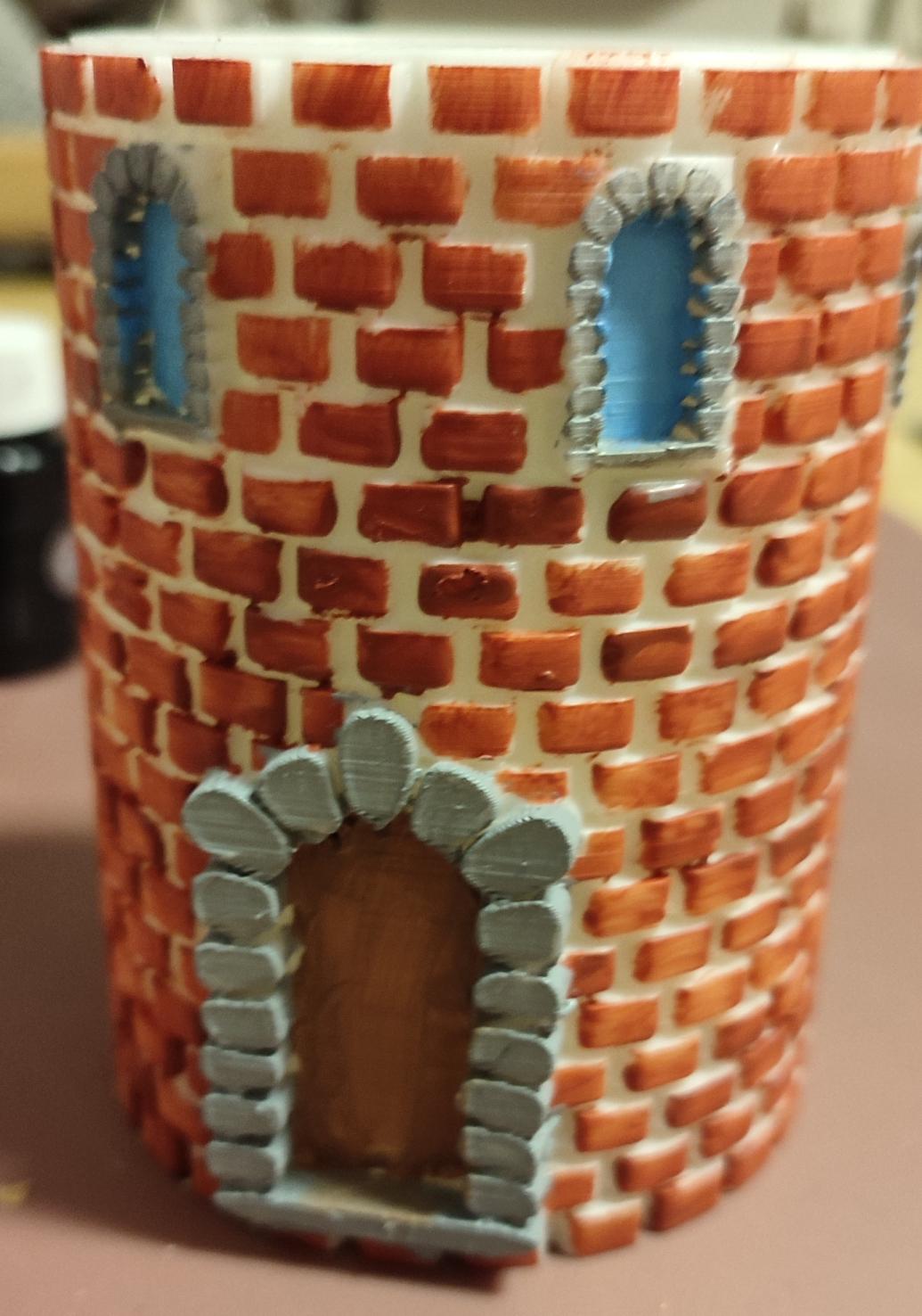





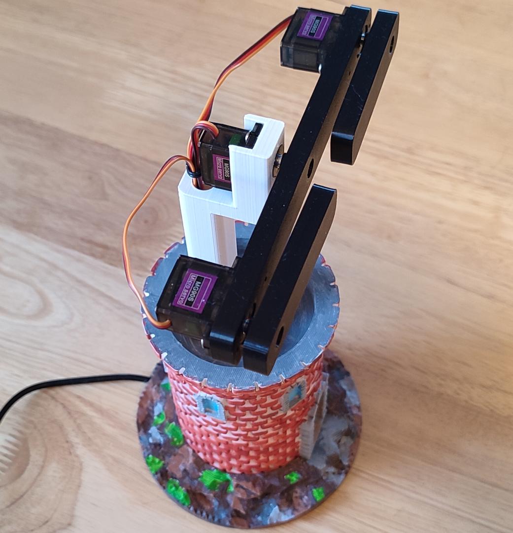

I started the construction with the painting of the tower, I wanted a more realistic look of the model. I took some pictures during the operation, and with the final result, I hope you like how it worked out. I have to warn you that it was the very first time I painted 3D printed models so I hope you don't judge me too harshly :)
While the painted parts were drying, I started to make the moving part of the project.
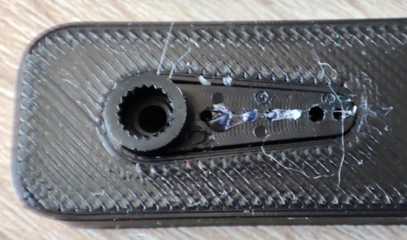
First of all, I fixed the actuator horns in the appropriate places. For the crossbar I used a double horn and for the arms, a simple horn. I glued the arms in place with a drop of hot glue (you have photos above).
I mounted the three actuators, one on the pole and on the crossbar the two actuators for operating the arms. I pressed the crossbar on the axis of the actuator then I pressed the 2 arms on the axis of the actuators. We did not fix with the corresponding screws neither the crossbar nor the arms because it is necessary to align them so that the movements are at the angles of 0, 45, 90, 135 respectively 0, 90 and 180 degrees. For this purpose I used the codes below (the first for the arms and the second for the crossbar) which I loaded into an Arduino Nano on a breadboard and of course, I connected in turn the servomotors that operate the arms (and the crossbar) to the Arduino module.
code for arms
#include <Servo.h>
Servo myservo;  // create servo object to control a servo
int pos = 0;    // variable to store the servo position
int min = 480;  //microsecond value for 0 degree
int max = 2500; //microsecond value for 180 degree

void setup() {
  myservo.attach(3, min, max); // attaches the servo on pin 3 to the servo object
}

void loop() {
 for (pos = 0; pos <= 90; pos += 1) { // goes from 0 degrees to 90 degrees
    // in steps of 1 degree
    myservo.write(pos);              // tell servo to go to position in variable 'pos'
    delay(15);                       // waits 15 ms for the servo to reach the position
  }
  delay(1500);
  for (pos = 90; pos <= 180; pos += 1) { // goes from 90 degrees to 180 degrees
    myservo.write(pos);              // tell servo to go to position in variable 'pos'
    delay(15);                       // waits 15 ms for the servo to reach the position
  }
  delay(1500);
  for (pos = 180; pos >= 0; pos -= 1) { // goes from 180 degrees to 90 degrees
    myservo.write(pos);              // tell servo to go to position in variable 'pos'
    delay(15);                       // waits 15 ms for the servo to reach the position
  }
  delay(4000);
}
code for crossbar
#include <Servo.h>
Servo myservo;  // create servo object to control a servo
int pos = 0;    // variable to store the servo position
int min = 520;  //microsecond value for 0 degree
int max = 2520; //microsecond value for 0 degree
void setup() {
  myservo.attach(3, min, max); // attaches the servo on pin 9 to the servo object
}

void loop() {
 for (pos = 0; pos <= 45; pos += 1) { // goes from 0 degrees to 45 degrees
    // in steps of 1 degree
    myservo.write(pos);              // tell servo to go to position in variable 'pos'
    delay(15);                       // waits 15 ms for the servo to reach the position
  }
  delay(1500);
  for (pos = 45; pos <= 90; pos += 1) { // goes from 45 degrees to 90 degrees
    myservo.write(pos);              // tell servo to go to position in variable 'pos'
    delay(15);                       // waits 15 ms for the servo to reach the position
  }
  delay(1500);
    for (pos = 90; pos <= 135; pos += 1) { // goes from 90 degrees to 135 degrees
    myservo.write(pos);              // tell servo to go to position in variable 'pos'
    delay(15);                       // waits 15 ms for the servo to reach the position
  }
  delay(1500);
    for (pos = 135; pos >= 0; pos -= 1) { // goes from 135 degrees to 0 degrees
    myservo.write(pos);              // tell servo to go to position in variable 'pos'
    delay(15);                       // waits 15 ms for the servo to reach the position
  }
  delay(3000);
}
At the first run of the code I noticed the successive positions, I stopped the movement (I turned off the power) of the servomotor in the 90 degree position and I took out the arm and I positioned it again as close as possible to the desired position. In the code you can fine-tune the movement of the servomotor by changing the values "min" and "max". If we do not define these values, the servo library sets them as follows: min = 544 and max = 2400 (I do not want to go into details but the two values are the PWM corresponding to the angles of 0 and 180 degrees - more on this at servo library page or in this blog post). These values are considered typical but the servomotors are very different, made by different manufacturers, so some adjustments are needed. I changed the values in 10 to 10 steps carefully, so as not to force the servomotor at the ends of the movement (a mechanical noise is heard when the servomotor wants to rotate too much) otherwise the servomotor may fail. When I was satisfied with the result, I wrote down these values (I used them in the final code) Below there is an animated gif with the movements of the servomotor after adjustments

I did the same on the other servomotor on the arm. Now I could fix the arms with screws.
I aligned the crossbar in the same way at 0 degrees and fixed the bar to the servomotor shaft with a screw. You can see the result in the animated gif below.

Then I passed the wires of the actuators through the hole in the column and after the paint dried on the tower cover, I also passed the wires through the hole in the cover and I fastened the pole to the cover with four screws and nuts.
I then made the connections according to the electronic scheme, loaded the program into the Arduino Nano module and put the cover on the tower (I fixed it in its place with a drop of hot glue for safety).
Software
The program to be uploaded to the Arduino Nano can be found on GitHub here.
It is not something extraordinary, the code is relatively simple and easy to follow and is therefore easy to further develop based on it.
It consists of 2 parts:
- Communication part of the HC-06 Bluetooth mode with a serial terminal installed for example on an Android phone
- The actual display part of the message sent from the phone (movement of the actuators in the desired positions)
The first part is simple. When the Bluetooth connection is active and the buffer contains characters to be sent from the phone to the Arduino Nano module, a string variable is initialized with these characters, each character is transformed into caps and the white characters at the beginning and end of the transmitted string are removed. Then each character in the string is checked one by one and "displayed".
The second part is not particularly complicated either, but here I had a small problem at the beginning: the “SoftwareSerial” library conflicts with the “Servo” library. This conflict is manifested by some short and sudden movements of the actuators during data transmission over Bluetooth (especially from the Arduino module to the phone) and it is very annoying. I searched the internet and saw that many others have this problem with these two libraries. Mainly two solutions have been suggested: the use of another library for servomotors or the alternative use of libraries, ie the deactivation of one when using the other. I used the last solution: I activated the use of servomotors only when I really needed their movement. You can see this in the source code.
Some remarks.
I separated in a few stages the display of a message but also of a character.
Thus at the start of the device (but also at the end of a message) the crossbar will rotate in the horizontal position, 90 degrees, and the 2 arms in the middle position, ie 90 degrees. In the alphabet table this state corresponds to the number 7. Also when starting the device and initializing the three servo objects the motors rotate in these positions so the choice was logical. If this state lasts more than 4 seconds it means that it is the end of message (either the beginning of a message). Next, as I said before, after receiving the string of the message via Bluetooth, each character from the received string is checked one by one. First the crossbar is rotated, then the upper arm and then the lower arm. The device remains in one position for 3 seconds after which the next character is displayed in the same way. At the end of the message, the crossbar is rotated in horizontal position, and the arms in the position corresponding to the angle of 90 degrees and remain so, even if it is already a message sent in the buffer, for 5 seconds.
I commented as much as possible on the source code so that it is easy to follow, I hope there isn't any problem with understanding it.
The application for sending messages to the Arduino module is called "Serial Bluetooth Terminal".
To send a message, all you have to do is install this application, turn on the optical tower, activate bluetooth on your phone and after scanning the surrounding bluetooth devices, connect to the HC-06 module. On my phone it appeared as a "unnamed" and the password was 1234. The application is started, the bluetooth device to which you will connect is chosen and next the message is sent. That's all!
Starting the Communication :)
In the video below you can see the Optical Telegraph Model in action.
In the first part I transmitted a short message, the project title, in the second part I wanted to show how each letter and each number look like at the time of the transmission, and in the last part I "displayed" the message sent by Claude Chappe at the first official presentation of the optical telegraph on March 2, 1791.
“Si vous reussissez, vous serez bientot couvert de gloire”
(If you succeed, you will soon bask in glory).
A premiere after 230 years! :)
The background music in this video was generated using Mubert Render.
Some Conclusions
The realization of this project was very fun. And it wasn't hard at all.
The software part gave me a little work but in the end everything was solved.
I invite you to try to make this model, you can edit and change the 3D printed components as you wish and the software I am sure can be much improved.
I think that it is a very suitable project for children, who can learn many things during its construction.
As always, I am waiting for your questions and comments.