3D Printed Print-in-Place Sea Scooter: Wireless and Waterproof With Whopping Widgets
by designedtomake in Outside > Water
1468 Views, 16 Favorites, 0 Comments
3D Printed Print-in-Place Sea Scooter: Wireless and Waterproof With Whopping Widgets

)
Around nine months ago, on a particularly drizzly day, I had a wild idea: what if I could 3D print in place my very own sea scooter in time for the summer? I wanted to challenge myself with two key design constraints you won't see anywhere else: the entire hull must be a single, one-piece print, encapsulating all the electronics and a battery. And, crucially, the hull must be hermetically sealed, with no holes for drive shafts or electrical connections. This project would take me 500 hours of design, building, and testing.
Supplies
- 3D printer capable of large-scale, long-duration prints. 280mmx280mmx270mm build volume at least.
- Filament (ASA, PLA, Nylon and Polycarbonate)
- Epoxy resin
- 8 x LiFePO₄ battery cells 26650 size
- 8S Battery Management System (BMS)
- 775 Motor and 15 A motor controller
- 15 A relay switch
- a raspberry Pi Pico for the brain of the sea scooter
- For the Magnetic gear:
- 8 x 30mm x 5mm x 10 mm bar magnets
- 20 mm diametrically magnetised magnet
- 5 rectangular iron pins 30mm x 5mm x 3mm iron
- some 1mm sheet steel
- Wireless charging coil and electronics
- Reed switch and Hall sensor for wireless control
- Various small components (screws, bearings, wires, electrical connectors, etc.)
- some good CAD software.
The "Impossible" Design Challenge
I started this project with two seemingly impossible design constraints to make it interesting:
- The body of the sea scooter had to be a single, fully enclosed 3D print. This "print-in-place" method meant I had to figure out how to add all the internal components during the printing process itself.
- The body had to be waterproof and hermetically sealed, with no holes for a motor shaft, wires, or connectors. This meant I needed a way to get power and control signals into and out of a system that has no physical connection to its outside environment.
These two challenges guided every design decision I made.
Making a 3D Print Watertight
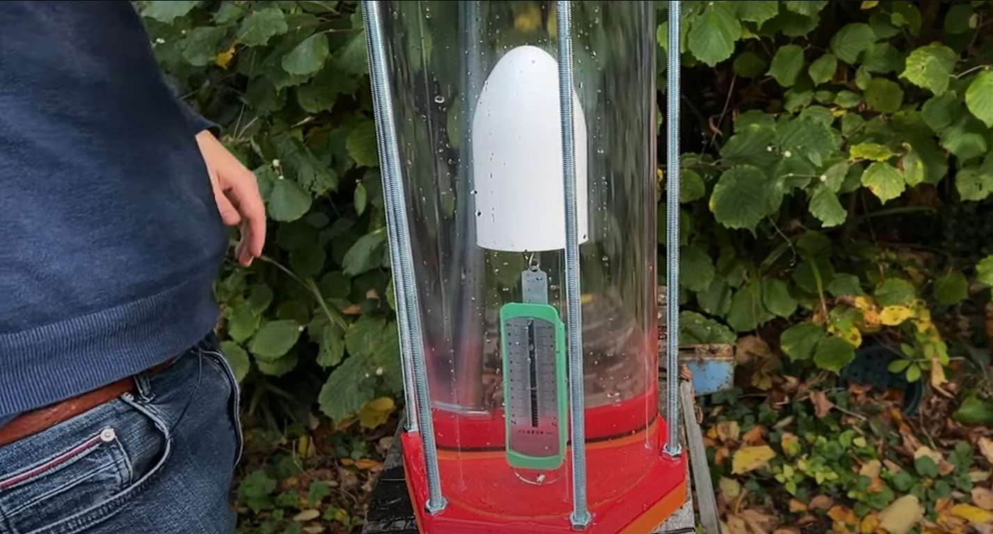
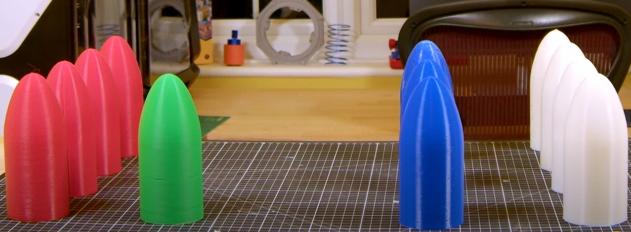
Before I could build the sea scooter, I had to answer the most fundamental question: can a 3D print be truly waterproof? I designed a pressure-testing rig to simulate underwater conditions, testing various filaments and post-processing techniques. While many methods failed, my experiments proved that a simple epoxy coating was able to stand up to significant water pressure. This was a critical first step, as it confirmed the project was even possible.
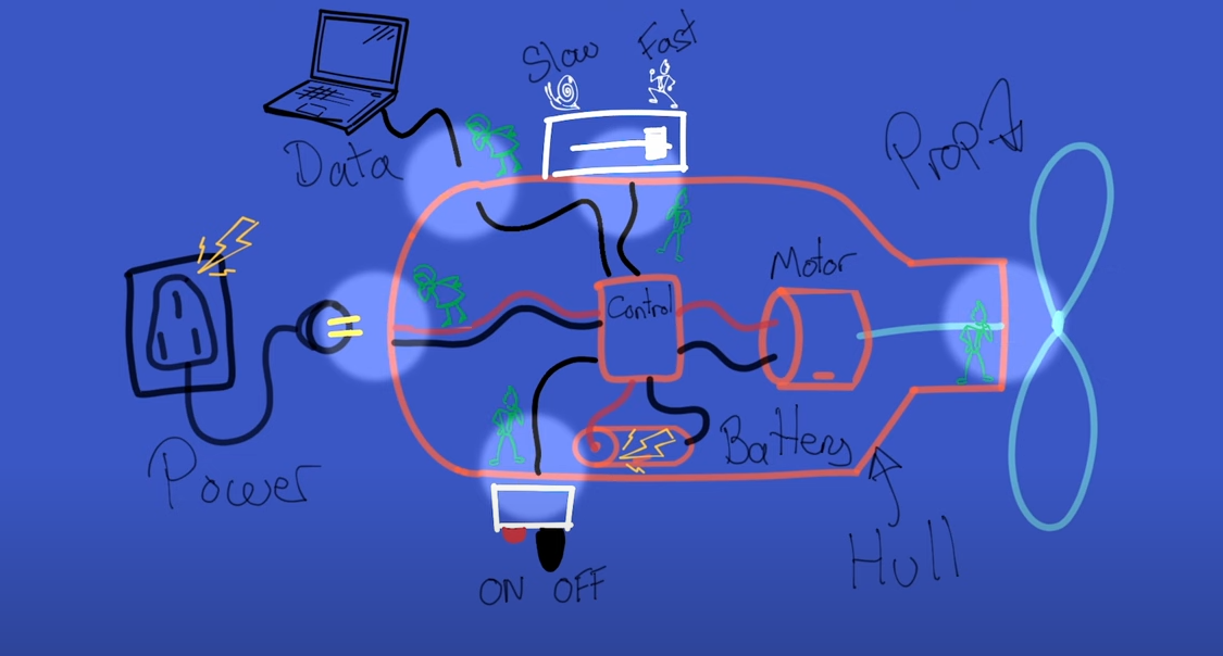
Designing an Underwater Wireless Control System

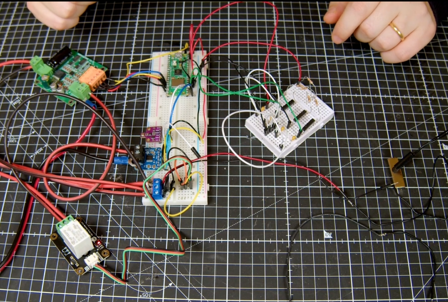
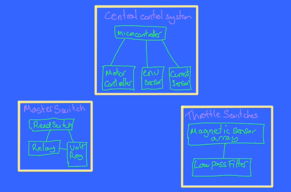
I knew that traditional wireless technologies like WiFi and Bluetooth would not work underwater, as water absorbs their high-frequency signals almost immediately. My solution was to use the power of magnetism. I designed a control system that uses a combination of a simple reed switch and a more sensitive Hall sensor to detect a magnetic field from outside the hull. This provides a non-contact, robust way to get control signals into the sealed hull.
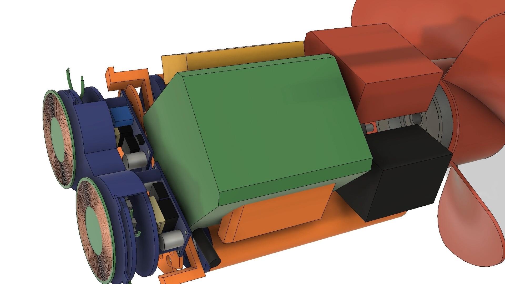
Building a Non-Contact Magnetic Drive System
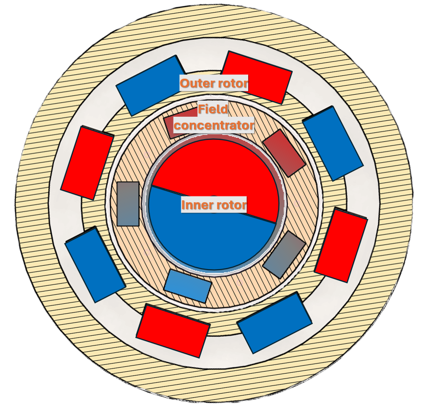
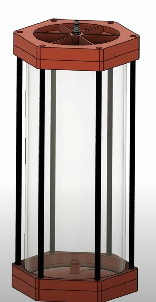
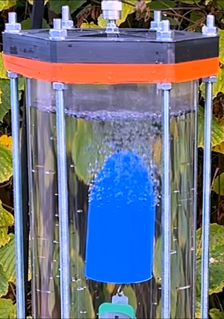
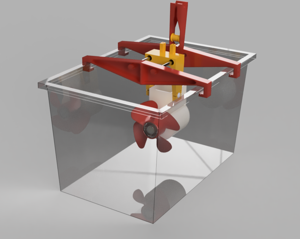
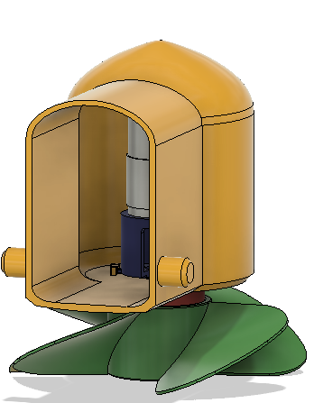
To solve the hermetic sealing problem for the propeller, I designed a non-contact magnetic gear. This assembly uses two sets of magnets to transfer torque through the plastic hull itself, eliminating the need for a physical shaft penetration. The internal magnetic rotor, driven by the motor, transfers 'magnetism' though the iron 'magnetic conductors' that are embedded into the hull's wall. This then causes the outer magnetic gear to turn, somewhat counterintuitively in the opposite direction and at a slower speed. my design gave a 4:1 reduction gearing. I also created a test hull to test the max thrust that this gear could transfer using an in bath testing rig with a range of propellers.
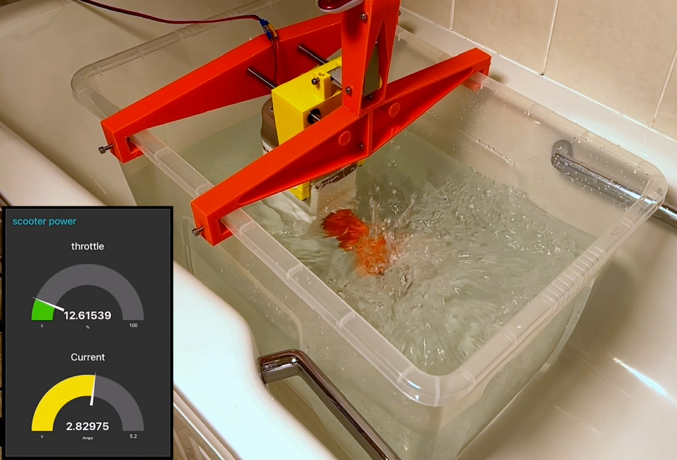
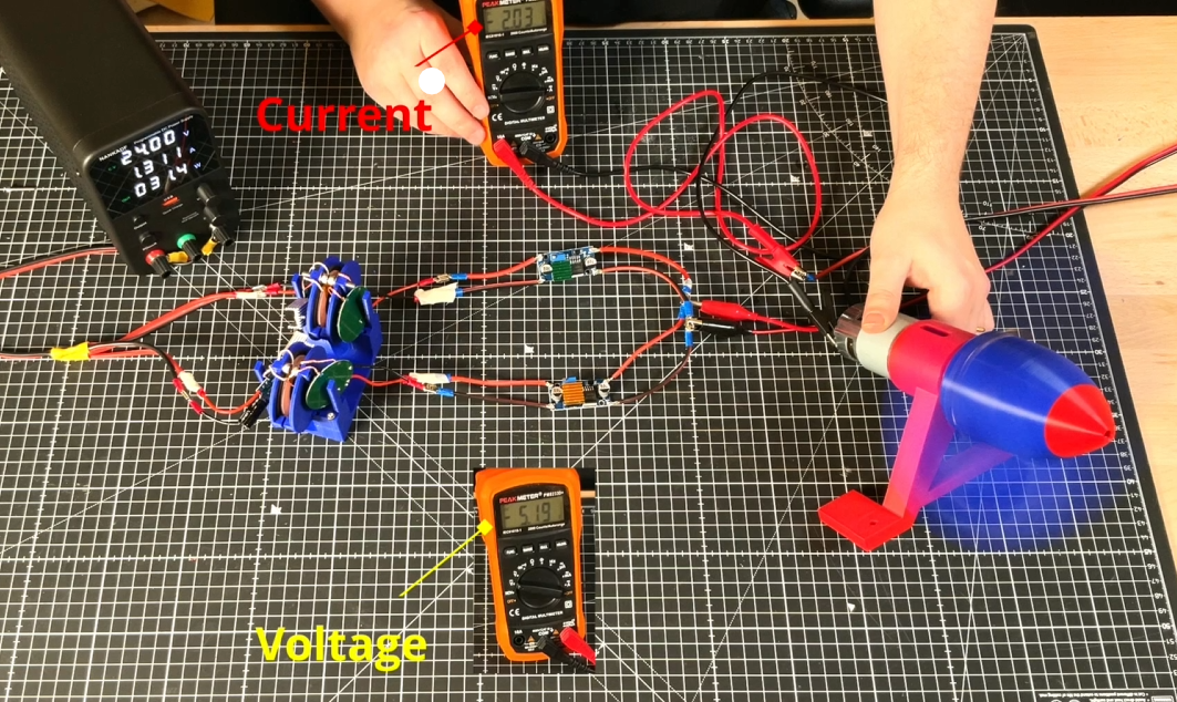
Testing the Drive and Control Systems
.jpg)

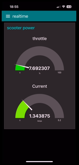
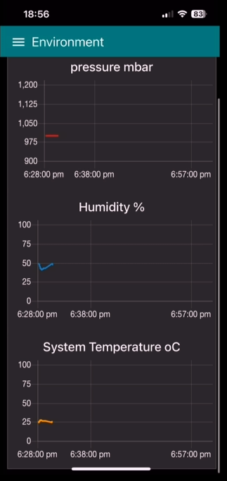
With the magnetic gear and wireless control systems designed and tested it was time to test it all in a controlled environment. to do this I created a bathtub test rig that would enable both the thrust (using some luggage scales) that the magnetic gear could provide with a variety of propellers and the operation of the wireless control systems in a realistic environmental setting. To record the s system state and environmental monitoring sensors built into the sea scooter I built a wireless IOT data collection gateway using HiveMQ to collect messages and NodeRed to read these messages and display them on a real time dashboard that I could access from my Phone during the testing.
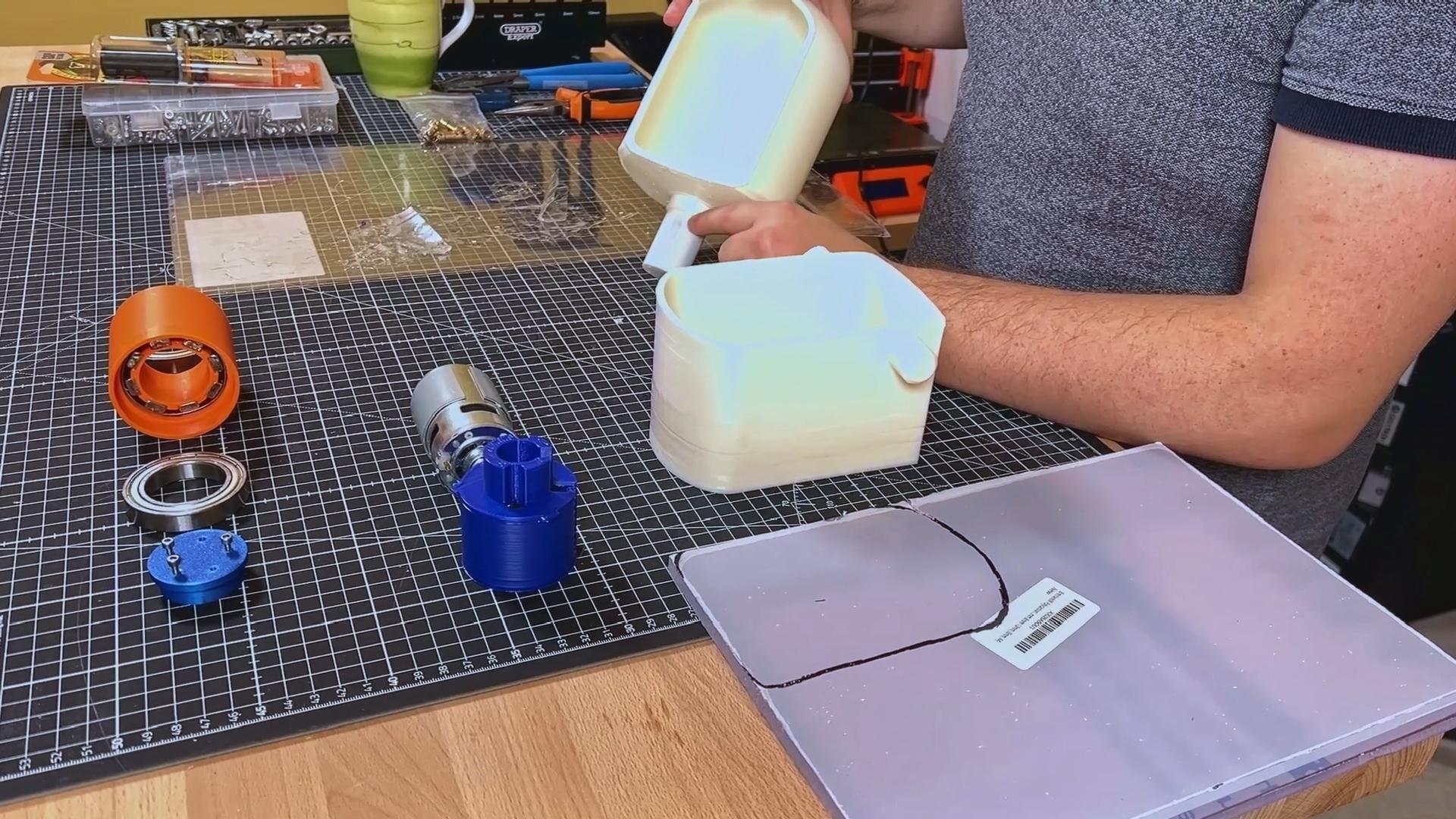
Powering the Sealed Scooter

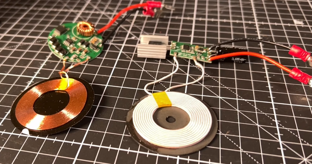
Since the scooter has no holes for a charging cable, I had to design a wireless power and battery system. I built my own custom battery pack using eight LiFePO4 cells, which gave me a 24-volt (26 V in reality), 2.5 Ah pack that fit snugly inside the hull. I then designed a wireless charging system that could get power through the hermetically sealed hull, which was a mini-project in its own right.
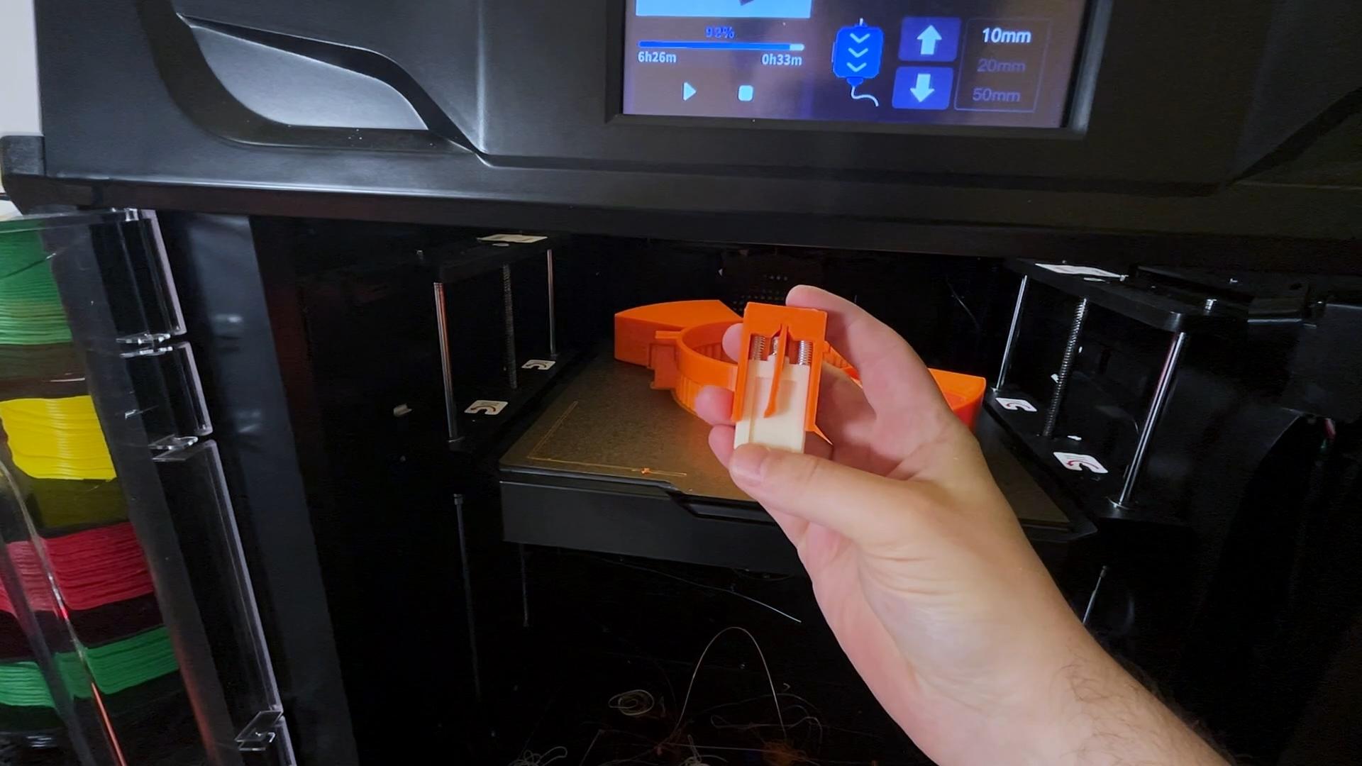
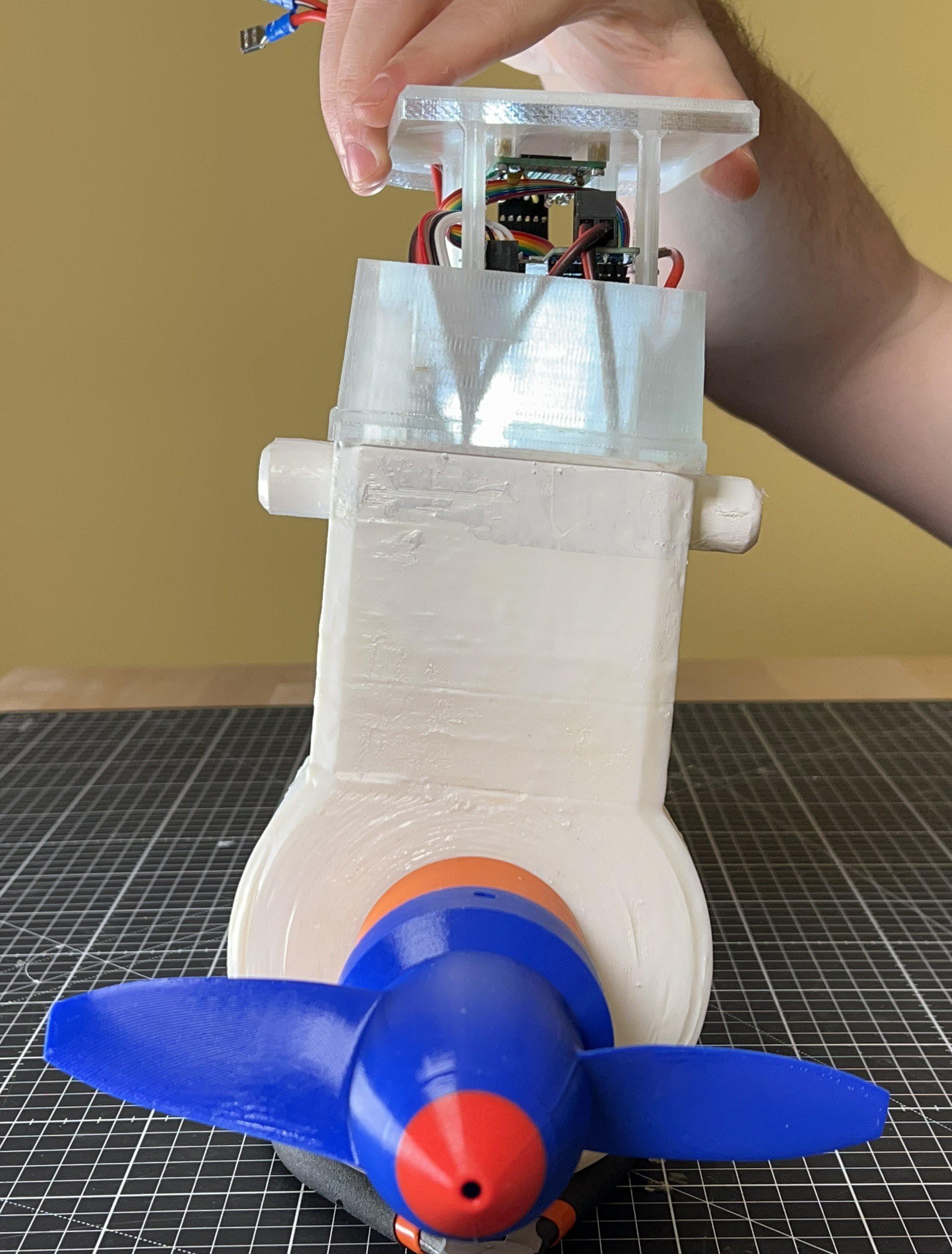
The Print-in-Place Process: a High-Stakes Assembly

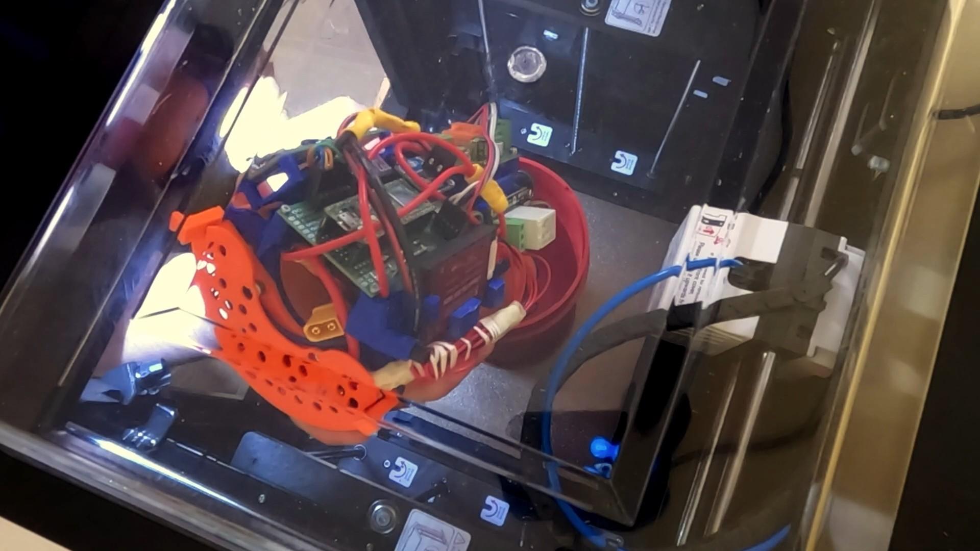
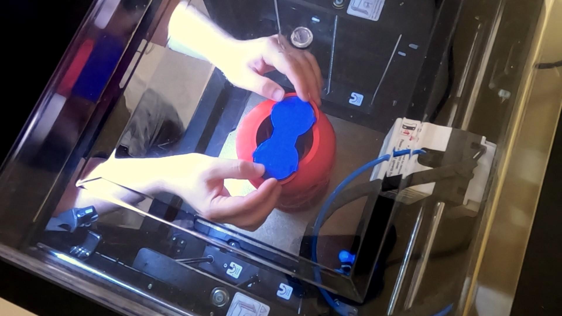
The final print was a nerve-wracking, 14-hour affair. The plan was to pause the print at specific layers to insert the internal "super widgets"—the magnetic gear, drive system and wireless charging coils—and then resume printing. A single mistake could have ruined the entire build.
- Insert the Magnetic Gear's Concentrator: My first pause was to embed the iron bars that form the field concentrator layer of the magnetic gear.
- Insert the Drive System: The next pause was for the largest component: the complete drive system. I had to manually adjust the Z-offset by 0.3mm to prevent the nozzle from hitting the newly inserted part and causing a print failure.
- Add the Wireless Charging Coils: The final pause was for the wireless charging assembly, which I connected to the battery and tacked in place.
Final Assembly and Testing
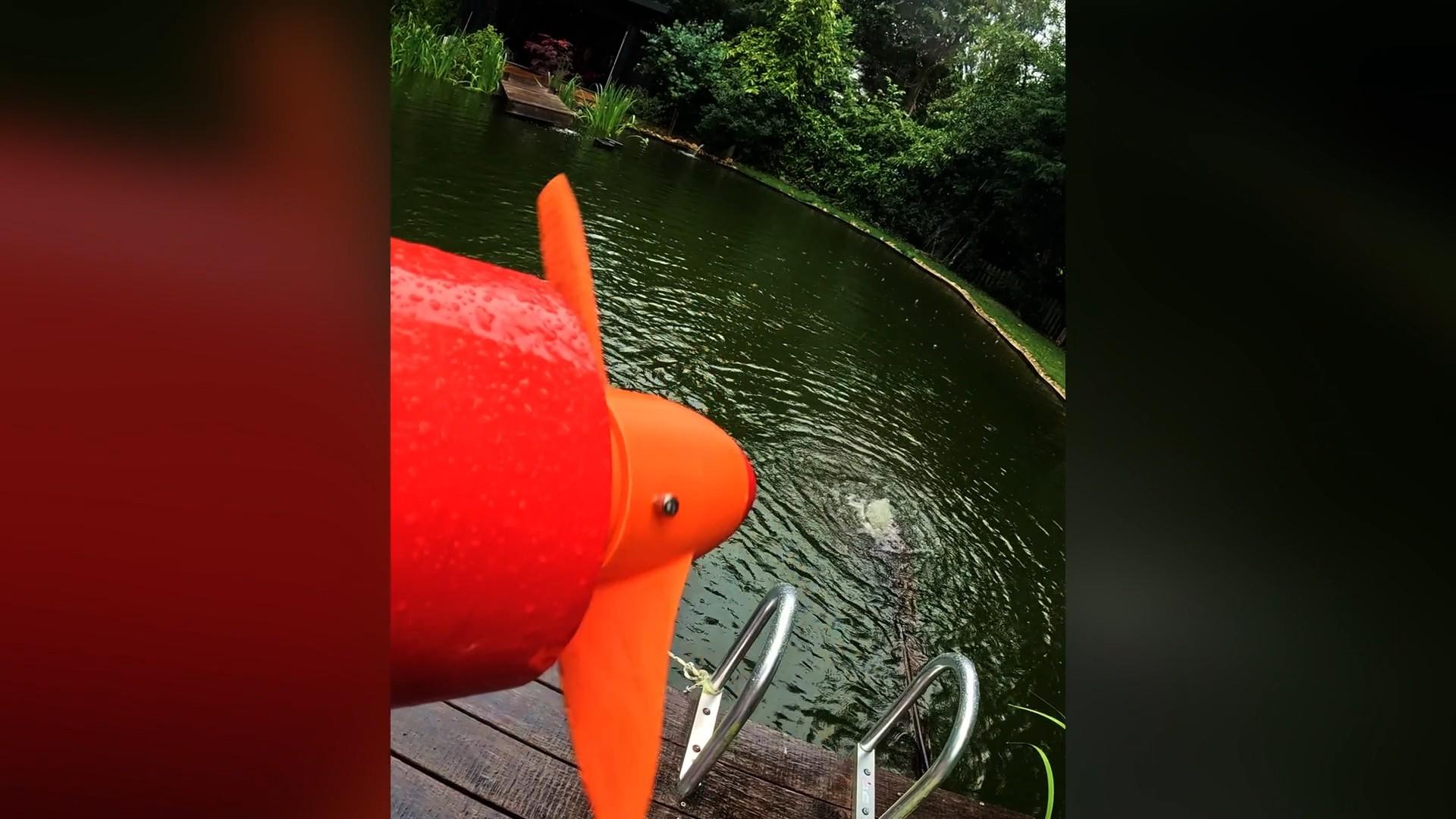
After the print finished successfully, I had a completed hull with all the internal systems encapsulated. My last step was to coat the exterior in epoxy, making the hull as watertight as a real submarine.
To see the final assembly process and the sea scooter in action, you can watch the full build and maiden voyage on the YouTube video linked below!
What I Learned
)
This project was a massive challenge that pushed the boundaries of what is possible with consumer-grade 3D printing. I learned that with clever design and a little bit of daring, you can overcome seemingly impossible engineering constraints. I hope this project inspires you to tackle your own "impossible" builds and see them through to a successful conclusion.