3D Printed Rotating Display
by vincentpaulines in Workshop > 3D Printing
874 Views, 6 Favorites, 0 Comments
3D Printed Rotating Display


Hello hello! This is a small project I decided to work on since I have a few small figures and plushes that would be fun to have rotate around (especially the bobble head). From a few other rotating displays I have seen online, most of them use an internal gear mechanism to work. However, I decided to use bevel gears as I wanted to experiment more with 3D printing bevel gears and more importantly having a top platform with gear teeth showing would be cool looking. Here are the basic supplies needed to make this project:
Downloads
Supplies
Components:
- A small motor
- Battery Pack and 4 AA batteries
- 3mm Ball Bearings
- 2 Bearings
- Superglue
- 2mm and 3mm Screws
Tools:
- 3D printer
- Basic Soldering kit
Circuitry

For the circuitry, there is only the motor and battery pack so this is a simple task of soldering the two together. Though I suggest soldering the battery pack wires at a 90 degree angle to the motor as there is not a lot of space for the wires. I initially just soldered the wires parallel to the motor which resulted in the small motor connections breaking off. Furthermore, a switch is not required for this project as the battery pack used already has a switch.
Mechanical Design
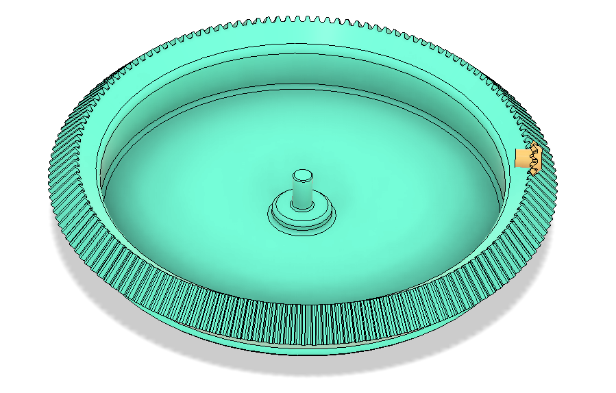
For the mechanical design it is only just the bevel gears. I wanted the top platform to rotate slowly so I decided on a very high gear ratio of 16:1 with the drive gear having 9 teeth and the driven gear having 144 teeth. For modeling the bevel gears, this is typically a tedious process if one tries to do an mathematically exact bevel gear. Though for a project like this, an approximated model is suffice (This is a good video on how to do this). Finally, as the driven gear also acts as the top platform, an axle was added to the center.
Design of the Base


For the base, I simply added little sections where the battery pack and motor can placed on along with covers that can be screwed on to the components. Additionally, a hole was added to the bottom where the battery pack switch can be accessed. One funny quirk of the design is that to save space, the cover for the battery pack doubles as the center of the display where the bearings and top platform axle go.
Moreover, when I printed the base, I realized that the motor was way too low for the bevel gears to mesh. Thus, I had to print a 2.3 mm block to aid the motor at the cost of the motor cover being screwed on funny (This mistake is fixed in the STL files I provide later).
Finally as the weight of the top platform is only supported at its center and at the driven gear, the bevel gear is subject to tipping. To answer this, I designed structural supports which can be superglued at unsupported areas (I only needed four). These are rods with ball bearings that can be attached on top which can roll with the movement of the bevel gear.
Finished!
Assembly is extremely simple as the motor and battery are to be screwed down (2mm and 3mm screws respectively) and the top platform is placed on top. Though not necessary, using tape to secure the wires to prevent them from popping out. After this, turn the switch on and voila!
This was one of the more fun short projects to do personally with how much time I can just spend watching dumb stuff spin around. STL files are down below if you'd like to replicate this.