3D TWISTER

Welcome to the creation of 3D Twister! We hope you enjoy learning about our process and maybe you can make this yourself!
Collaborators: Quentin Wingard, Kade Eisen, and Ashley Paulson
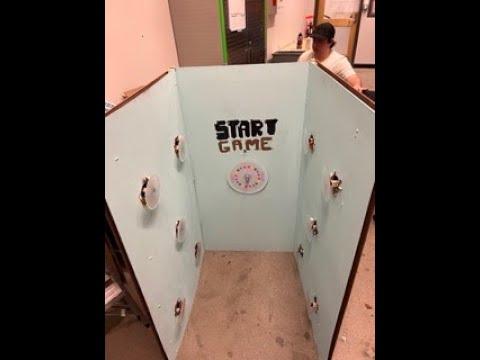
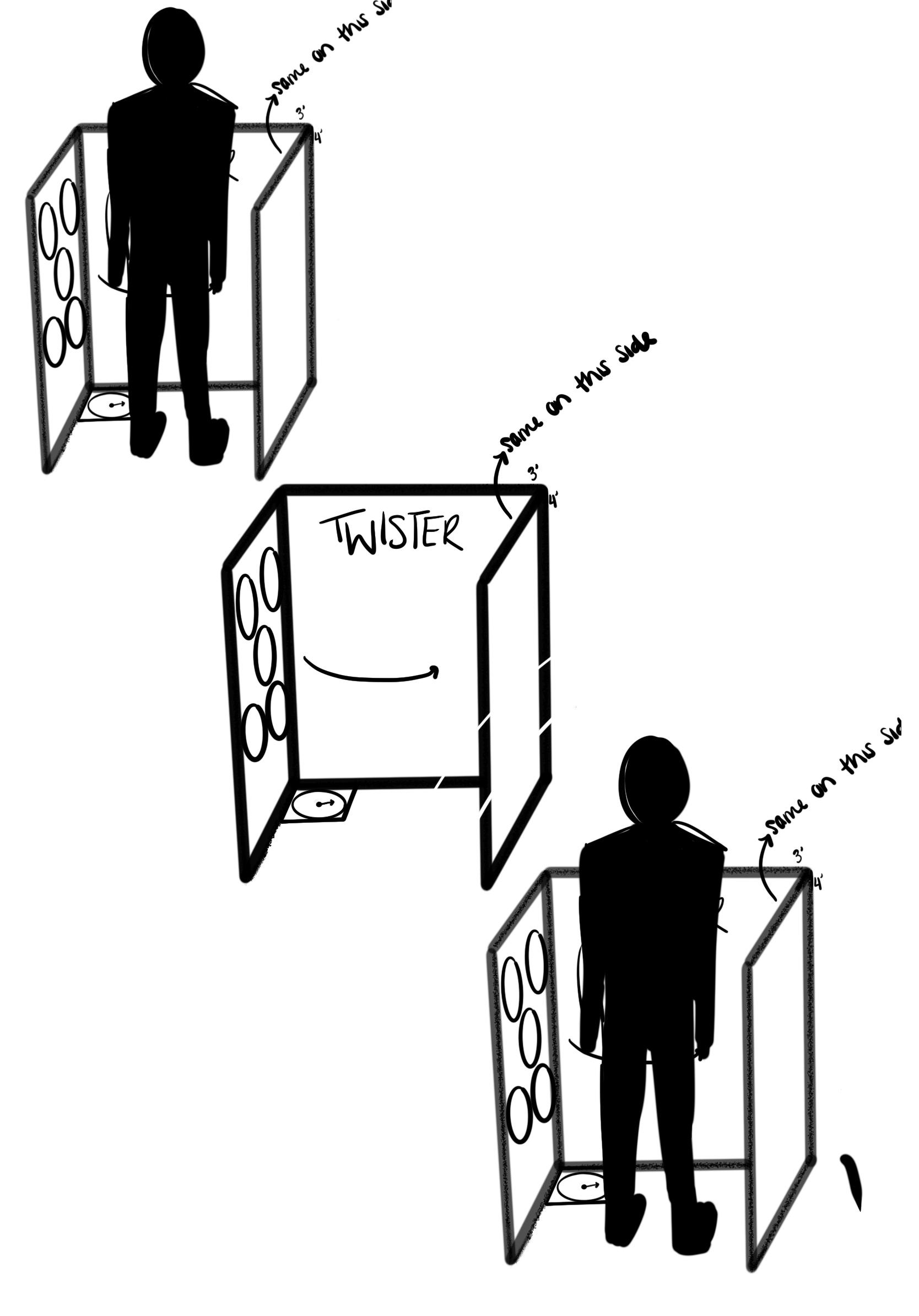
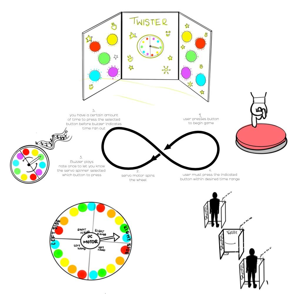
When brainstorming for this project our team quickly decided on creating an interactive game. The concept of a 3D twister stood out to us. We decided on inventing a unique version of the well-known game in which you stand inside a 3 sided box and use your hands and feet to press buttons on your left and right that will be lit up by LEDs underneath. Right away we ordered materials to begin the construction because we knew it would be time-consuming to build as large of a box as we wanted. We originally wanted to build a box that was 6 feet tall so that an adult could play the game comfortably, but we decided that, for ease of transport and wiring, we would downsize it to 4 feet tall and about 3 feet in width. During construction, we used the table saw in the ITLL to cut the boards to the correct size and then used nails, screws, and drills to put it together, then proceeded to use a drill attachment to put 5 holes on each side. During this time we each were working on separate parts of the code, programming a DC motor as our spinner that would have it spin anywhere from 1 - 5 seconds and land on a random marker on the spinner graphic to indicate which hand or foot to use.
As well as the LED code to have any one of the 10 buttons light up when the spinner is finished spinning, and finally, a buzzer connected to a button that starts 10 rounds of a 3-second countdown that indicates how long you have to successfully push the button. Finishing the code meant we had to finalize the construction and appearance of the project which involved laser cutting, gluing, and finishing each button and then attaching it inside each of the holes so that it is a satisfying button to push. We accomplished this by gluing a small portion of a dowel onto the back side of the box, which we had double-sided at this point with more of the hardboard, and gluing the button to the dowel. Each button was placed above 3 LEDs that we had purchased and soldered together. The soldering was a whole separate endeavor as we had allocated 3 LEDs to light up one button. Each LED had a ground, power, and pin connector. Three LEDs were to be placed behind the button, they (with those three wires each) were connected using a protoboard, and all 10 power lines and 10 Ground lines were soldered onto another proto board connecting 90 wires in total for just the LEDs. We connected the third wire of each button to pins on the Arduino-Uno, which we had attached to the back of the box. The button was connected to the buzzer through soldering as well and tested to make sure that the button triggered the tune we programmed, the spinner was tested and secured to the board, half inside the enclosed circuit space and half outside so that it was visible above the spinner artwork that was placed on the game. Each of the individual parts worked properly except that when we combined them and tried to test the full project, we could not due to a short, which after sorting through the wiring we located the cause of the short. One of the LED wires had caused a short. When we connected it to the Arduino, when everything else worked properly, it would turn the Arduino-Uno off. So we decided to show what we had, our polished and finished project, and show it to our instructors, and then after the demonstration day, take it apart to test and document each of the working parts again. Using those clips in the video, we described how the project went wrong and what we would have done differently in the future. Wiring was our issue. We should have coordinated each of the LED wires better, color coordination would have helped. A suggestion from our instructor was to line the wires along the inside of the box vertically and horizontally to keep everything more organized and to help with visibility.
To Sum up our experience, we each enjoyed flexing new muscles and developing new skills when it came to organizing this project, thinking critically, exploring electronics, soldering, problem-solving, and more. Our team collaborated well on this project and gained more knowledge in circuits. We all were eager to learn and help one another, we tried our best and we all enjoyed this experience.
Supplies
Acquiring All Materials
For this part, go to your local home renovation store such as Home Depot and find all materials that can be found. As well, they can be found online on websites such as Amazon. Then make sure all materials are acquired and place them in an easy to find location.
Cutting the Boards

You will want to find a table saw and measure the correct distance at which you want the desired cut. We wanted 4X3' boards so we cut the length in half using the saw. Repeat this step until all boards are the same size.
Assembling the Boards

For this portion, you will want to connect the corners of 3 of the boards to make a U-shape. We used scrap pieces of wood to add support. To do so, we would line up the swap pieces of wood with the planks and nail them together. Then, we would face another plank to a different face of the scrap of wood and nail those together. After this was done for all 3 walls and it was shaped as a U, that part of the enclosure was done.
Cut and Size the Buttons and Spinner
With the laser cutter, cut an arrow for the spinner and buttons to the size of your preference. However, make sure that the arrow for the spinner is not too heavy for the motor when spun as this will cause issues with the spinning.
Cut Holes Into the Walls
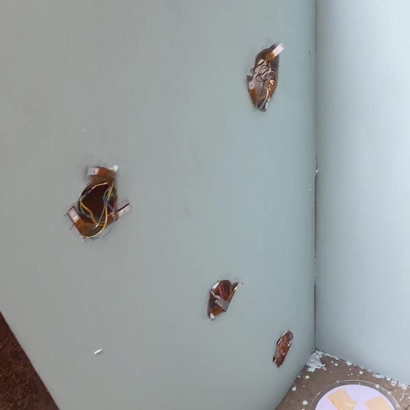
Now that we have the button sized as we like, cut holes into the walls that fit the buttons that will be attached to the back of the acrylic circles. Cut these holes on the side walls as the middle wall will be used to place the spinner and start button.
Make the Spinner

Now that the arrow is made, make a circle with alternating colors and write "Right Hand", "Left Hand", "Right Leg", and "Left Leg. After you will want to hot glue the back of the motor to the center of the spinner. After this is done, hot glue the acrylic arrow to the motor part that spins. Make sure none of the glue spills over as this can damage your motor.
LED

Cut the Neopixel strips into 30 individual strips as you will want to stick 3 of these individual strips evenly on the back of the acrylic circles.
Soldering

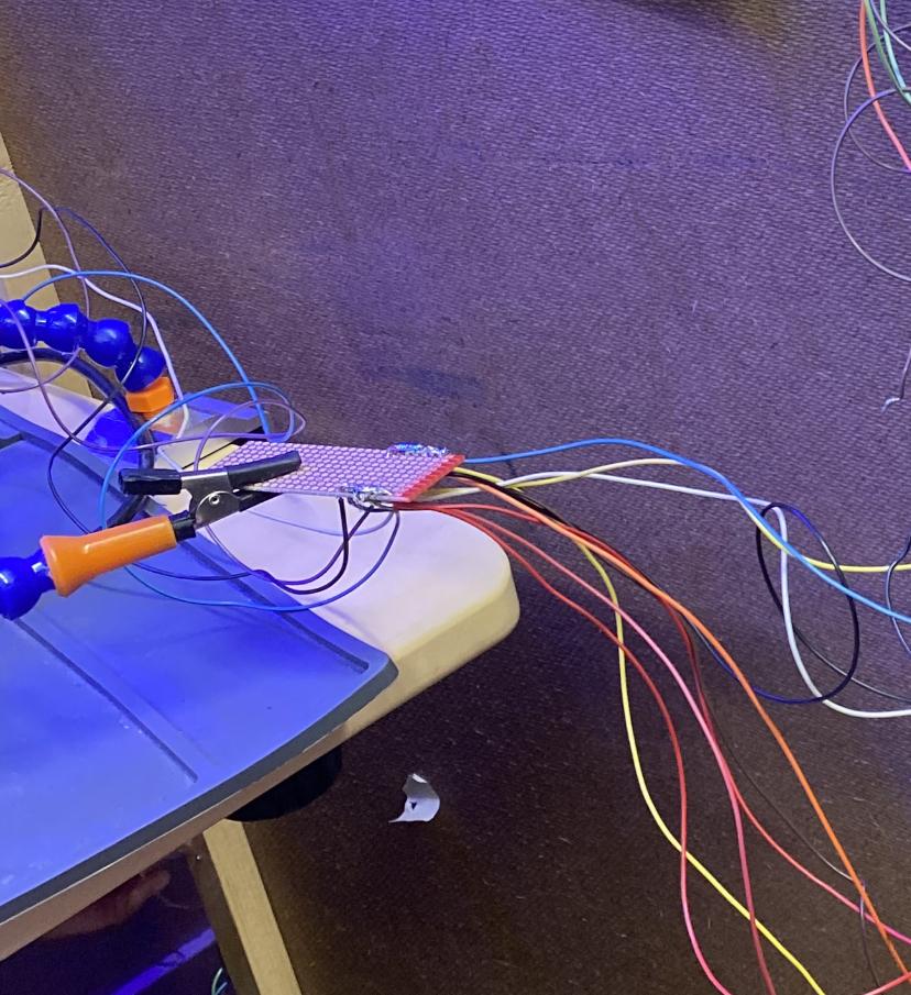
Once all buttons are set up solder the wiring to the LED's and to allow connections. Make sure to organize and color code your wires to not lose track. Test every individual button once they are done as well to make sure there is no shorting.
Downloads
Buzzer

Connect a buzzer to a protoboard and solder them together. As well, solder a button the wires connected to the protoboard to connect the button and buzzer.
Installation


Install all buttons, spinner, and start button into their respective holes and hot glue them in place. As well, when placing the wires, make right angles and organize them properly so that they don't get mixed up. As well, ensure there are no stray wires as it may cause a short.
Downloads
Enclosure


Add the back panels to all walls except for the wall that includes the Arduino board as you will need access to add the code and power supply. Use the screws and screwdriver to fasten these walls.
Downloads
Code
You will want to plug into your code the code found below to allow the Arduino board to function properly and to have all pieces work together:
Here is the link for the code to make the 3D Twister work: Link
Finish


Once everything is coded, drill a hole into your back panel that allows the power supply to come through. Screw in the back panel and pass the power supply through the hole and connect it to the Arduino. Enjoy and have fun with the game!