3D Zoetrope From Junk

This project began when one of the large LED lights on the workshop roof failed. The electrician replaced it and was going to throw it in the bin. I kept it, not really knowing if I could fix it, so it sat around for a few months until I pulled the driver apart and found it was full of resin and not repairable. I also had a 48volt battery charger kicking around from an old mobility scooter that has been chopped up for other projects. Turns out they play nice together, so now I have a massive LED lamp- what to do with it? With a few more components, I could make a 3D Zoetrope, get some art students making figurines, and have something with a bit of a WOW factor.
What is a 3D zoetrope?
A 3D zoetrope is like a tiny 3D movie that you can watch without a TV or computer.
It uses lots of small 3D models arranged in a circle. Each model is a slightly different step of an action.
So how does it work?
The important parts are:
The 3D figures are like individual frames in a movie. Each one shows the next part of the movement.
A motor spins the platform very quickly, bringing each figure past you one after another.
A normal zoetrope has slots or holes that you look through. They act a bit like a camera shutter, briefly blocking your view between each figure. This zoetrope uses a strobe lamp to achieve a similar effect.
Your brain is very good at connecting pictures that are shown one after another. Instead of seeing lots of separate figures, you see one figure moving.
Supplies


I used the following. Most of the parts and supplies I had were from old projects or stuff that was going to be thrown out.
Junked LED lamp
48v volt battery charger that works, but I had no use for it
Bottle caps: lots and lots of bottle caps!
Arduino
stepper motor
Stepper controller
MOSFET for switching the LED
Power supply for the stepper and Arduino
3d printed parts
Laser-cut disc
Steel frame
3D printed figurines or handmade figurines
Paint, wire, screws, etc
Getting the Lamp to Work


The first step went pretty smoothly: getting the lamp to work. The driver for the lamp was not repairable, and I tried a couple of laptop chargers, but the voltage was too low to light up the LEDs. I found a 48-volt battery charger kicking around from an old mobility scooter in my junk box, and it worked perfectly straight out of the box.
3D Printed Mounts


Next, I printed some 3D-printed parts to hold the stepper motor and the disc. The laser-cut disc was next, and those parts came together without a hitch. The stepper mount is designed to slide into 35mm SHS
Steel Frame


I designed and built a frame to hold the contraption together, and so far, so good. The frame is 35 mm x 2.5 mm thick, and the 3D-printed motor mount slides into the end of the steel. The hub slides onto the stepper motor, and the disc is held onto the hub with 3 mm screws
Using AI to Code the Arduino

I'm not very good at coding, so I used Perplexity AI to write code for the Arduino. It worked the first time; this is the prompt I used.
"I want to build a large 3D zoetrope with a stepper motor, Arduino, and a large LED lamp. I have 20 segments; the lamp would need to flash 20 times per rotation. The disc is 500mm in diameter. I would like to be able to change the speed of the stepper motor with a potentiometer. I have the driver set at 400 microsteps per revolution. The lamp needs to flash in synchronisation with the segments on the disc. Can you write the code for the Arduino?"
#include <AccelStepper.h>
const byte STEP_PIN = 2;
const byte DIR_PIN = 3;
const byte EN_PIN = 8;
const byte SSR_PIN = 9;
const byte POT_PIN = A0;
const long STEPS_PER_REV = 400; // your driver setting
const int SEGMENTS = 20;
const int STEPS_PER_SEGMENT = STEPS_PER_REV / SEGMENTS;
const float MIN_RPM = 1.0;
const float MAX_RPM = 120.0;
const unsigned int PULSE_US = 300; // lamp on-time pulse
const int POT_DEADBAND = 3;
AccelStepper stepper(AccelStepper::DRIVER, STEP_PIN, DIR_PIN);
long nextFlashStep = 0;
bool lampOn = false;
unsigned long lampOffTime = 0;
int lastPot = -1000;
void setup() {
pinMode(EN_PIN, OUTPUT);
pinMode(SSR_PIN, OUTPUT);
digitalWrite(EN_PIN, LOW); // enable driver (change if yours is active HIGH)
digitalWrite(SSR_PIN, LOW);
stepper.setMaxSpeed(3000);
stepper.setAcceleration(3000);
}
void loop() {
int pot = analogRead(POT_PIN);
if (abs(pot - lastPot) > POT_DEADBAND) {
lastPot = pot;
}
float rpm = MIN_RPM + (MAX_RPM - MIN_RPM) * (pot / 1023.0);
float stepsPerSecond = (rpm * STEPS_PER_REV) / 60.0;
stepper.setSpeed(stepsPerSecond);
stepper.runSpeed();
long pos = stepper.currentPosition();
if (pos >= nextFlashStep) {
digitalWrite(SSR_PIN, HIGH);
lampOn = true;
lampOffTime = micros() + PULSE_US;
nextFlashStep += STEPS_PER_SEGMENT;
}
if (lampOn && (long)(micros() - lampOffTime) >= 0) {
digitalWrite(SSR_PIN, LOW);
lampOn = false;
}
}
Downloads
AI Wiring Diagram Fail

AI did a great job with the code, making a silly graphic on step four and editing the title page, but creating the wiring diagram- sadly, this is the best it could do; it is pretty much unusable. The diagram has some information, but there are errors, so please don't follow it too closely; the project won't work.
Wiring the Mosfet


I had this MOSFET module in my junk box. I have no idea where it came from, but it works well. I also put a heat sink on the MOSFET, as it can overheat and burn out
- The VIN and GRD pins go to your power supply for the lamp; in my case, it is around 60 volts
- The V+ and V- pins go to the LED lamp
- VCC goes to a 5-volt pin on the Arduino
- The small GRD pin goes to ground on the Arduino
- The SIG pin goes to pin 9 on the Arduino
Wiring the Potentiometer
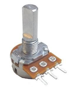
The potentiometer is there if you want to play around with the RPM. I found the zoetrope worked well at a high RPM. The drawings seem to work better at a lower RPM.
- The centre pin of the pot goes to A0 on the Arduino
- The left pin of the pot goes to the Arduino ground.
- The right pin of the pot connects to the Arduino 5V pin.
- You can reverse the direction of rpm change by reversing the ground and 5 volt pins
Wiring the Stepper Motor to the Driver

The stepper motor has four wires, and there are 2 sets of coils inside the motor. I just checked it with a multimeter to identify the two wires that go to one coil; then the other two wires will go to the other coil.
- One pair of stepper motor wires goes to A+ A-
- The other pair go to B+ and B-
- GND and VCC go to the stepper motor power supply. I used 12 volts
- DIR- connects to pin 8 on the Arduino
- DIR + connects to pin 3 on the Arduino.
- DIR + also connects to pin PUL+ on the stepper driver
- PUL- connects to pin 2 on the Arduino
Driver Setting

On the side of the driver, there are some DIP switches. The first 3 are to control the micro steps, and I chose 400 for this project, as it makes the stepper run smoothly at a reasonable speed without too much noise.
The combination is 1 on, 2 off, 3 on.
The next 3 switches control the current to the motor. I want the lowest current that the motor will run reliably to reduce the heat buildup.
The combination is 4 on, 5 on, 6 off.
That gives a current of 1.5 amps.
Bottle Cap Set Up


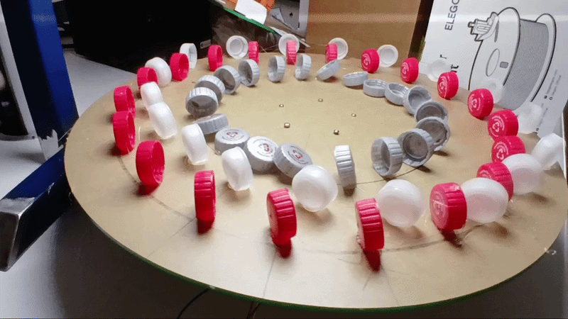
First, I had to climb into the garbage bin like a starving raccoon to find 60 bottle caps. I found setting up to be the most difficult and time-consuming. I found the easiest way to set up the animation is to position the 12 o'clock, 3 o'clock, 6 o'clock, and 9 o'clock bottle caps first, then work between each position. I found that if I started at one and worked from the start to the end, it became a mess pretty quickly.
Bottle Cap Test
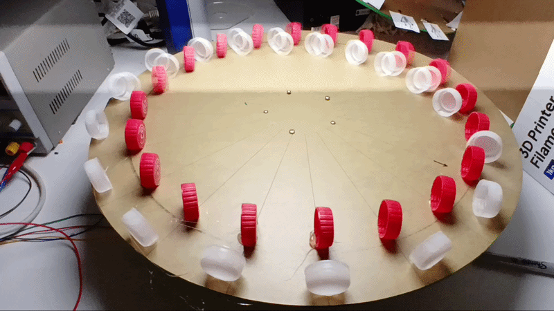
The GIFs show testing and progress on the project. You may have to click on the image to make the GIF work
The lines in the video are artefacts from the camera shutter getting out of sync with the strobe; it also gave me a headache trying to film this, so if you are sensitive to flashing lights, it may give you a migraine or worse.
I also had to turn the video into a GIF, which was a bit tricky. The video has to finish exactly on the 20th frame and repeat, or it will glitch and look a bit nuts
"Caps" Finished
.gif)
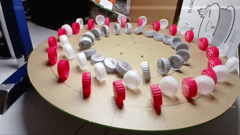
After much playing around with the set up I got a result that Im happy with, and the animation looks pretty good. The students quite like it and want to make their own version.
Lego Man Test
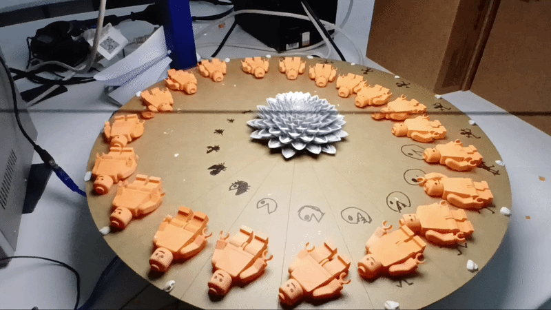
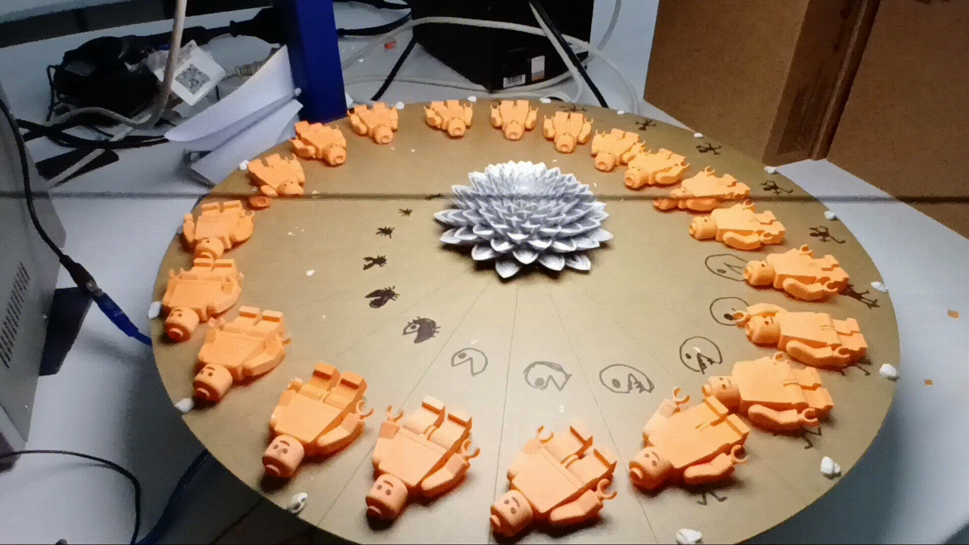
I 3D printed 20 Lego men and laid them on the disc with blue tack as a test run. I also drew a spider Pac-Man thing just to see what would happen. You might also notice the dot of blue tack running around the edge of the disc. Just by moving the object farther forward or backward on each segment, you can make it appear to run around the disc. I'm pretty happy with it, and some of the students were very interested in how it works and got a bit hypnotised looking at it.
The lines on the video are artefacts from the camera shutter getting out of sync with the strobe; it also gave me a headache trying to film this, so if you are sensitive to flashing lights, it may give you a migraine or worse.
Adding a Start Button With AI

Again, I prompted Perplexity AI with the Arduino code "I would like to add a start button that turns on the stepper motor and, 3 seconds later, turns on the LEDs. I want the zoetrope to run for 30 seconds, then turn off the LEDs, then, 3 seconds later, turn off the stepper motor. I also need the start button to be ignored until the zoetrope turns off, as children are likely to push the button repeatedly before the cycle is finished."
This is what it came up with, and it worked the first time.
DeviceArduino pinNotes
Stepper driver STEP D2
Stepper driver DIR D3
Stepper driver ENABLE D8
Assumes LOW = enabled; change constants if yours is opposite
MOSFET gate / LED trigger D9 Use through your gate-driver circuit
Start pushbutton D7 Other terminal goes to GND
Potentiometer wiperA0 Outer terminals to 5 V and GND
#include <AccelStepper.h>
// ---------------- Pin assignments ----------------
const byte STEP_PIN = 2;
const byte DIR_PIN = 3;
const byte ENABLE_PIN = 8;
const byte LED_PIN = 9;
const byte START_PIN = 7;
const byte POT_PIN = A0;
// ---------- Zoetrope / motor configuration ----------
const long STEPS_PER_REV = 400; // Driver setting: microsteps per full disc revolution
const byte SEGMENTS = 20;
const long STEPS_PER_SEGMENT = STEPS_PER_REV / SEGMENTS; // 400 / 20 = 20
const float MIN_RPM = 1.0;
const float MAX_RPM = 120.0;
// LED strobes for this time at every segment position.
// You have tested 50 us. Adjust only if needed.
const unsigned long PULSE_US = 50;
// ---------- Sequence timings ----------
const unsigned long LED_START_DELAY_MS = 3000; // Motor runs for 3 s first
const unsigned long LED_RUN_TIME_MS = 30000; // LEDs strobe for 30 s
const unsigned long MOTOR_STOP_DELAY_MS = 3000; // Motor runs 3 s after LEDs stop
// Change these if your hardware works the opposite way.
const byte DRIVER_ENABLED = LOW;
const byte DRIVER_DISABLED = HIGH;
const byte LED_ON = HIGH;
const byte LED_OFF = LOW;
// ---------- State machine ----------
enum RunState {
IDLE,
MOTOR_SPINUP,
LED_RUNNING,
MOTOR_COASTDOWN
};
RunState runState = IDLE;
unsigned long stateStartedAt = 0;
// ---------- Stepper / flashing ----------
AccelStepper stepper(AccelStepper::DRIVER, STEP_PIN, DIR_PIN);
long nextFlashStep = 0;
bool ledPulseActive = false;
unsigned long ledOffAtUs = 0;
// ---------- Button debounce ----------
bool lastRawButton = HIGH;
bool stableButton = HIGH;
unsigned long buttonChangedAt = 0;
const unsigned long DEBOUNCE_MS = 30;
bool startButtonPressed() {
bool raw = digitalRead(START_PIN);
if (raw != lastRawButton) {
lastRawButton = raw;
buttonChangedAt = millis();
}
if ((millis() - buttonChangedAt) >= DEBOUNCE_MS) {
if (raw != stableButton) {
stableButton = raw;
// Return true only on the debounced press transition.
if (stableButton == LOW) {
return true;
}
}
}
return false;
}
void setMotorSpeedFromPot() {
int potValue = analogRead(POT_PIN);
float rpm = MIN_RPM +
(MAX_RPM - MIN_RPM) * (potValue / 1023.0);
float stepsPerSecond = (rpm * STEPS_PER_REV) / 60.0;
stepper.setSpeed(stepsPerSecond);
}
void stopLED() {
digitalWrite(LED_PIN, LED_OFF);
ledPulseActive = false;
}
void startCycle() {
// Enable the stepper and start its 3-second spin-up period.
digitalWrite(ENABLE_PIN, DRIVER_ENABLED);
// Reset position and flash reference so the cycle always begins predictably.
stepper.setCurrentPosition(0);
nextFlashStep = 0;
stopLED();
runState = MOTOR_SPINUP;
stateStartedAt = millis();
}
void updateLEDStrobe() {
// First end a previous flash, if its short pulse has expired.
if (ledPulseActive && (long)(micros() - ledOffAtUs) >= 0) {
stopLED();
}
// Flash once per 20-step segment position.
long currentStep = stepper.currentPosition();
if (!ledPulseActive && currentStep >= nextFlashStep) {
digitalWrite(LED_PIN, LED_ON);
ledPulseActive = true;
ledOffAtUs = micros() + PULSE_US;
nextFlashStep += STEPS_PER_SEGMENT;
}
}
void setup() {
pinMode(ENABLE_PIN, OUTPUT);
pinMode(LED_PIN, OUTPUT);
pinMode(START_PIN, INPUT_PULLUP);
digitalWrite(ENABLE_PIN, DRIVER_DISABLED);
digitalWrite(LED_PIN, LED_OFF);
stepper.setMaxSpeed(3000);
stepper.setAcceleration(3000);
// Set direction once. Reverse HIGH/LOW if the disc spins the wrong way.
digitalWrite(DIR_PIN, HIGH);
}
void loop() {
// Read/debounce the button continuously.
bool buttonPressed = startButtonPressed();
// The start button is honoured only when the system is idle.
if (runState == IDLE && buttonPressed) {
startCycle();
}
// Run stepper and update its speed only during an active cycle.
if (runState != IDLE) {
setMotorSpeedFromPot();
stepper.runSpeed();
}
switch (runState) {
case IDLE:
// Everything remains off. Button is accepted only in this state.
stopLED();
digitalWrite(ENABLE_PIN, DRIVER_DISABLED);
break;
case MOTOR_SPINUP:
// Motor runs, but LED is off for the first 3 seconds.
stopLED();
if (millis() - stateStartedAt >= LED_START_DELAY_MS) {
// Align the first strobe sequence to a fresh known step count.
nextFlashStep = stepper.currentPosition();
runState = LED_RUNNING;
stateStartedAt = millis();
}
break;
case LED_RUNNING:
// Motor runs and LED flashes once per segment.
updateLEDStrobe();
if (millis() - stateStartedAt >= LED_RUN_TIME_MS) {
// Stop LED immediately, but leave motor running for 3 seconds.
stopLED();
runState = MOTOR_COASTDOWN;
stateStartedAt = millis();
}
break;
case MOTOR_COASTDOWN:
// LED stays off; motor remains on for 3 more seconds.
stopLED();
if (millis() - stateStartedAt >= MOTOR_STOP_DELAY_MS) {
digitalWrite(ENABLE_PIN, DRIVER_DISABLED);
runState = IDLE;
}
break;
}
}
Downloads
Final Wiring Clean Up and Paint


So now the Zoetrope works the way I want, but the wiring is a bit of a mess, and it could use some paint. I 3D printed a box that I downloaded from MakerWorld, put some black paint on the frame and here is the finished Zoetrope.
The students enjoy playing around with it and have built some animations. If I were to make another, I would use 12-volt LED lights, since running the 60-volt LEDs from a separate power supply is a bit of a pain.
Also, using AI worked out well for the coding. I would never have attempted the coding for the Arduino, as I find it difficult, and I have little interest in coding; I find it boring and frustrating starting from a blank page, so for me the AI was a big help.
More Gifs and Fails
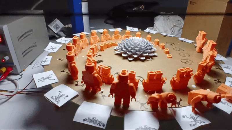
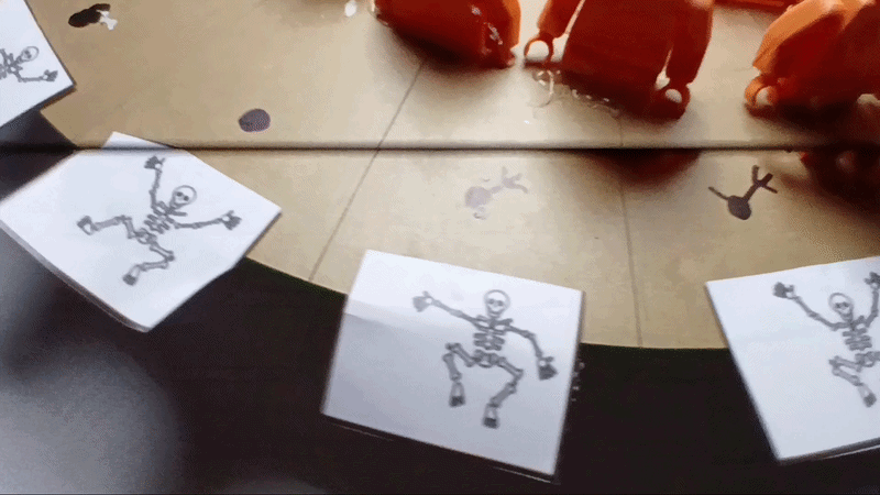
Some of the students made their own animations, I will upload them here, if any one interested. The chopped-up Lego man did not work too well, so that was a failure the skeleton worked ok. Im sure there will be more to come.