3D Printed Sumobot [Autonomous RC, Bluetooth Multiplayer]
by treyes4 in Workshop > 3D Printing
30863 Views, 169 Favorites, 0 Comments
3D Printed Sumobot [Autonomous RC, Bluetooth Multiplayer]


Finally 3D printing is now available in our country now time to make good use of this...
Autonomous part voice controlled FUNCTIONS [MODE]
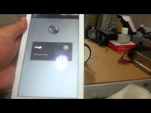
Today I updated this instructable to have autonomous functions in the same way voice activated functions to fight you opponents in the ring, by saying specific words you can challenge your self during the game and have fun while at it as you notice most sumobot games are getting boring sometimes so let us liven it up a bit by adding voice control.So now how does it work exactly well from the title itself you can tell its a combination of an autonomous sumobot with voice controlled attacks its that simple!
Normal mode
The same old program we use in sumobot competitions
What I think of the Idea and some other improvements later on ....app in the making
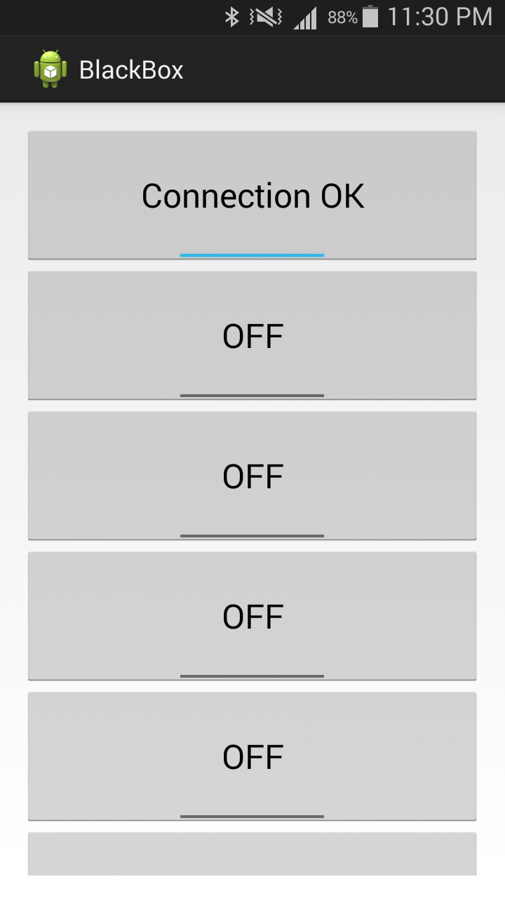
Well i think it is interesting because when I think about it the first thing that pops in my mind is "real steel" ,but in reality voice control like that is too fast in terms of response. In this project voice control response is delayed. I know this program relies on internet connection so that makes sense right I dont know about you guys if your voice control response is delayed but I'm from the Philippines where internet is slow so to make things easier for me and you guys I decided to make an android app for buttons only so far me and my brother got it to work on my phone already but this may need a lot of debugging since its our first time making an app.
Designed on 123D PROGRAM http://www.123dapp.com/design download the files in the guide and lets get started
Printed here in the Philippines --> http://zhaidazz.wix.com/3dprinter
1kg SUMOBOT RESTRICTIONS IN OUR COUNTRY "PHILIPPINES",must be within the 20x20xm range,1kg or less duhh cannot have a very sticky wheel that can grab an index card for 1 second and everything else is just like those 500g sumobot rules
My experince in building a 1KG sumobot before
weight was always the problem including the scoop and the battery getting the power and speed of the robot was easy but removing the weight was the most irritating part. Make the battery lighter you loose motor power and battery capacity. Make the scoop rigid and nice you increase its weight. Also the wiring ugh powerful motor drivers like mine can make things messy inside. Making a DIY sensor board direct soldering everything is just a mess and maintaining it is just a drag so I designed this robot to lessen those issues
Good points about this robot
Its more spacious than most 1kg sumobots out there.
Lighter
More sensors can be mounted
More space for battery upgrades
maintenance is easier
wiring is also a lot easier
Parts you will need
HUBS For my tamiya wheels with "12mm hex" 1st or 2nd
"TAMIYA WHEEL SET"
SHARP LONG range sensors 20-150cm
Arduino MINI/Nano
FTDI programmer
4S Li-Po 1300mah 132g only!
1x Pololu Dual VNH5019 Motor driver 30A (PEAK) per channel
5V regulator "UBEC" or just use a normal 7805 5v regulator UBEC is better than 7805~
3x M3 screws
M3 Flat head screws
3x M3 Nuts
1x 150mm x 180mm Fiberglass / carbon fiber plate 2mm thickness
OPTIONAL UPGRADES
HC 05 Bluetooth module <-- get this to have voice control functions
IR rx 38khz with "IR remote"
TOOLS
Dremel
Blow torch
Screw driver
Soldering iron
HOT GLUE
WIRE stripper
Downloads
CHASSIS and Basic Parts


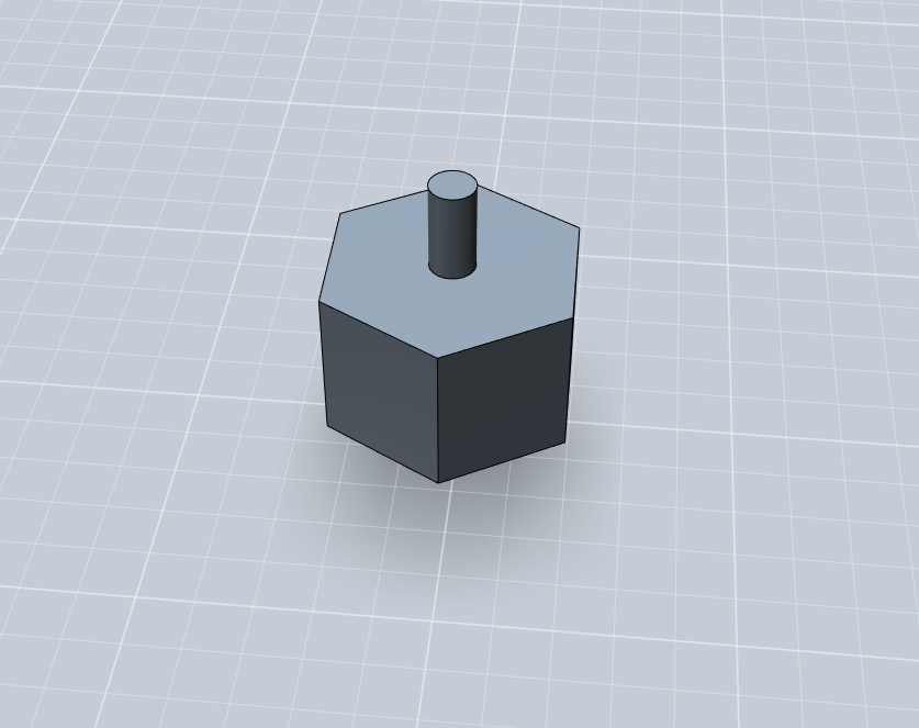
The first thing you will need is the chassis
3D print or DIY its up to you just open my 3D files to see the dimensions
just remember you chassis width should be 180mm so that you can print my robots scoop/mask with out any editing
Aluminum Brackets for Motors
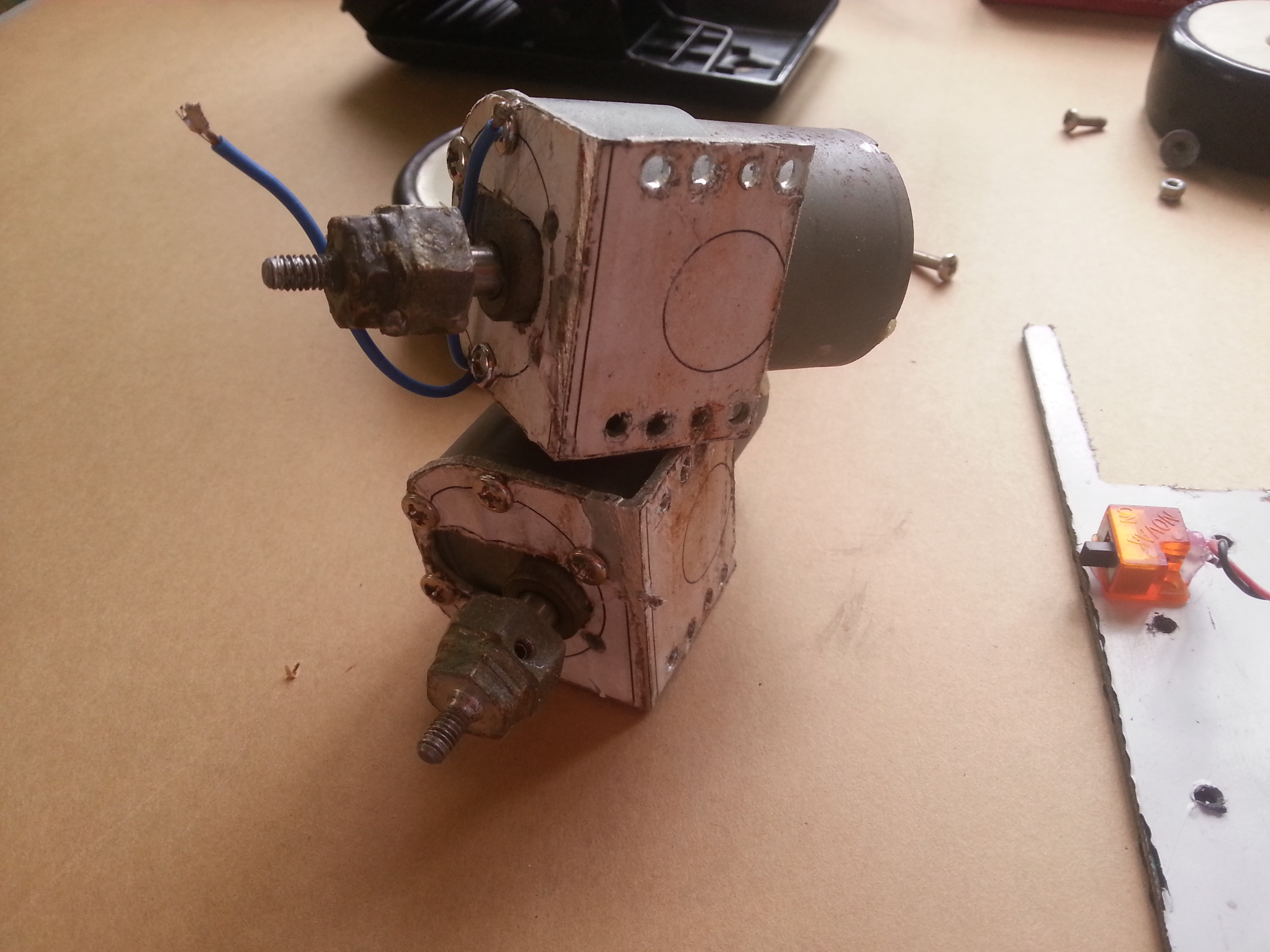


Me being cheap I decided to make my own brackets a few months ago by recycling and keeping the total cost to a minimum. What is did was I got this Aluminum L bracket and printed the layout below on a short bond papers I stick it with double side tape then placed it on one side of the bracket giving me a guide where to drill and cut
Note~
make sure the length of the whole thing is 120mm or 12cm excluding the motors attached
add a base plate to make your whole bracket solid
Downloads
1st Assembly (MOTORS, BRACKET, HUBS, WHEELS)
.jpg)


Getting excited?...
Going on now that you have a good picture of what you have or going to have
Following the pictures do the same for the other side easy right :D
3D Model 1st Assembly
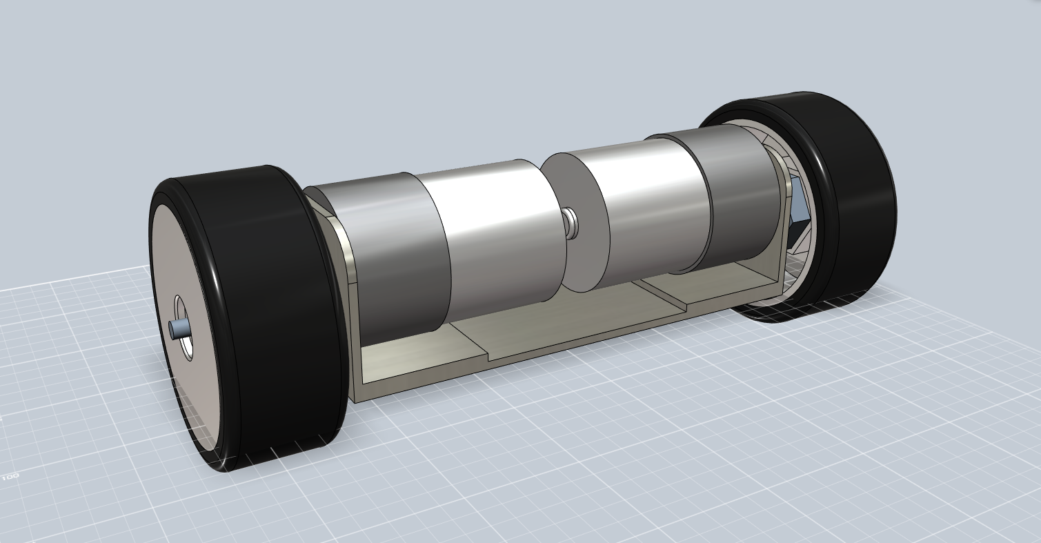
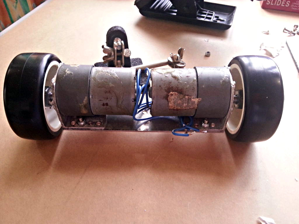
This is how it should look like after assembling it.....sorry if mine looks crappy these motors are 3 years old! the best motors you can get :D
Drilling Some Holes


I know this is a drag but here's how I made my holes on the chassis for the brackets.
drill a hole on the center of the base plate of the aluminum bracket since the width of it is 12cm i made a hole somewhere at the center of it and and I did something similar to the chassis also after that I bolted everything in place and drilled 2 random holes wherein it will set everything in place.
Review~ Things Left to Assemble or Gather


CHASSIS DONE~
DRIVE SYSTEM DONE~
ALL that is left is to
-Get a li-po battery and mount it ------------------------------------EASY
-gather all the sensors 2x SHARP 2x ground sensor----------EASY
-Arduino nano-----------------------------------------------------------EASY
-3D printed sumobot mask/scoop----------------------------------EASY
(optional) back cover 3D print Im not printing one thou --------EASY
- Screw/ glue the sensors on the sumobot mask --------------EASY
- MOTOR DRIVER-----------------------------------------------------NORMAL
-Major wiring ------------------------------------------------------------NORMAL
-Programming ---------------------------------------------------------EASY
Battery


Easy as it is feel free to buy some batteries ranging from 3S 1300mah - 1800 to 4s 1300 - 1800 mah
Since these are the only ones that will fit my design anything bigger/higher will need some minor tweaking on the robot mask
For my situation I will be using 4s 1300 mah which is just 132grams perfect for my 1 kg sumobot
SENSORS (Front)


Sensors... I know you guys know this but let me just give you the sensors I prefer for this set up. First of all if you are using long range sensors like mine it will always have a bad point wherein when something is close to it something like 5cm away it actually reads it as 50cm + away that is why its specs is called 20-150cm distance because its accuracy will only take effect 20cm away and anything closer might have a bad or inaccurate reading
so now how do we avoid that problem. Simple we buy a closer range sensor or add another sensor instead of using 2 in front we use 3 where in the third one is at the center acting as a close range sensor so that when you are pushing your enemy it can be sure that it is already hitting it compared to having 2 sensors it is not sure if its already hitting the opponent.
Anyways since this is the only available sensor for as of now I will be using 2 long range sensors but for some of you readers out there I suggest buying a shorter range sensor.
SENSOR (GROUND)

Sensors that give you the sight on the floor to detect the white line or the boarder of the ring. This will help you robot stay inside the ring and not out
So right now I am using DIY ground sensors but for most of you I would suggest buying those from pololu since its very small and easy to attach on the robot mask.
For sumobots and Line follower robots we always use digital ground sensor because it will lessen the calibration time compared to analog wherein light will interfere with the ground sensors and will cause you to change the programming values on the sensor. So to make things simple we use digital sensors wherein light wont affect its values.
Robot Mask 3D Printed~


Welp first time experience for me but I was a little disappointed since it was not 100% perfect but hey its better than nothing.
So with my robot mask design you will most likely experience the same thing.....trimming the support pillars. With the correct print setting its either you can make your life easier or harder.Going back Since you have all the basic parts its now time to explain where exactly to place and glue your parts.
First of all I would like to separate the Arduino nano from the motor driver and I want all the sensors on the robot mask also I would like to add a switch for my supply system. By looking at the picture do the same for your robot
Embed the Nuts!
.jpg)
.jpg)

CAUTION WE WILL BE DEALING WITH FIRE SO YOU KNOW BE SAFE!
So we do have holes on the robot mask right but you will find it hard mounting it on the chassis because of the tight space you have inside it especially when there are circuits inside it already.
So what I did was blow torching a nut then carefully placing it at the same hole therefore embedding the nut onto the plastic. So i did the same thing three times but I observed the end part of the nut is covered with plastic meaning if place a screw in it it will not go through since there is plactic blocking the other side so what I did was to heat up the screw for a few seconds less than 10 and the screwed it in removing/clearing the plastic that is blocking the other side of the nut.
Repeat the same thing and reinforce the embedded nuts by coating it with super glue or epoxy.
Motor Driver


Here is my old and abused Motor driver already connected To the "UBEC/REGULATOR",motors, male dean plug for the battery supply and Switch which can be located at the back.
Download the fritzing file and open it with the fritzing program to get a better look on the circuit this will apply to all the wiring
Block diagram "connection"
Battery 14.8V-->Switch positive line-->UBEC 5v-->Arduino nano
^ -->Motor driver "VIN/+" 14.8V
-------Connect One motor per channel----------
MOTOR DRIVER SPECS more on http://www.pololu.com/product/2507
Get your Arduino moving! This shield makes it easy to control two high-power DC motors with your Arduino or Arduino-compatible board. Its dual robust VNH5019 motor drivers operate from 5.5 to 24 V and can deliver a continuous 12 A (30 A peak) per motor, or a continuous 24 A (60 A peak) to a single motor connected to both channels. These great drivers also offer current-sense feedback and accept ultrasonic PWM frequencies for quieter operation. The Arduino pin mappings can all be customized if the defaults are not convenient, and the motor driver control lines are broken out along the left side of the shield for general-purpose use without an Arduino.
Downloads
Major Wiring (jointing)
.jpg)
DO not mind the wires there since im just reusing it to make new connections just continue reading and you will get through.
OK so now we are done with the stuff on the chassis now time to mess with the main arduino connections.Joint all of your sensors terminals except for the signal pin. Start from the Sharp sensors to the arduino nano in my case the gizduino mini I jointed the + and - terminals and soldered it onto the gizduino mini next I soldered the signal pins onto the Analog pins....1 sensor 1 analog pin~
Major Wiring Arduino Mini to Motor Driver


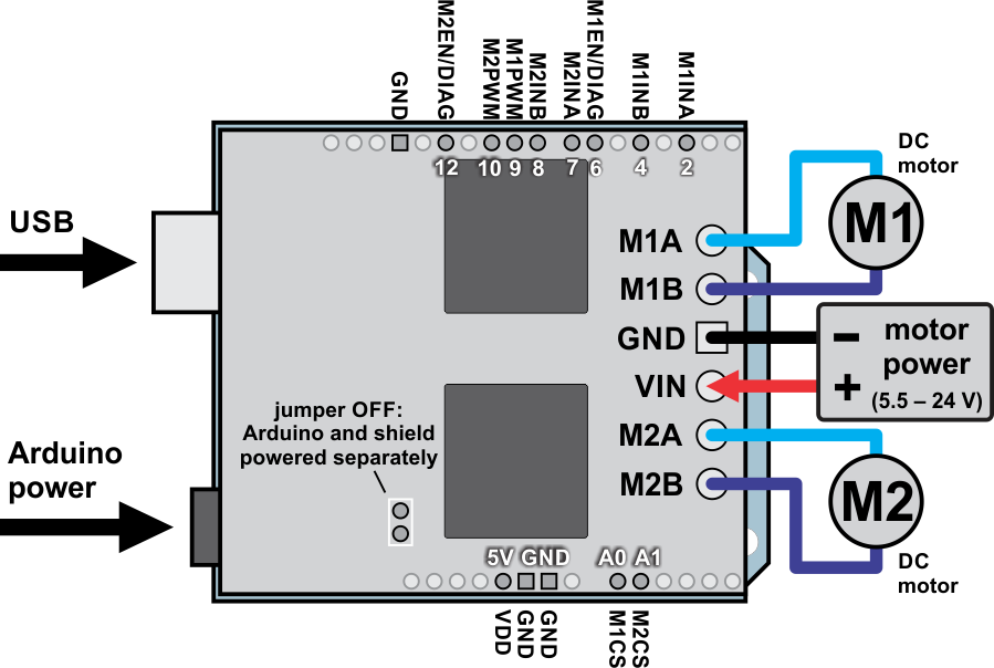
For new Motor drivers of this model cut the connection you see on A0 and A1 at the back side of the PCB since this will eat your analog pins or if you do not want to just dont bother using these pins until you understand their functions.
I wired everything up by following the images on the pololu website sow with the diagrams provided by pololu I manualy pin mapped and soldered the wires directly to the arduino mini and the then the Crimp housing following the correct arrangement of the connection
Major Wiring ARDUINO MINI UPLOADER/FTDI


since we are using an arduino Mini we do not have an uploader built on it so we get a separate module and connect the thing accordingly DTR -> DTR------TX->RX----RX->TX-----5V->5V-------GND->GND
MAJOR WIRING (GROUND SENSORS)


Since you have everything in place thing will be easier for you this time since connection for this will be shorter than the usual
So as you observe I directly solder the + and negative terminals onto near circuits making the wires shorter so the only wire you have there that is long the the signal pin which is connected to the analog pins again, solder it to the analog pin you desire and you are pretty much done
HOW IT SHOULD LOOK LIKE

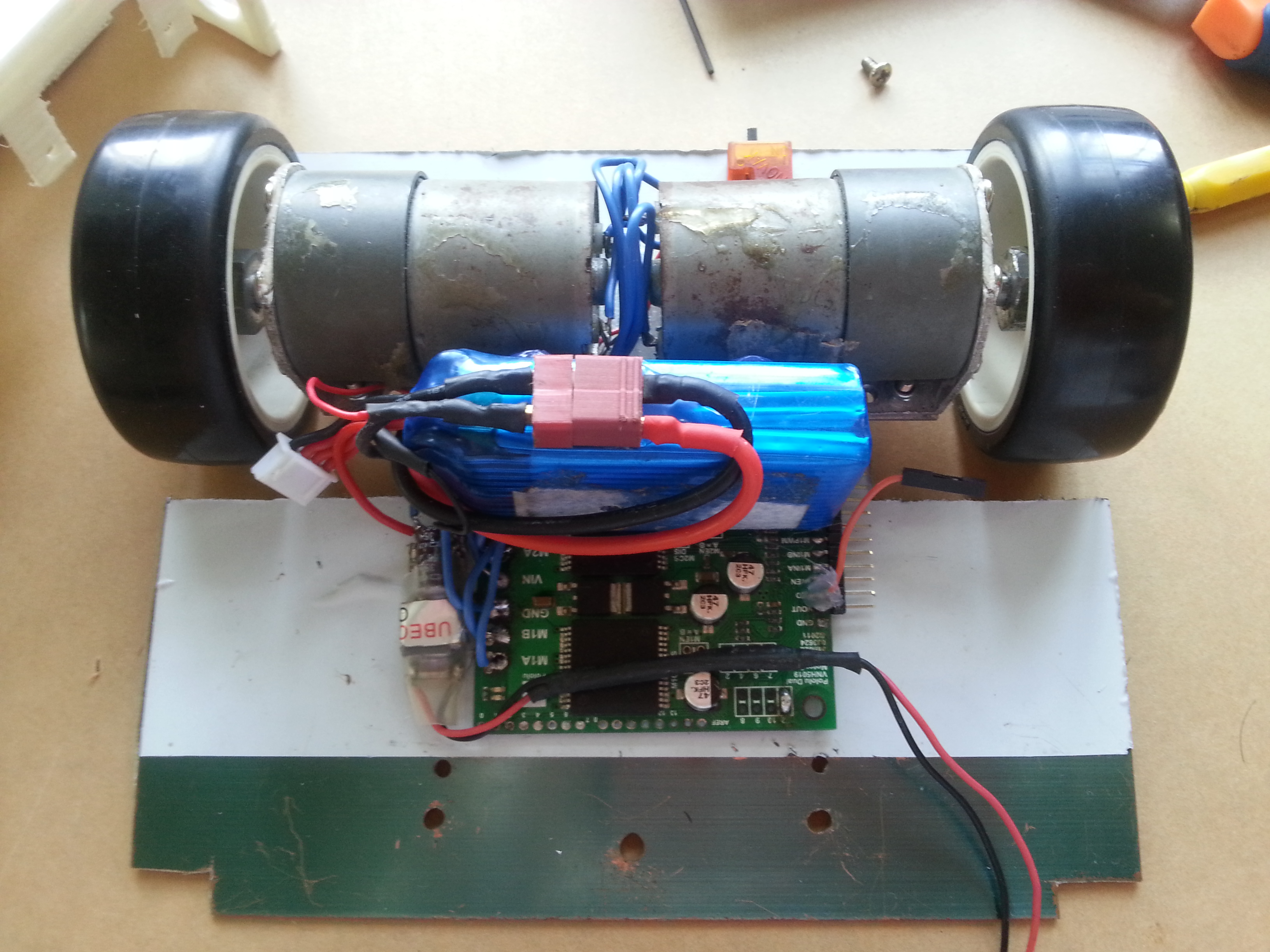
If you love making this types of robots especially sumobots you will find this build very comfortable and convenient since taking it apart is not a drag and wiring is not that messy compared to other robots out there.
HOW CONVENIENT?

So as you see its easy to take the whole thing a part with out any real drag just know where to screw things up and its good to go
OPTIONAL UPGRADES BT or IR
Now we all know these types of robots are usually autonomous but sometimes turning off a fast robot is dangerous especially if its fast and has a sharp scoop or blade. So here I have some options to shut it down where are no more enemies on the sumobot ring
1. Bluetooth a little expensive depends on the brand but gives a lot of fun features like controlling on your phone.
2 Iinfrared very cheap but nothing much to do with the controls. shutting down the robot is the only purpose here
Programming (normal Mode)
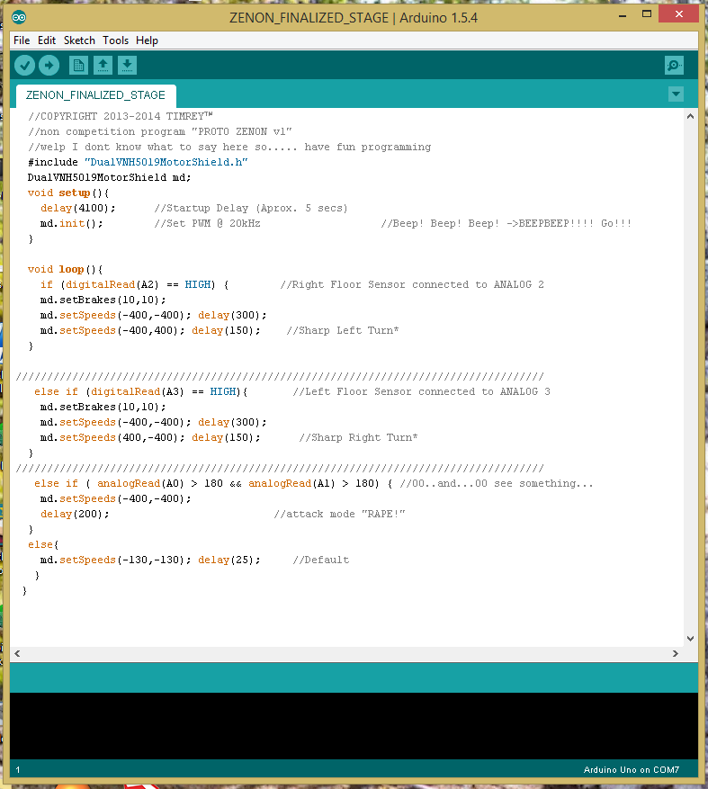
DL the library here --> https://github.com/pololu/dual-vnh5019-motor-shiel...
and paste it on the arduino libraries directory "inside the folder"
after that download the simple program I made "calibrate the values on your own"
BT and IR currently working on the program... easy but kinda lazy to make it hehehe
Downloads
Programming (Real Steel Mode)

I just made this so I hope you guys can test it out for yourself and tell me what you think.
[UPDATED]
-removed IR properties
Downloads
Android App
So here is the app my friend ASCAS introduced me to https://play.google.com/store/apps/details?id=robo...
just connect your phone to the bluetooth module and start talking, but you have to remember there are specific function names in the arduino program.
BACK COVER OPTIONAL AND SCOOP IMPROVEMENTS

Hmmmm as of now printing my back cover would be a bad idea since mounting would be a slight problem here
AND FOR the scoop you would like to fabricate your own blade for this and use hot glue to mount it after that your are ready to fight other robots with my robot design. Tnx for reading and happy printing and building :D