3DP and CNC Create a Mega Sumo Robot With Mabuchi Motors
by noclaf8810373 in Workshop > 3D Printing
3597 Views, 5 Favorites, 0 Comments
3DP and CNC Create a Mega Sumo Robot With Mabuchi Motors


This is a new type of Mega Sumo Robot that combines 3D-printed parts with CNC-machined components. The design prioritizes affordability to make robot-building accessible to more people. It also incorporates thoughtful design elements to inspire those learning robotics. By constructing this robot, builders can gain insights into product design, learning how to optimize for the strengths and weaknesses of different manufacturing methods and materials. The robot is powered by a Mabuchi motor [RZ-735VA]. While coreless servo motors like those from MAXON offer superior performance for Mega Sumo Robots, their high cost limits accessibility. By using the Mabuchi motor, which costs roughly one-tenth as much as a MAXON motor, this robot enables more people to participate in robot-building.
NOTE: Due to the use of the Mabuchi motor [RZ-735VA], the robot has the following limitations:
Short Continuous Operation Time: The Mabuchi motor [RZ-735VA] has a core rotor, resulting in a high rotor moment of inertia. This makes it unsuitable for applications requiring frequent starts and stops in a short period. Each start and stop generates large currents in the motor and control circuits, leading to rapid overheating. To prevent this, keep operation times under one minute and always monitor the motor, control circuits, and battery for overheating.
Short Motor Lifespan: Due to the frequent start-stop cycles, which are not ideal for this motor, its lifespan is reduced. Those who practice extensively with the robot may need to keep several spare motors on hand.
Supplies
3D printer
- Print range of 200 x 200 x 200 (mm) or more.
- The printer must be able to print ABS or PETG filament.
Hand tools
- Drill Bit 1.6mm
- Drill Bit 2.3mm
- Drill Bit 2.5mm
- Drill Bit 3.0mm
- Drill Bit 3.2mm
- Drill Bit 5.0mm
- Drill Bit 5.1mm
- Hand Drill
- Hand Reamer 11mm H7
- Adjustable Tap Reamer Wrench Handle
- Screwdriver JIS Cross Head No0
- Screwdriver JIS Cross Head No1
- Screwdriver JIS Cross Head No2
- Screwdriver Hex 1.5mm
- Socket Wrench Screwdriver 8.0mm
- Diamond Precision File
- Precision File
- Precision Side Cutter
- Pliers
- Snap-off Utility Knife
- Hot Melt Glue Gun
- Sand Paper
- Soldering Iron
- Machine Vise
- Scissors
- Stainless steel Scraper
- Cut-resistant gloves
Purchased parts
- 3D Printer Filament ABS or PETG
- Super glue
- Masking tape
- Double-sided Tape
- Brake Parts Cleaner
- PERMATEX Screw Lock Red
- Soldering Wire
- Parts described in Parts list
Print 3D Printed Parts


Follow these steps to print the 3D printed parts.
Procedure:
- Refer to the parts list to identify the components to be 3D printed.
- Prepare 3D print data (STL or 3MF files) from the provided 3D data file (3DP_Mabuchi_V2_Share v5.f3d) for each component.
- For the jig used to connect the shaft and gear, [Jig 16T-48T], use the provided STL file.
- Consult the reference diagram to set the correct layer orientation during printing.
- Set the layer pitch to 0.2 mm (nozzle size: 0.4 mm).
- Set the infill rate to 30%, adjusting as needed based on the slicer software.
- Use ABS or PETG filament. ABS offers higher impact resistance than PETG but is harder to print. Advanced engineering plastics can be used but require more expensive 3D printers. Avoid fiber-reinforced filaments due to their lower impact resistance.
NOTE:
- The size of small holes in 3D-printed parts may vary depending on the 3D printer or slicer software. Adjust the 3D data or slicer parameters as needed. The hole sizes in the original 3D data (3DP_Mabuchi_V2_Share v5.f3d) are optimized for my specific 3D printer, so strict adherence is not required. If holes are too small, use a hand drill to adjust their size.
- For multi-color 3D-printed parts, use 3MF files to include color information in the slicer software. Pre-prepared 3MF files are provided for reference, but single-color printing is also acceptable.
Safety Note: Ensure proper ventilation during 3D printing.
CNC Machining Parts


This section covers the fabrication of CNC-machined parts:
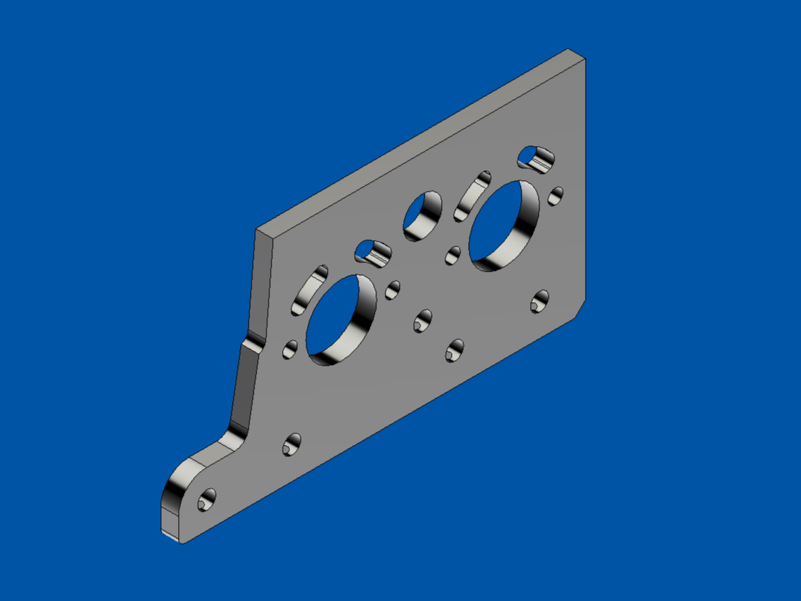
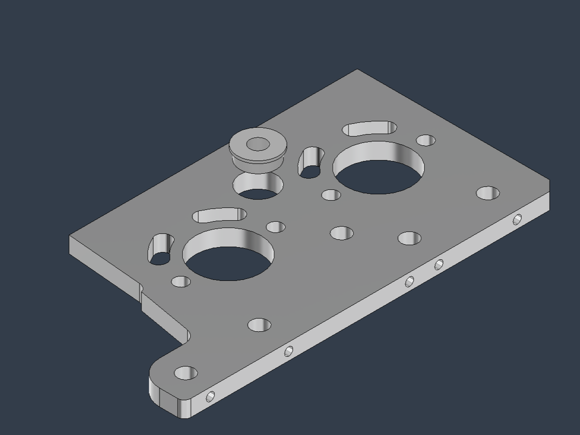
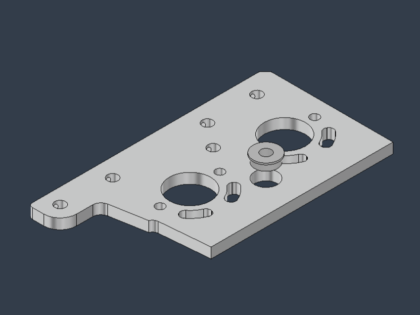
- Frame Out_V2
- Frame In_V2
If you own a CNC milling machine, refer to the 3D models and technical drawings to manufacture these parts yourself.
If you don’t have access to a CNC milling machine, you can order these parts through an online machining service. Below is a brief guide on how to place an order using an online machining service, using PCBWay as an example. However, feel free to use your preferred online machining service for the actual order. To request a quote and place an order, provide the necessary information, including 3D data (.step), technical drawings (.pdf), quantity, material type, and machining precision.
Procedure:
- Navigate to the page for entering machining quote information: https://www.pcbway.com/rapid-prototyping/manufacture/?type=1&reffercode=TOP
- Upload the 3D data files: Frame Out_V2.step and Frame In_V2.step.
- Enter the following details (refer to the screenshot of the quote input screen for guidance):
- Quantity: 2
- Design Units: mm
- Material: Aluminum 7075
- Surface Finish: Standard
- Technical Drawing: Frame_Out_V2_Holes_Drawing.pdf (Frame_In_V2_Holes_Drawing.pdf)
- Threads and Tapped Holes: Yes
- Tolerance: ±0.05
- Surface Roughness: 250 µin / 6.3 µm Ra
- Product Description: DIY Entertainment >> Robot components
- Once you’ve entered the information for both parts, submit the request and await the quote. If the quote is satisfactory, proceed with the order. Note that you’ll need to create an account with the online machining service in advance.
NOTE:
These parts include holes with tight fit tolerances (H7) required for securing ball bearings. Poor machining precision may prevent proper assembly. Some online machining services may not support the precision needed for these fit tolerance holes. In such cases, consider ordering parts with slightly undersized holes and finishing them yourself. You can use a tool like a hand reamer to achieve H7 tolerance for these holes: https://a.co/d/cPoyeZ8
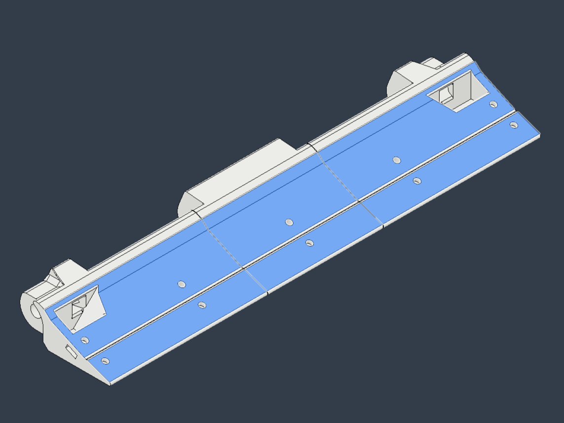
No5 Blade_200x23x2


The No5 Blade_200x23x2 is a commonly used blade in Mega Sumo Robots. This robot uses one new [No5 Blade_200x23x2] and four used [No5 Blade_200x23x2 (Second Hand)] blades. Incorporating used [No5 Blade_200x23x2 (Second Hand)] blades helps reduce costs. However, if used blades are unavailable, you can create parts with the same shape by referring to the 3D model as an alternative.
Safety Note:
The sharp edges of the four [No5 Blade_200x23x2 (Second Hand)] blades must be blunted to prevent injury. Use a diamond file or a grinder to smooth the edges. Wear protective gloves during this process.
Sanding 3D-Printed Parts


Sand the surfaces of the following 3D-printed parts that come into contact with the blade to achieve a smooth and even finish:
- Blade base C_3DP
- Blade base L_3DP
- Blade base R_3DP
The surfaces of 3D-printed parts can be wavy or uneven, so sanding ensures the blade makes proper contact with the dohyo (sumo ring surface). Sand other surfaces as needed for a polished finish.
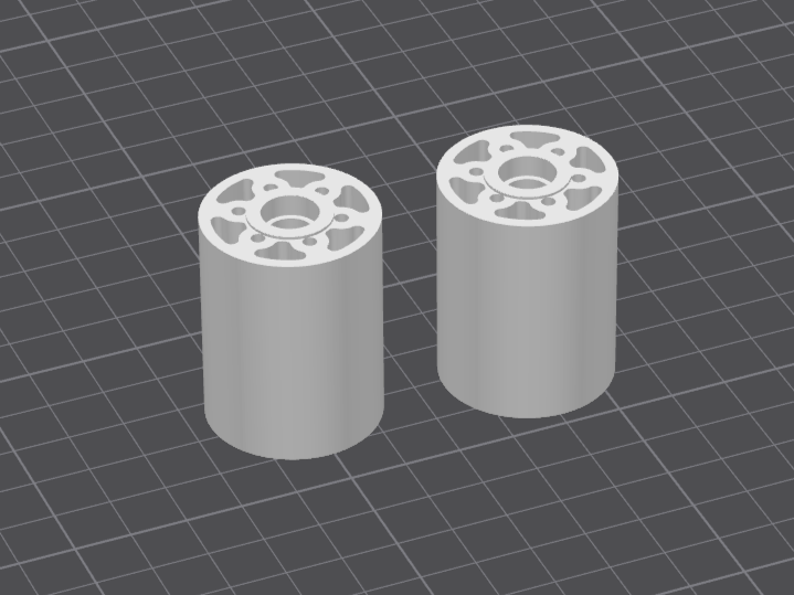
Installing Bearings

Attach bearings to the following components:
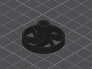
- Rim_3DP
- Frame In_V2
- Frame Out_V2
For Rim_3DP: Install [DDL-1050ZZ] bearings onto two [Rim_3DP] parts.
- Place a [DDL-1050ZZ] bearing into one side of the [Rim_3DP] hole.
- Press the bearing fully into place using a machine vise.
- Place another [DDL-1050ZZ] bearing into the opposite side of the [Rim_3DP] hole.
- Press this bearing fully into place using the machine vise.
For Frame In_V2: Install [DDLF-1150ZZ] bearings onto two [Frame In_V2] parts.
- Insert a [DDLF-1150ZZ] bearing into the hole of the first [Frame In_V2].
- Press the bearing fully into place using a machine vise.
- Insert a [DDLF-1150ZZ] bearing into the hole of the second [Frame In_V2], on the opposite side from the first.
- Press this bearing fully into place using the machine vise.
- If the [DDLF-1150ZZ] bearing is not secure, apply PERMATEX Screw Lock Red to the bearing and hole, then resecure.
For Frame Out_V2: Install [DDLF-1150ZZ] bearings onto two [Frame Out_V2] parts, following the same steps as for [Frame In_V2].
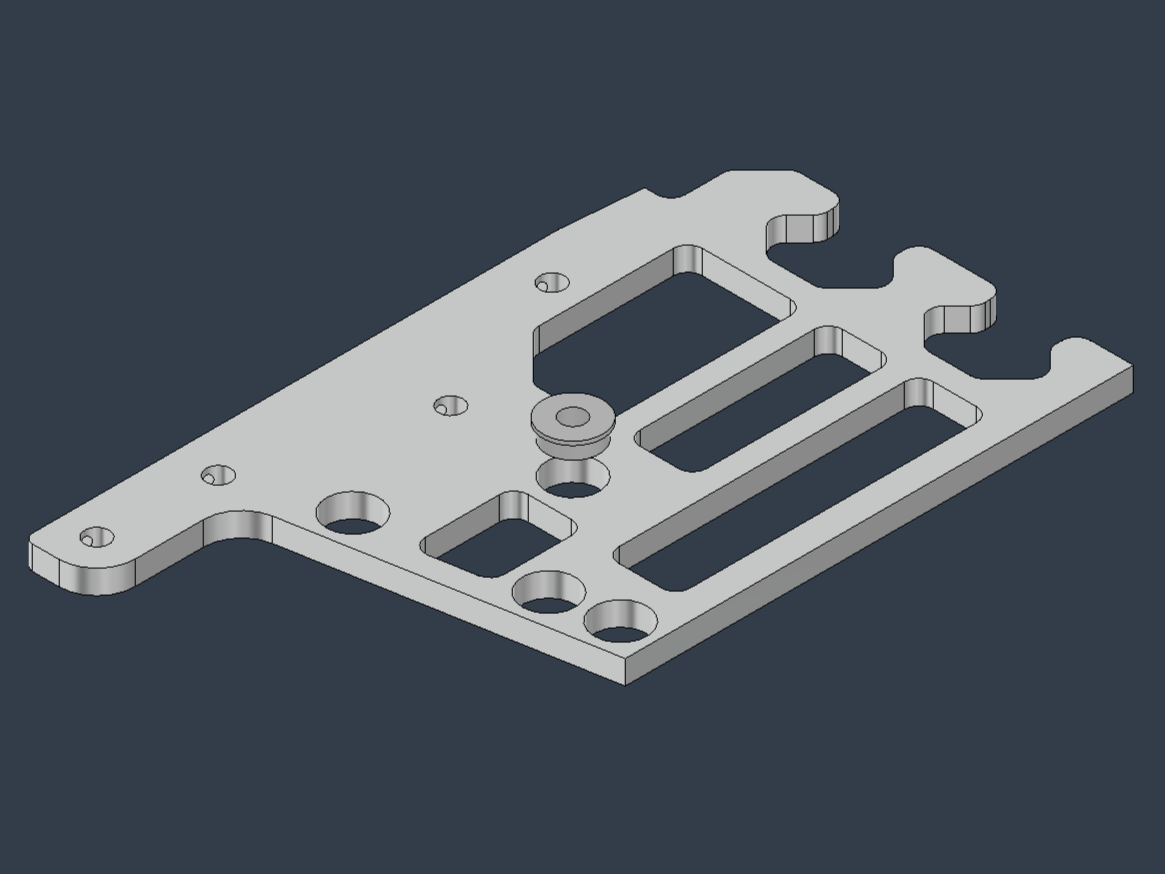
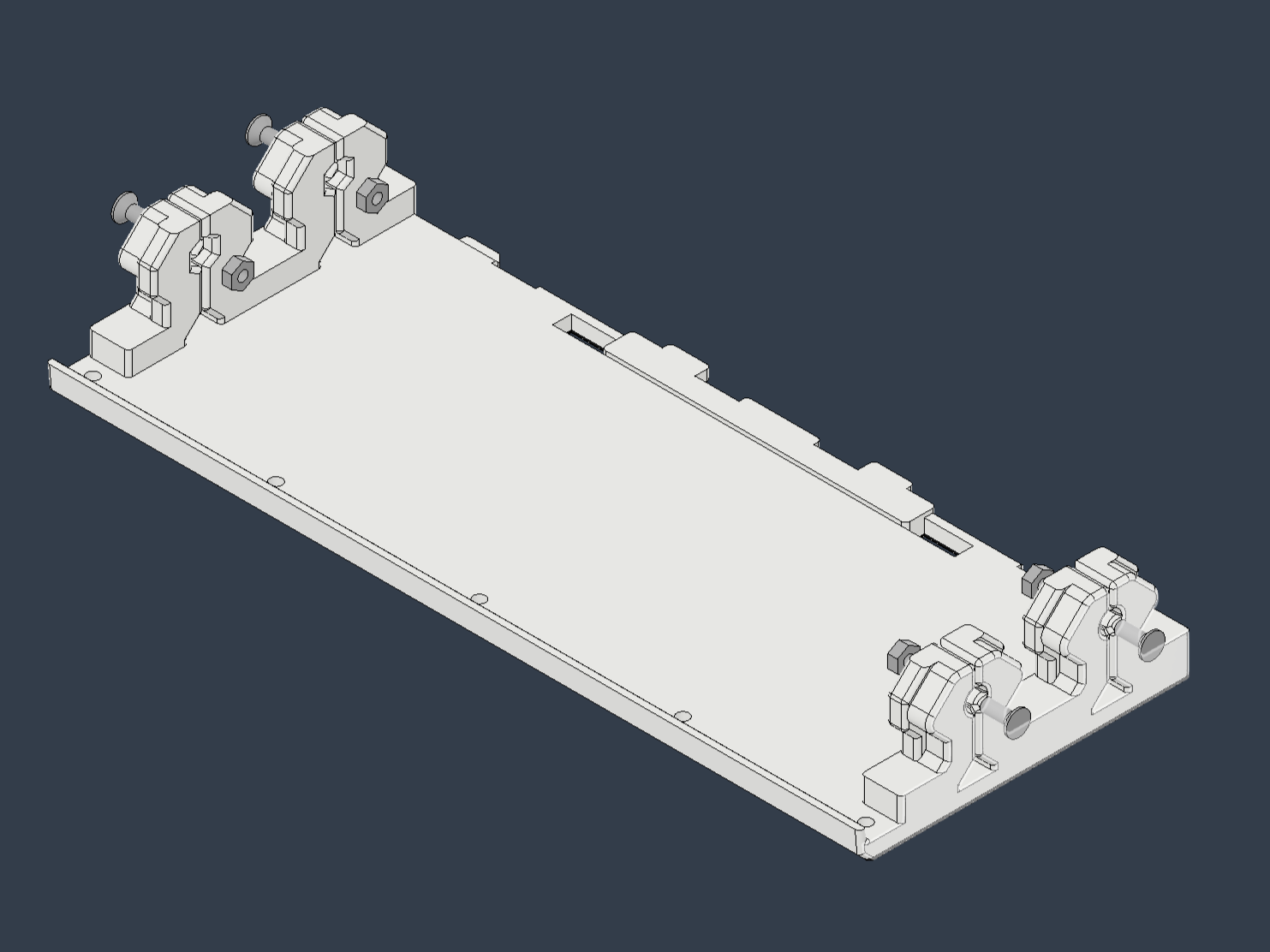
Installing Set Screws
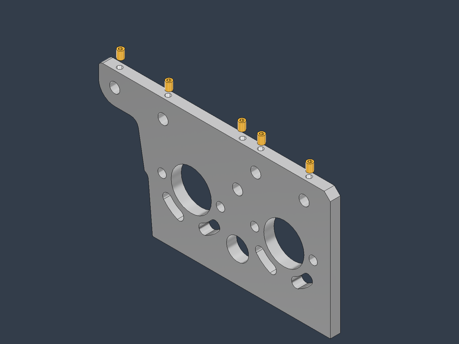
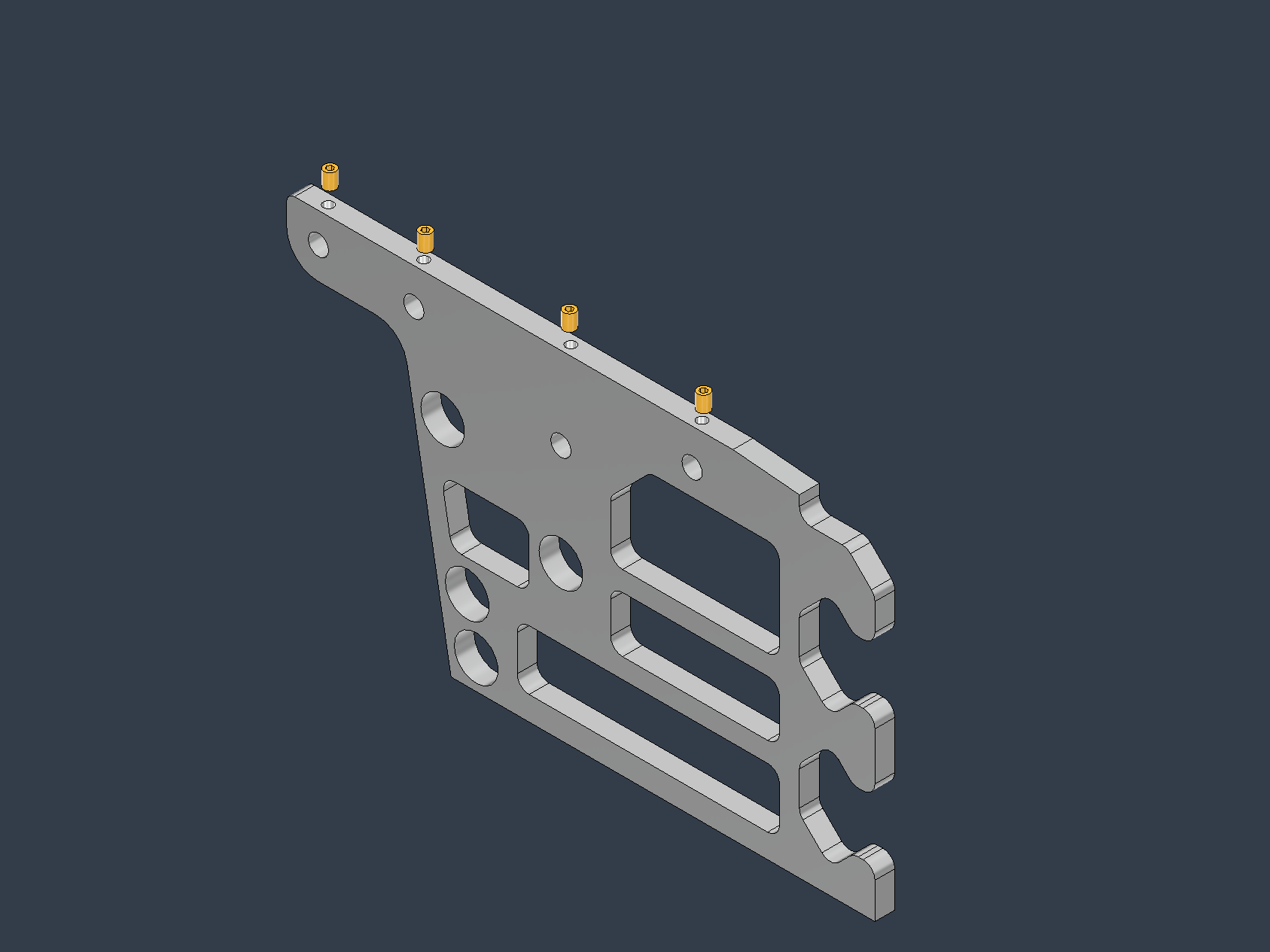
Attach set screws to the following components:
- Frame In_V2
- Frame Out_V2
Procedure:
- Install [Set screw M3L4] into the five screw holes on each of the two [Frame In_V2] parts.
- Install [Set screw M3L4] into the four screw holes on each of the two [Frame Out_V2] parts.
Cutting and Cleaning Tire Rubber
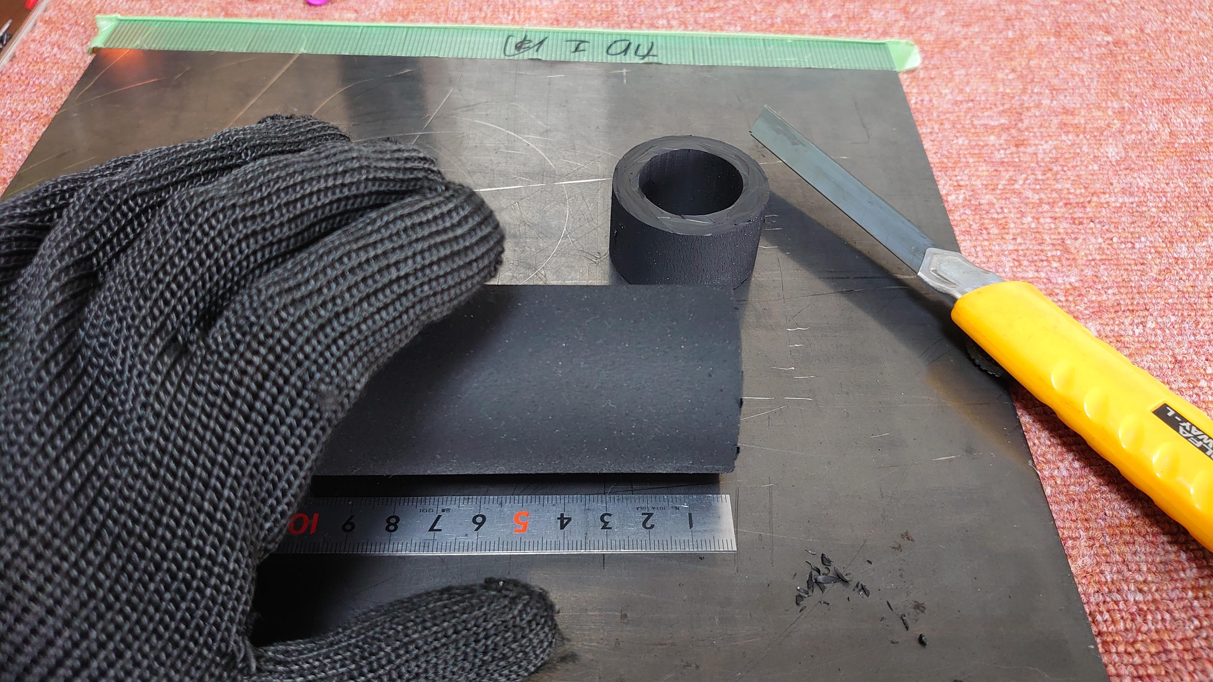
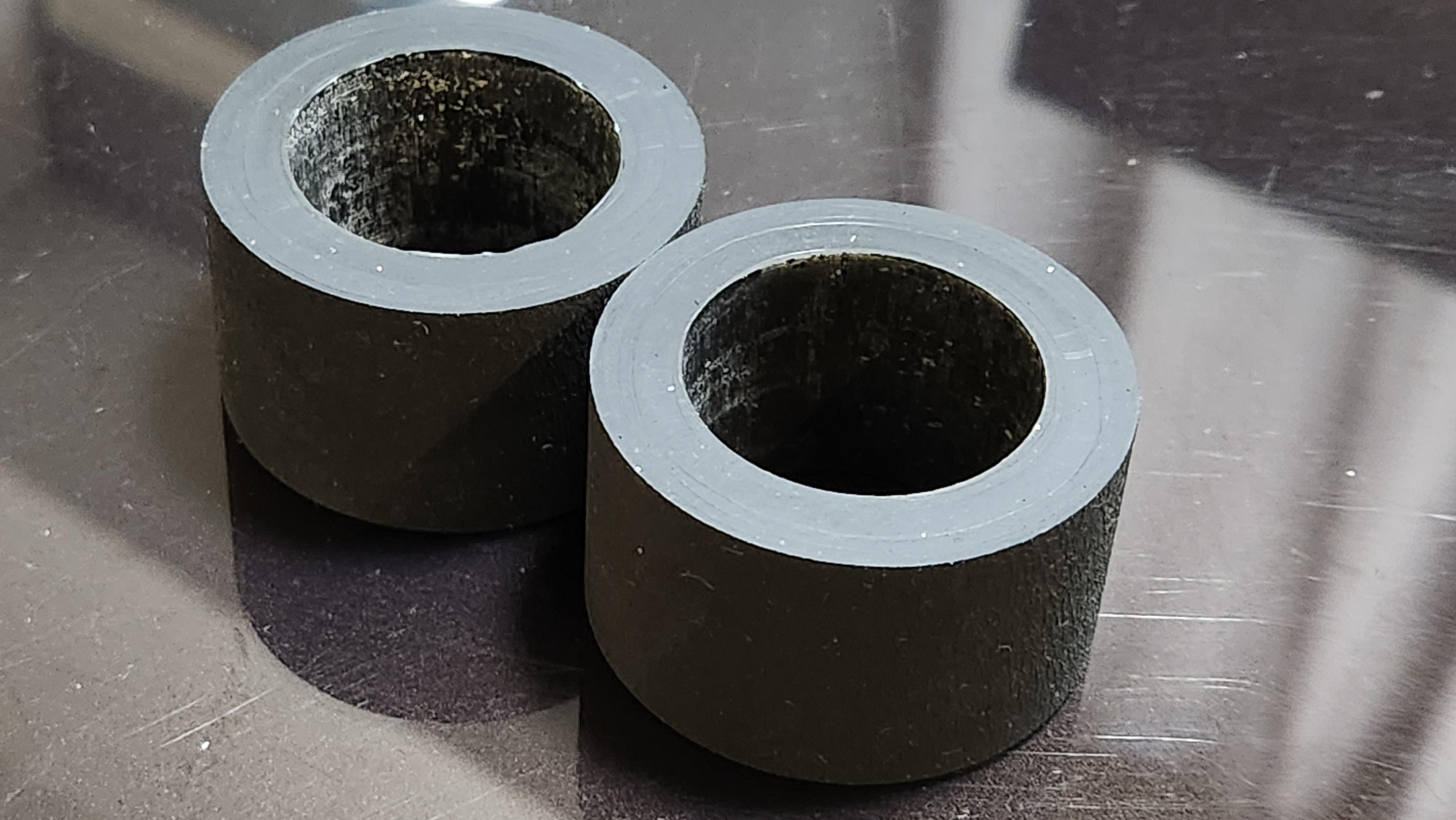

Cut rubber tubing to create two [Tire_45x30x25] pieces.
Procedure:
- Cut a rubber tube with an outer diameter of 45 mm and an inner diameter of 30 mm to a width of 25 mm.
- Clean the inner surface (bonding surface) of the [Tire_45x30x25] pieces using Brake Parts Cleaner.
Safety Note: Wear cut-resistant gloves to prevent injury.
Wheel Assembly


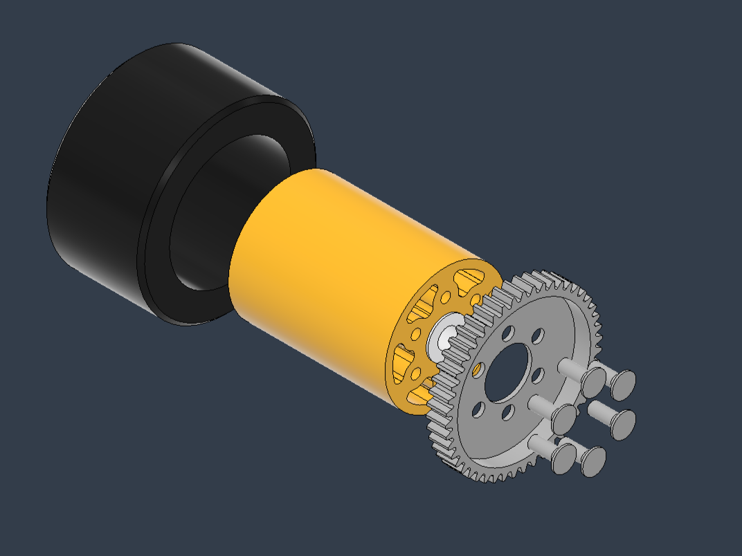
Complete the Wheel Assembly by bonding the tire rubber and attaching the gear.
Procedure:
- Fit [Tire_45x30x25] onto [Rim_3DP].
- Bond [Tire_45x30x25] to [Rim_3DP] using super glue.
- Attach [Rim_3DP] to [0.8 Module (32 Pitch) 48T Steel Spur Gear Ø12mm] using [Flat head screw_M3L08].
Safety Note: Use super glue in a well-ventilated area.
Gear Assembly
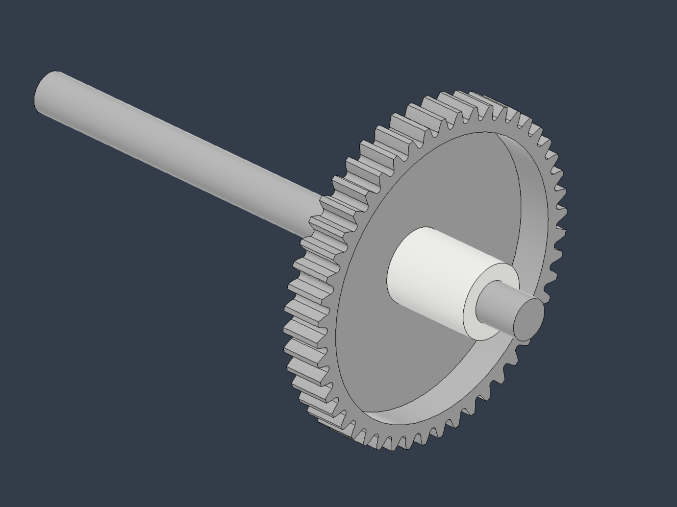
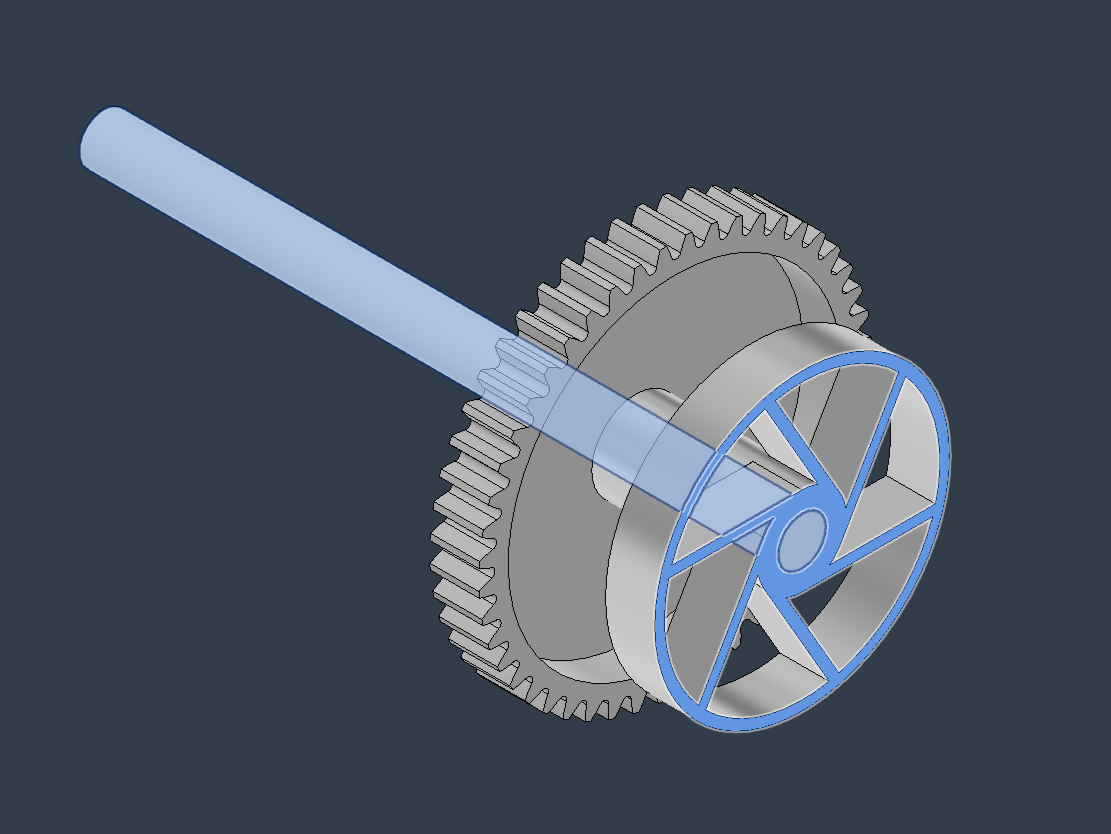
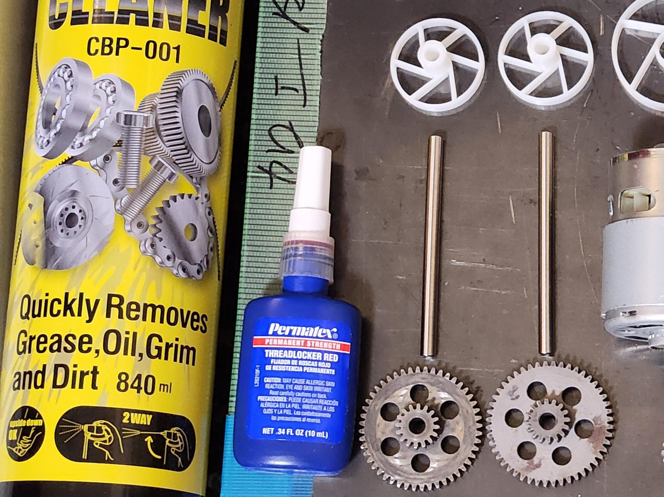


Assemble the Gear Assembly by combining the gear [Concentric Ultra Light Double Gear (0.8 Module 16T-48T) Ø5mm] with the shaft [Shaft 5x71].
Procedure:
- Clean the surface of the [Shaft 5x71] with Brake Parts Cleaner.
- Clean the hole of the gear with Brake Parts Cleaner.
- Apply PERMATEX Screw Lock Red to the surface of the shaft and the gear’s hole.
- Rotate the [Shaft 5x71] while sliding the gear to its designated position.
- Wipe off any excess PERMATEX Screw Lock Red.
- Secure the gear’s position using the [Jig 16T-48T]. Align the bottom of the jig with the shaft’s base and ensure the jig contacts the gear to position it correctly.
- Allow PERMATEX Screw Lock Red to cure for at least one day.
- Once cured, wipe off any excess PERMATEX Screw Lock Red.
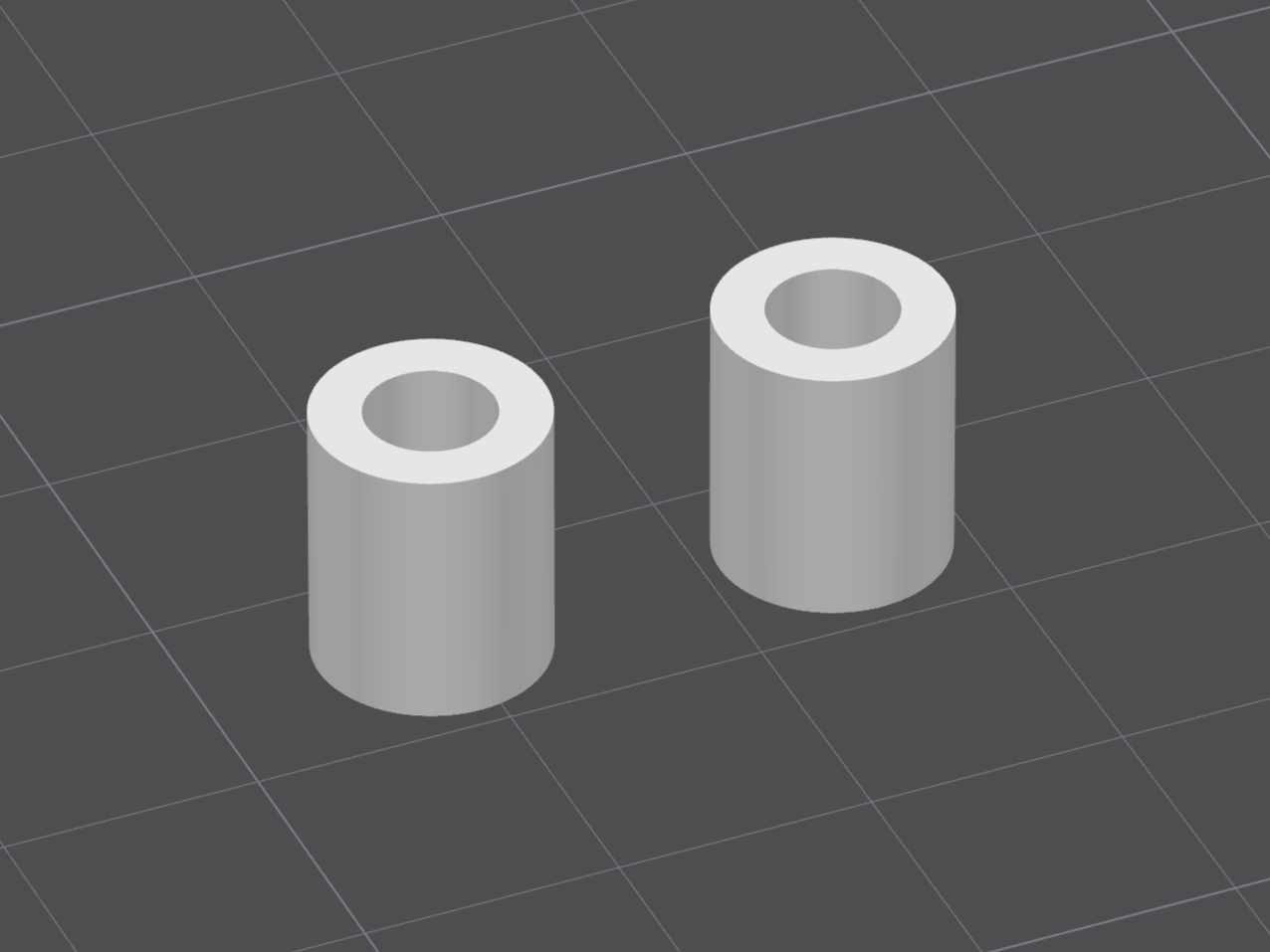
- Attach the [Spacer Large_3DP] to the shaft to complete the Gear Assembly.
NOTE:
If the gear and shaft connection is weak, the most likely cause is an excessive gap between the gear’s hole and the shaft. Reducing the diameter difference between the gear’s hole and the shaft to 0.05 mm or less may improve the connection.
Motor and Pinion Gear Assembly


Attach the pinion gear [RC 32P Hardened Pinion Gear 5mm Shaft 19T Motor Gears Carbon Steel] to the shaft of the motor [RZ-735VA-9517].
Procedure:
- Seal the motor’s bearing with masking tape to prevent PERMATEX Screw Lock Red from adhering to it.
- Clean the motor shaft surface and the pinion gear’s hole with Brake Parts Cleaner.
- Apply PERMATEX Screw Lock Red to the motor shaft and the pinion gear’s hole.
- Rotate the pinion gear while attaching it to the shaft.
- Wipe off any excess PERMATEX Screw Lock Red.
- Allow PERMATEX Screw Lock Red to cure for at least one day.
- Once cured, remove the masking tape used for sealing.
- Wipe off any remaining excess PERMATEX Screw Lock Red.
NOTE:
If the pinion gear and shaft connection is weak, the most likely cause is an excessive gap between the pinion gear’s hole and the shaft. Reducing the diameter difference between the pinion gear’s hole and the shaft to 0.05 mm or less may improve the connection.
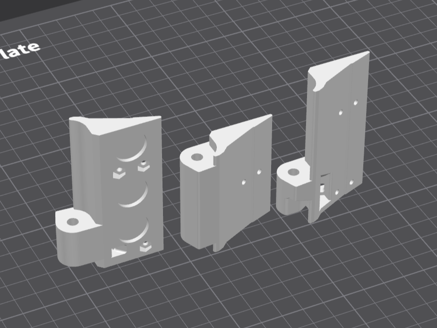
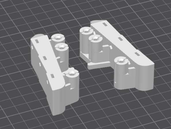
Screw and Nut Installation
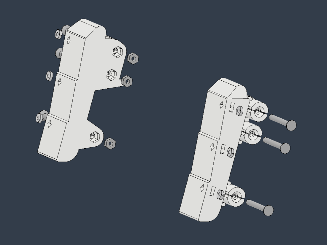


Embedding Nuts in Parts
Embed nuts into the following parts:
- Armor Joint L_3DP
- Armor Joint R_3DP
- Blade base C_3DP
- Blade base L_3DP
- Blade base R_3DP
- Inner_C_3DP
- Inner_LB_3DP
- Inner_LF_3DP
- Inner_RB_3DP
- Inner_RF_3DP
Steps: Referring to the photos or 3D data, insert [Nut_M2.6 Type 3] into the holes of the parts.
- Secure the nut’s position using [Flat head screw_M2.6L10 No.0 Type 1].
- Fill the hole containing the nut with a Hot Melt Glue Gun.
- Once the hot melt glue has hardened, remove the screw.
- Trim any excess hot melt glue with a Snap-off Utility Knife.
Attaching Screws and Nuts to Parts
Attach screws and nuts to the following parts:
- Armor Joint L_3DP
- Armor Joint R_3DP
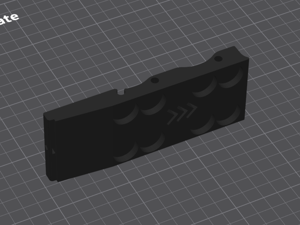
- Rear Cover_3DP_Multicolor
Steps: Referring to the photos or 3D data, insert [Nut_M3t2] into the holes of the parts.
Secure the nut from the opposite side with a screw to prevent it from coming loose. Use [Flat head screw_M3L25] for [Armor Joint L_3DP] and [Armor Joint R_3DP]. Use [Flat head screw_M3L08] for [Rear Cover_3DP_Multicolor].
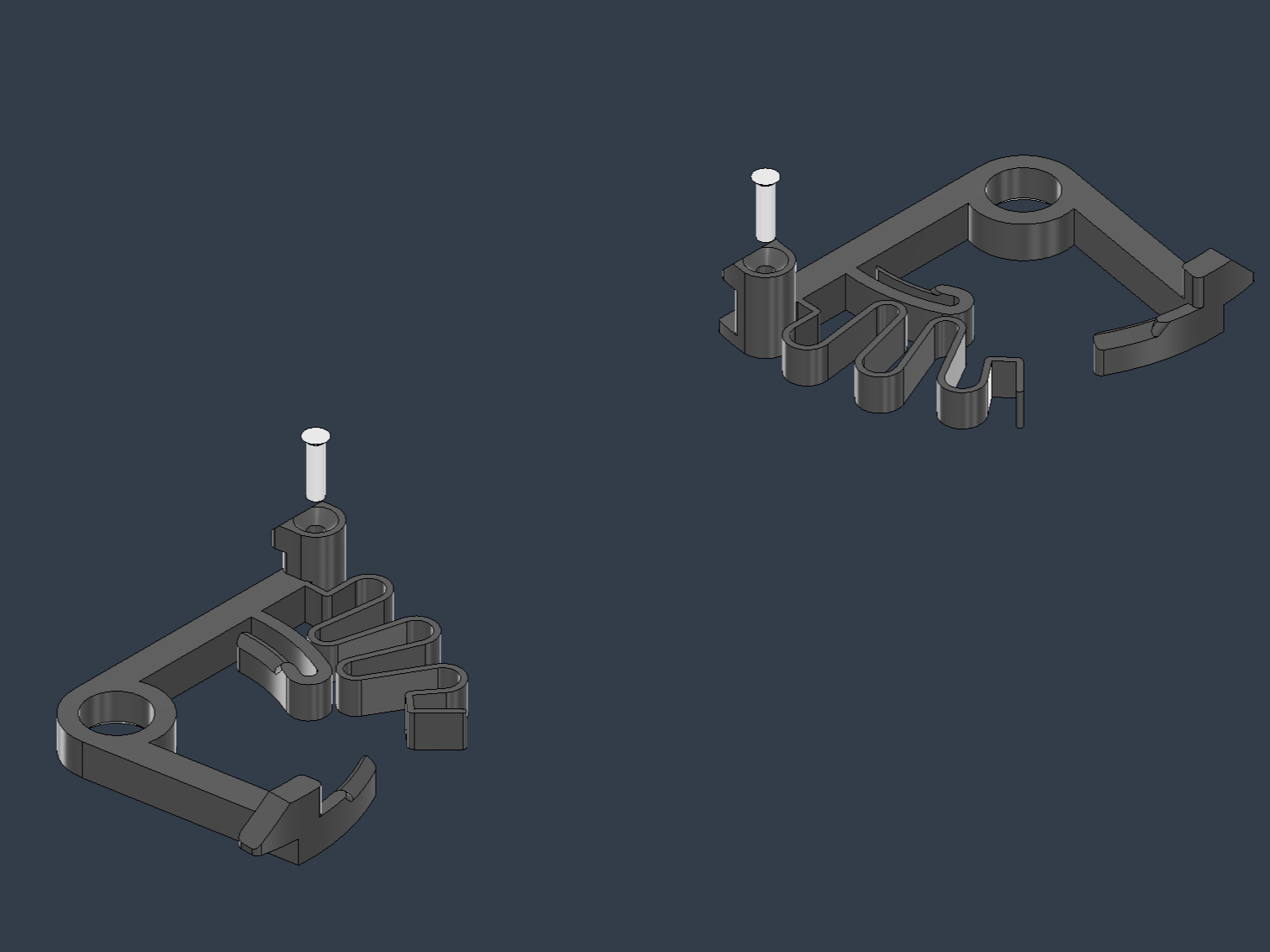
Attaching Screws to Parts
Attach screws to the following parts:
- Lever_L_3DP
- Lever_R_3DP
Steps: Referring to the photos or 3D data, insert [Flat head screw_M2.6L10 No.0 Type 1] into the holes of the parts using a self-tapping method. These screws reinforce the strength of the parts.
NOTE: If the hole is too small for self-tapping, use a 2.3 mm hand drill to adjust the hole size.
Magnet Bonding


Bond magnets to the following parts:
NOTE: Please refer to the color indication on the 3D model for the polarity of the magnets.
- Blade base C_3DP
- Blade base L_3DP
- Blade base R_3DP
- Inner_C_3DP
- Inner_LB_3DP
- Inner_LF_3DP
- Inner_RB_3DP
- Inner_RF_3DP
Procedure:
- Sand the magnet-bonding surfaces of each part to ensure a smooth, even finish.
- Insert a magnet into the prepared hole and verify that the magnet’s surface is flush with the part’s surface. If the magnet protrudes, repeat step 1.
- Clean the magnet-bonding surface of each part.
- Sand the bonding surfaces (bottom and sides) of the magnet with sandpaper. Creating fine scratches on the magnet’s surface increases bonding strength.
- Clean the magnet’s bonding surface with adhesive tape, such as masking tape.
- Apply a thin layer of super glue to the magnet-bonding surface of the part, working on one area at a time.
- Insert the magnet into the area with super glue.
- Hold the magnet firmly in place until the super glue sets.
- Repeat steps 6–8 for all magnets until they are fully attached.
- Fill any gaps between the magnet and the hole with super glue.
- Allow the super glue to cure for at least one day.
- Once cured, remove excess super glue using a stainless steel scraper or snap-off utility knife. Wear cut-resistant gloves to prevent injury.
Safety Note:
This process involves handling multiple strong magnets, which can cause unexpected accidents due to their magnetic attraction. If you are unfamiliar with handling strong magnets, learn proper handling techniques before starting.
Tips:
Before bonding, attach magnets to a thin iron plate to prevent sudden movement due to magnetic forces. After bonding each magnet, place a non-magnetic, thick material (e.g., a Rubber Sheet) over it to maintain distance between magnets, reducing the risk of accidents caused by magnets attracting each other.
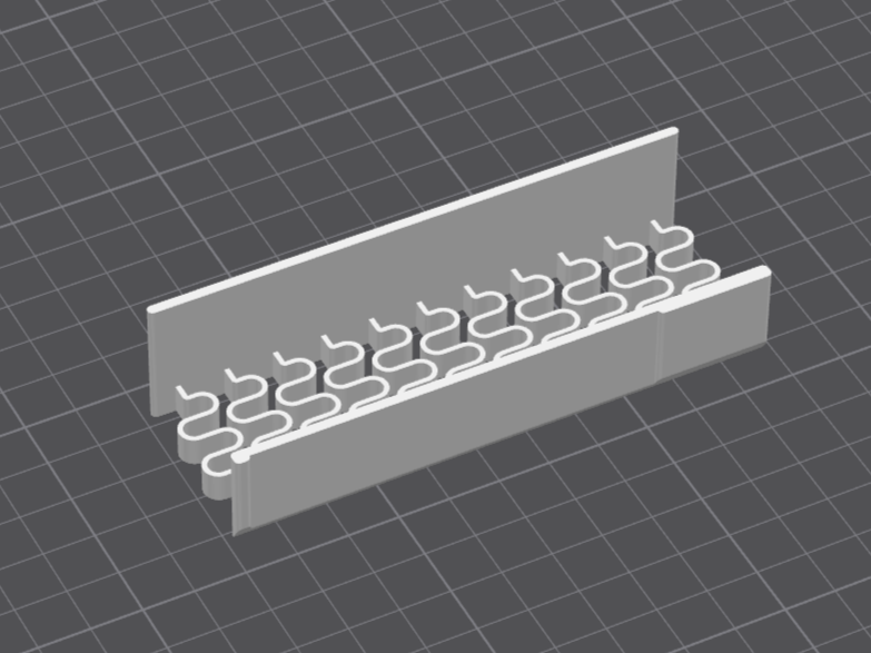
Wiring the Motor and Control Unit


Wire the following components with reference to the provided photos and circuit diagram:
- Motor [RZ-735VA-9517]
- Motor Driver [Motor driver 12-48V 100A]
- Control Board [Universal board 4*6 and Arduino nano]
- RC Receiver [MR-8_KO_PROPO]
Procedure:
- Solder an XT30 male connector to the motor’s wiring.
- Solder wires with an XT30 female connector to the output terminals (A and B sides) on the back of the motor driver.
- Solder the [+] side of a wire with an XT60 male connector to the [+] power terminal on the back of the motor driver.
- Solder a wire with a [#10 Ring Terminals Connector] to the [-] power terminal on the back of the motor driver.
- Attach a [#10 Ring Terminals Connector] to the [-] side of the wire with the XT60 male connector.
- Referring to the circuit diagram, create a connector harness for the RC receiver and connect it to the RC receiver.
- Referring to the circuit diagram, assemble the control board.
- Write the program [Share_3DP_Mabuchi_V2_nano.ino] to the Arduino nano on the control board.
- Referring to the circuit diagram, create a connector harness to connect the control board to the motor driver.
NOTE:
Arrange the control circuit components to avoid interference with other parts, referring to the 3D model. The Control Unit shown in the reference photos is a prototype and may include extra parts not listed in the Parts List. Do not rely too heavily on the photos.
Safety Note:
- Perform soldering in a well-ventilated area to avoid inhaling fumes.
- Handle the soldering iron with care to prevent burns, and place it in a safe location after use.
- Since high-voltage (12-48V) components are involved, verify proper insulation of all wiring to prevent short circuits.
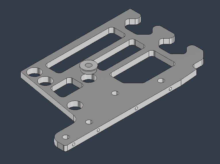
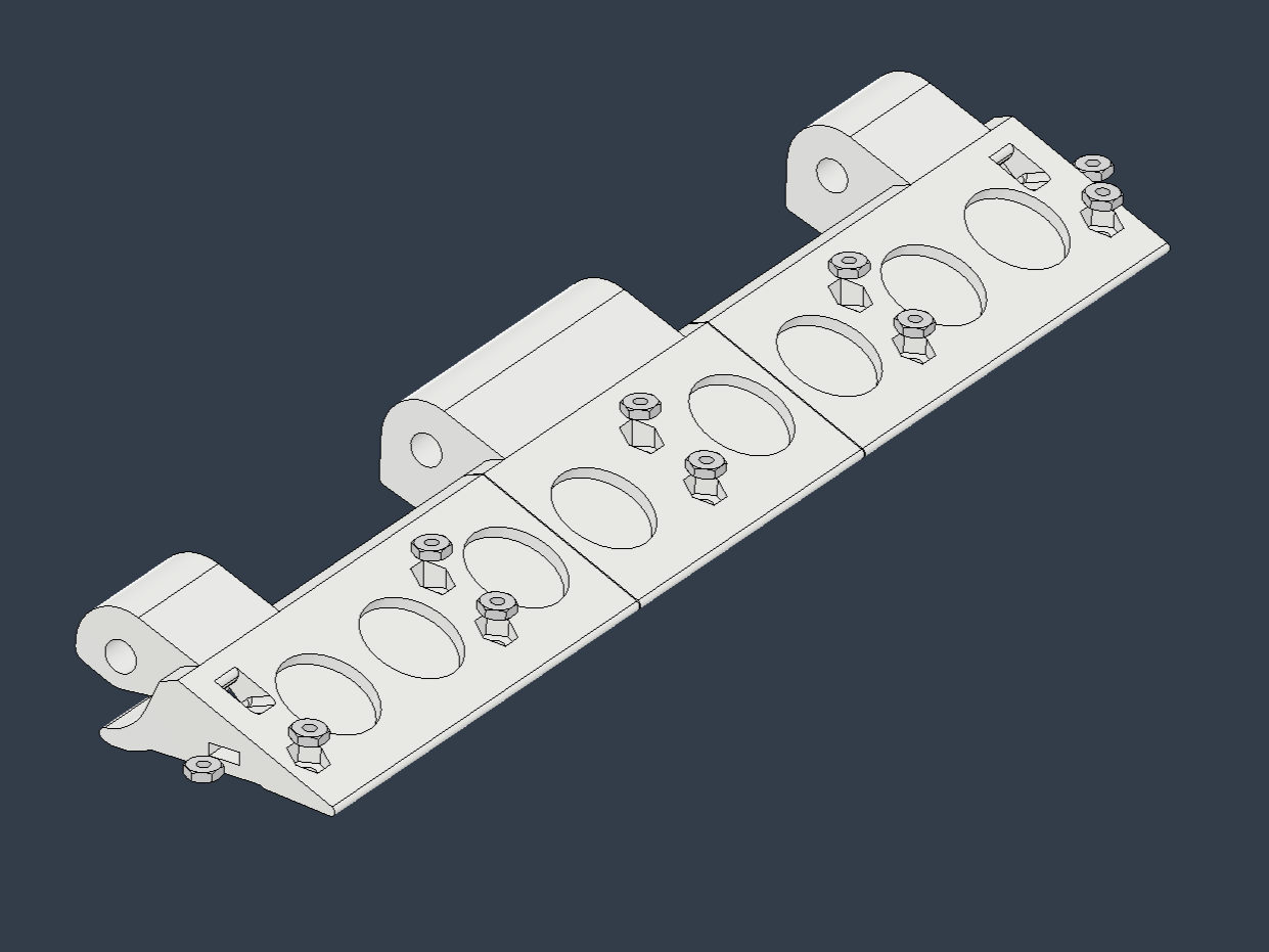
Assembling the Control Unit


Attach the following components to the [Inner_T_Basic] to complete the Control Unit:
- Fuse [Fuse 80A]
- [Hex bolt M5 L16]
- [Nut_M5]
- [Spring washer M5]
- [Washer M5 D10]
- Motor Driver [Motor driver 12-48V 100A]
- Control Board [Universal board 4*6 and Arduino nano]
- RC Receiver [MR-8_KO_PROPO]
- [Pan head screw M3L6]
- [Pan head screw B tight 2x6]
Mounting the Motor Driver:
- Secure the [Inner_T_Basic] to the Motor Driver using two [Pan head screw M3L6].
Installing the Fuse:
- Attach the [Hex bolt M5 L16] and [Nut_M5] to the [Inner_T_Basic].
- Insert the following onto the [Hex bolt M5 L16] in this order: [Washer M5 D10], harness with ring terminal, Fuse, [Washer M5 D10], [Spring washer M5].
- Fasten them with the [Nut_M5].
Mounting the Control Board:
- Secure the [Inner_T_Basic] to the Control Board using four [Pan head screw B tight 2x6].
- Connect the Control Board to the Motor Driver with a connector harness.
Installing the RC Receiver:
- Attach the [Inner_T_Basic] to the RC Receiver using double-sided tape.
- Connect the RC Receiver to the Control Board with a connector harness.
Note:
The Control Unit shown in the reference photos is a prototype and may include extra parts not listed in the Parts List. Do not rely too heavily on the photos.
Assembling the Robot
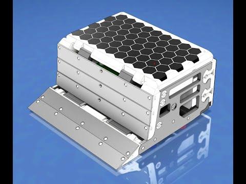
Assemble the robot using videos and 3D models as reference.