48V 2kW Electric Go Kart
by EduardoGE in Workshop > Electric Vehicles
147 Views, 2 Favorites, 0 Comments
48V 2kW Electric Go Kart
Hello everyone!
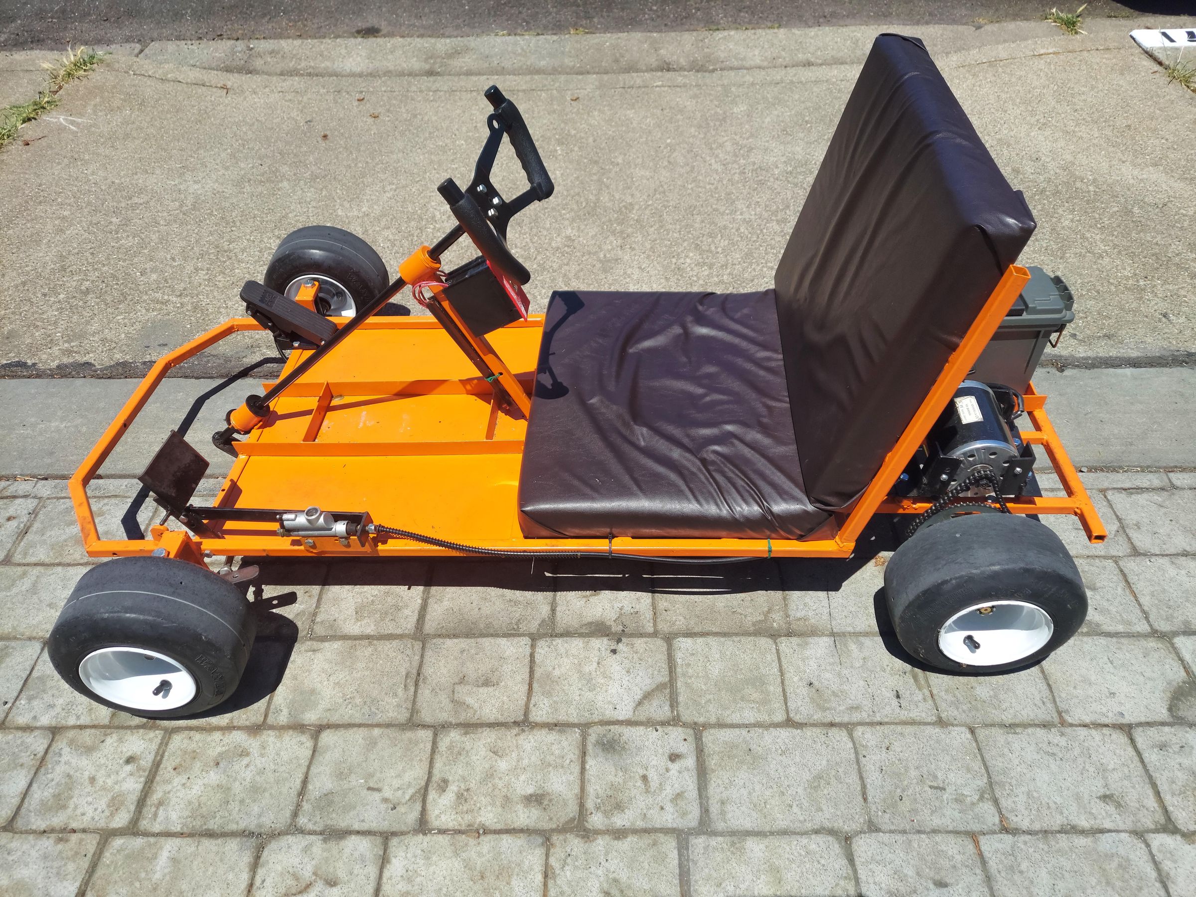
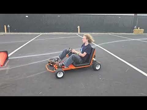
This project aims to build an electric go kart from scractch capable of reaching 25 MPH with 2 hours of run time.
The project is completely Open Source meaning all the CAD files are avaliable to download for free in case you require any modifications. The difficulty is beginner freindly but with a slight learning curve in which will put your skills to the test.
The kart is designed for a maximum speed of 25 MPH with a maximum weight capacity of 200lb not including the kart itself.
The total time to build one of these is about 1-2 months depedning on skill and amount of time dedicated.
During the build, it is highly recommended to have Autodesk Fusion installed in your computer/laptop. This will a lot since there are some steps which have complex geometries which might make it more difficult to follow. Having the entire 3D model opened allows to check geometries, dimensions, or quick modifications to your build.
This Instructables is quite long so there might be a few small corrections needed and appreciate any feedback. Will try to monitor and update this post to keep it as updated as possible.
If you have any questions, feel free to reach out to me through Discord: redxdeath.
Supplies
The bill of materials features all the main components needed to build this vehicle. Some smaller parts were left out as most home workshops have these items or can be found easily at a local hardware store such as nuts, bolts, wire, heat shrink, etc. The bill of materials was created on Google Sheets and can be opened using the follwoing link
https://docs.google.com/spreadsheets/d/1MrFU5IRz84HG7-wxN5bdzNhRp7kOhv8i/edit?usp=sharing&ouid=109972728628304982323&rtpof=true&sd=true
Front Frame
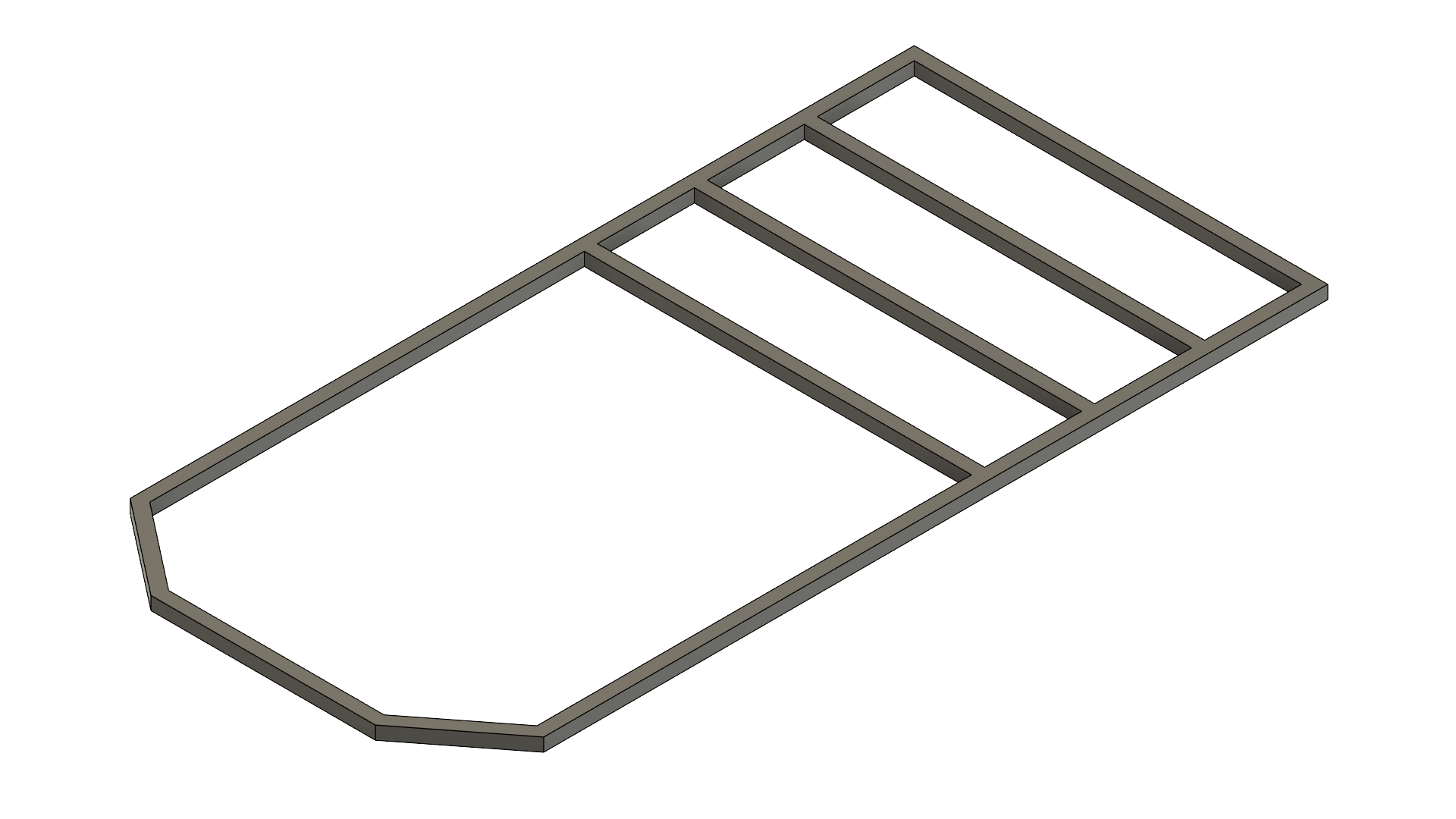
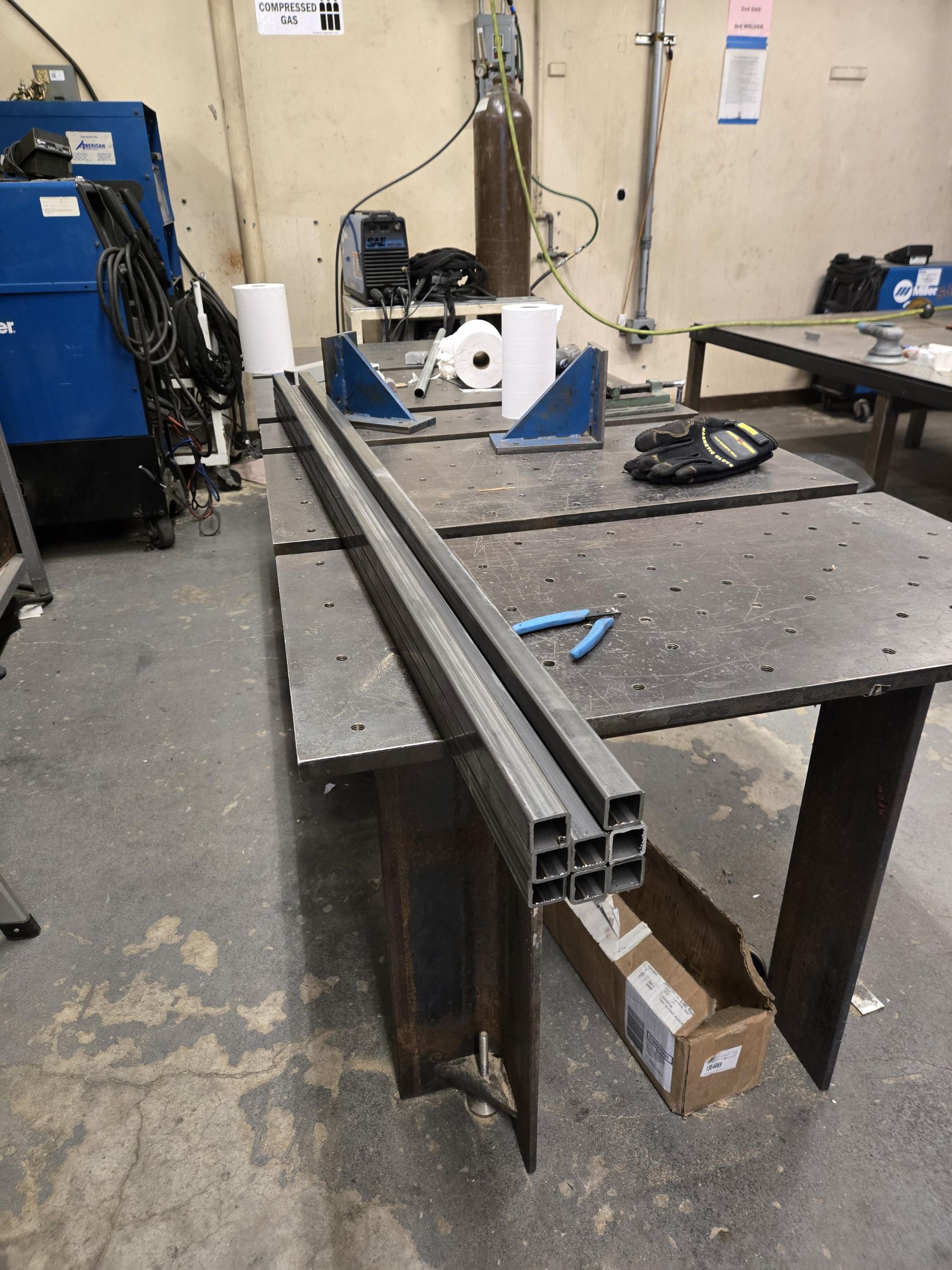
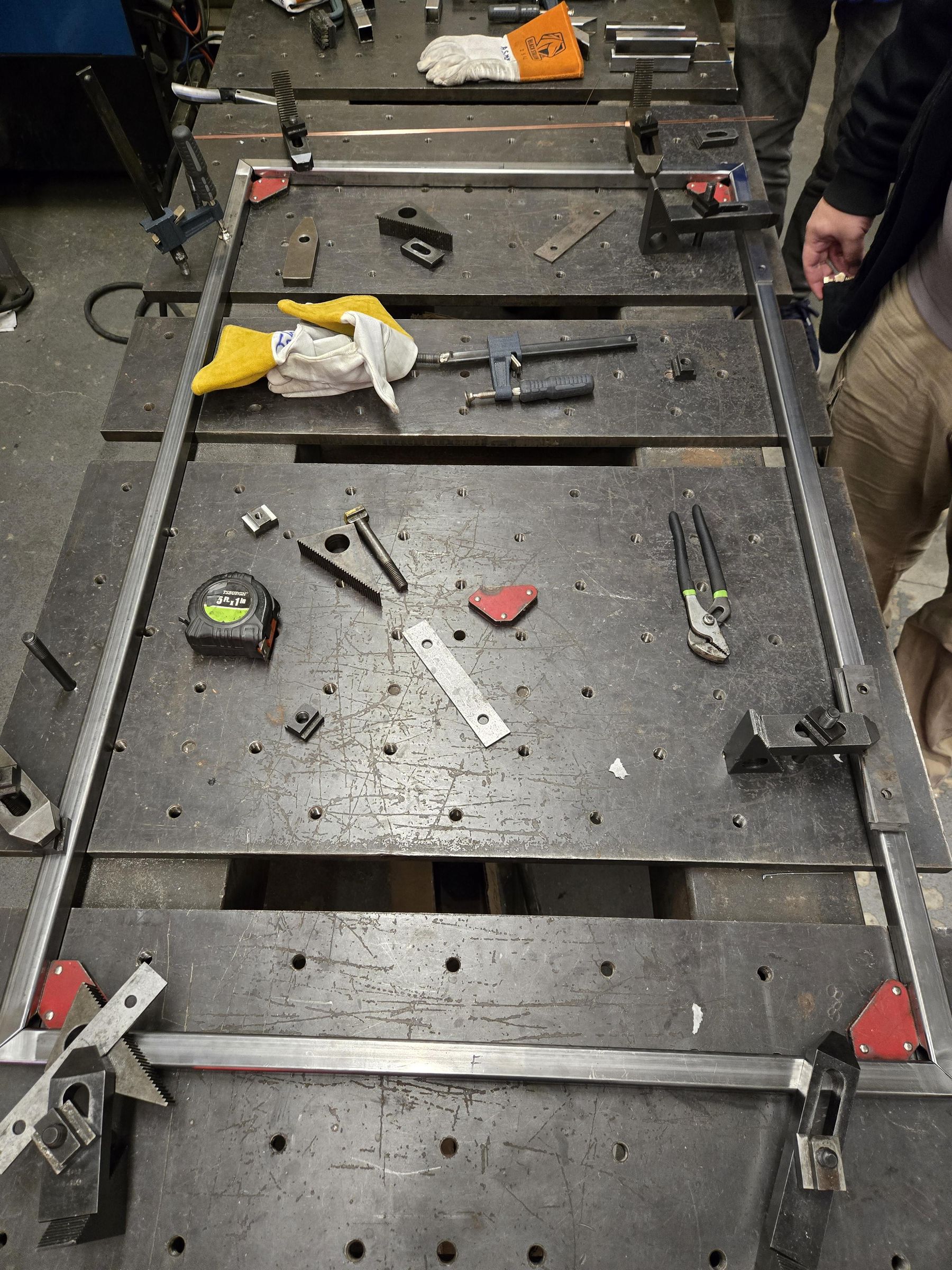
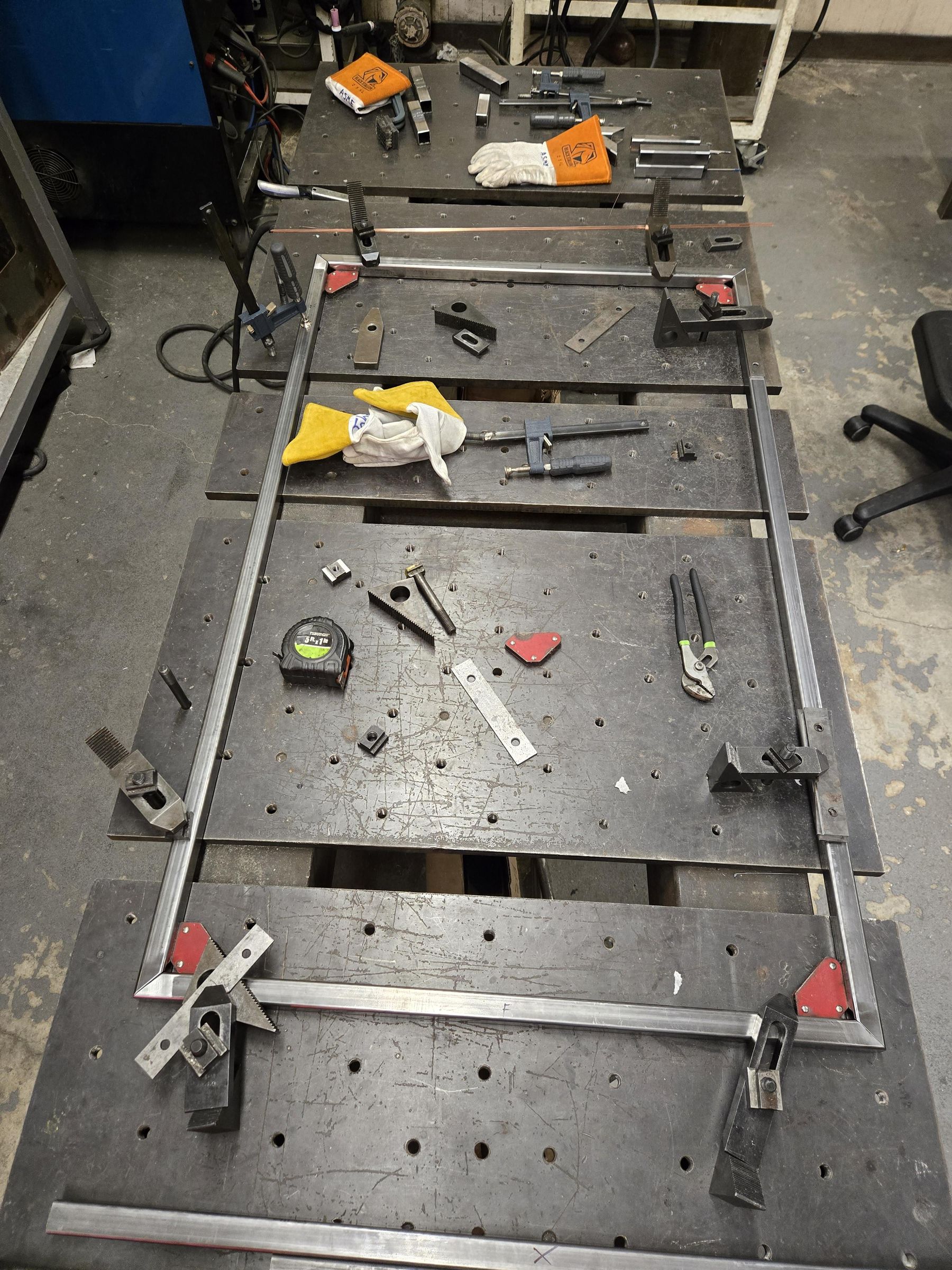
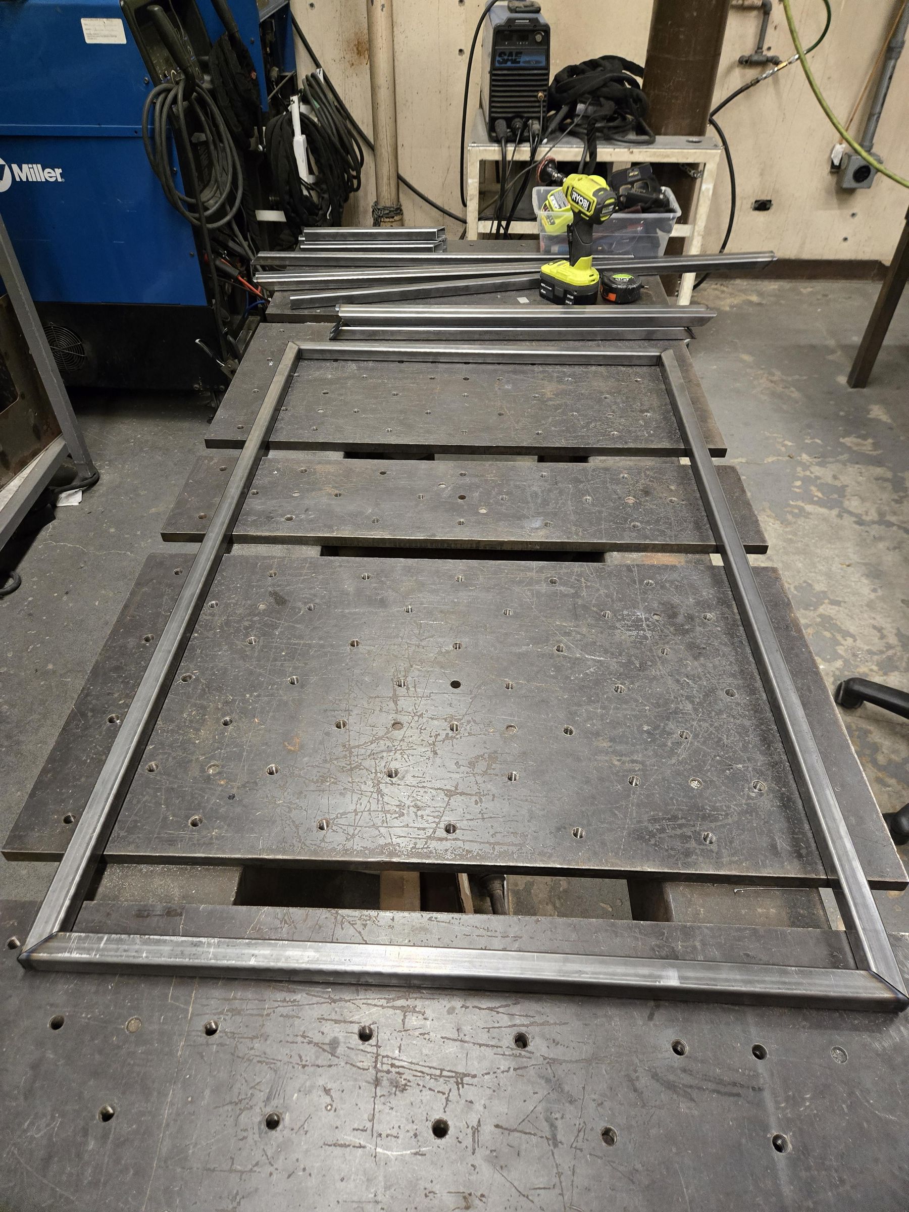
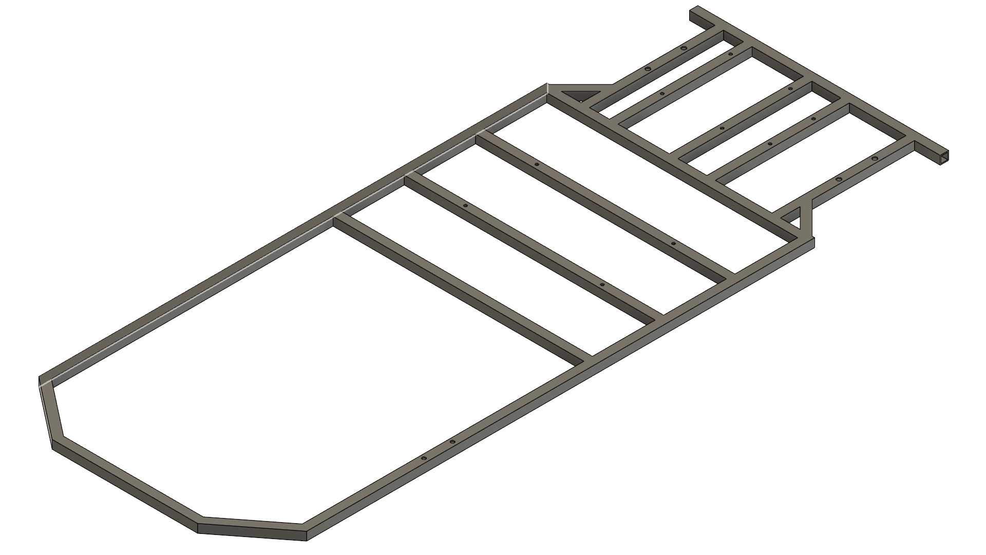
The first few steps of this build are the fabrication of the frame. The frame is made of 3/4" steel square tubing of 13 guage approximately 40ft total length. Going with a bigger or smaller guage is fine but don't go 14 guage or above as it is too thin and will bend under load easily.
List of Tools Required
- MIG or TIG Welding Machine
- Portable Bandsaw or Chopsaw for Metal Cutting
- Angle Grinder
- Drill Press or Hand Drill
List of Materials
- Steel Sqaure Tubing - 17ft
- 1/4" Drill Bit
- 5/16" Drill Bit
First step is to cut each piece of tubing to length using the FRONT FRAME DRAWING (9 pieces total). Next, holes need to be drilled through the tubing using the FRONT FRAME HOLES DRAWING with 1/4" and 5/16" drill bits.
Then, each piece may be welded together using any method you prefer. A common method for welding frames is to fixture each piece on the work surface and clamp or use magnets to fixture pieces together. Proceed to tack weld each tube so it forms into a single body. This allows for the steel to not warp excessively from too much heat. After each piece is tacked, proceed to fully weld each joint.
Before tack welding, make sure to measure each piece twice so it matches the drawing. The angled pieces in the front can be be cut at an angle using a protractor to draw the line and an angle grinder can cut the obsolete angles.
Rear Frame
List of Tools Required
- MIG or TIG Welding Machine
- Portable Bandsaw or Chopsaw for Metal Cutting
- Angle Grinder
- Drill Press or Hand Drill
- 3/8" Drill Bit
- 1/4" Drill Bit
List of Materials
- Steel Sqaure Tubing - 7.5ft
Similarily to the previous step, follow the REAR FRAME DRAWING to cut each piece to length (8 pieces total). Next use a drill with 3/8" and 1/4" drill bits to drill out the holes on the tubing using the REAR FRAME HOLES DRAWING.
Fixture the pieces on the work surface with a clamp or magnets and tack weld each joint and follow with a full weld around. Make sure each piece is square to each other because the rear axle mounts here and must not be croocked.
Under Frame
List of Tools Required
- MIG or TIG Welding Machine
- Portable Bandsaw or Chopsaw for Metal Cutting
- Angle Grinder
- Drill Press or Hand Drill
- 5/16" Drill Bit
List of Materials
- Steel Sqaure Tubing - 7ft
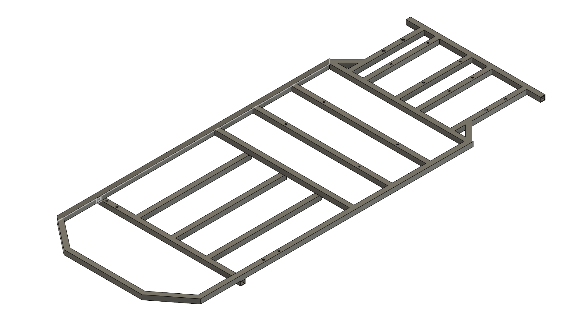
Similarily to the previous step, follow the UNDER FRAME DRAWING to cut each piece to length (4 pieces total). Remember, these pieces go underneath the frame so use the dimensions on the drawing. Next, drill out two 5/16" holes on the single tube piece.
Fixture the pieces on the work surface with a clamp or magnets and tack weld each joint and follow with a full weld around.
Downloads
Seat Frame
List of Tools Required
- MIG or TIG Welding Machine
- Portable Bandsaw or Chopsaw for Metal Cutting
- Angle Grinder
- Drill Press or Hand Drill
- 1/4" Drill Bit
List of Materials
- Steel Sqaure Tubing - 7ft
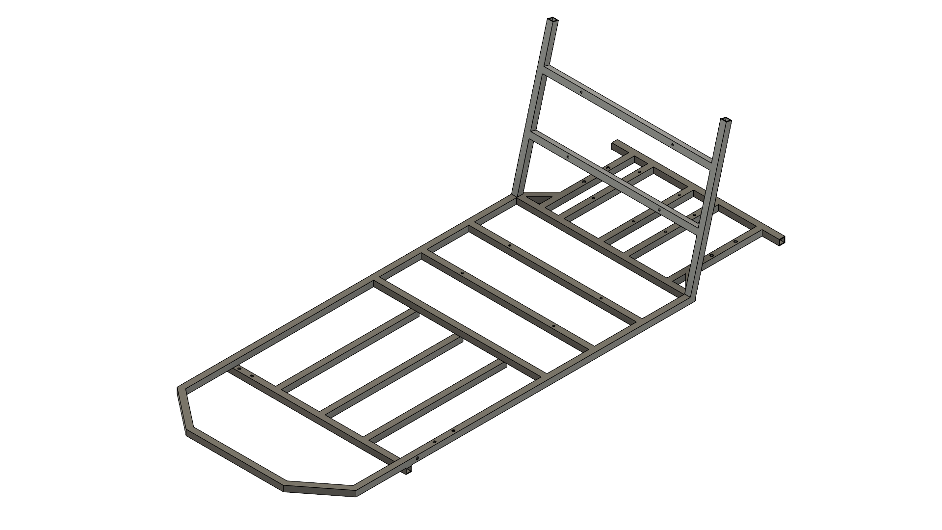
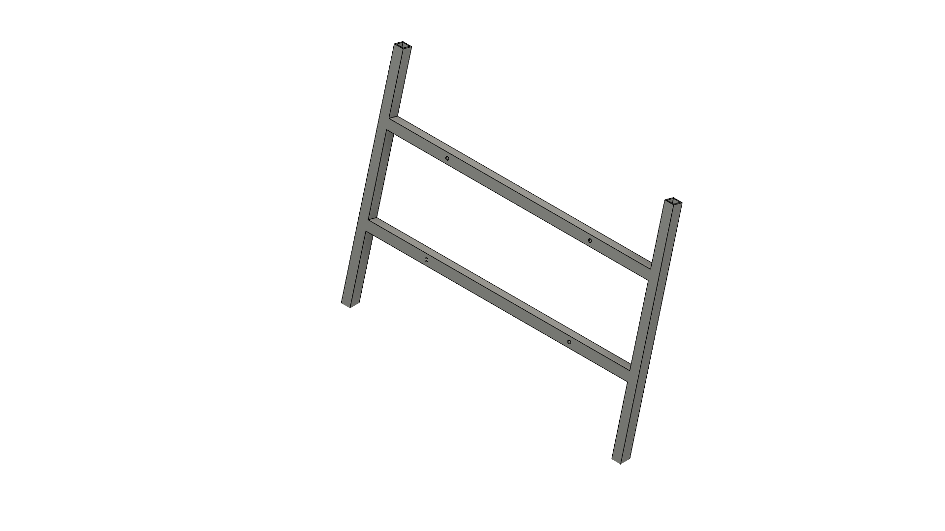
Similarily to the previous step, follow the SEAT FRAME DRAWING to cut each piece to length (4 pieces total). Next, drill out four 1/4" holes on the two pieces of tubing. The two shorter pieces will have the bottom face chamfered at 75 degrees which can be be grinded to the correct angle.
It's a good idea to weld the four pieces together first before welding it directly to the frame. Fixture the four pieces on a work surface with a clamp or magnets and tack weld each joint. Then move the seat frame to the main frame as shown in the drawing. The seat is offset 15 degrees from being perpendiuclar to the frame. Use a digital protractor to adjust the and tack weld each joint and follow with a full weld around after.
Downloads
Motor Plate
List of Materials
- 6061 Aluminum 3/8" thick Sheet
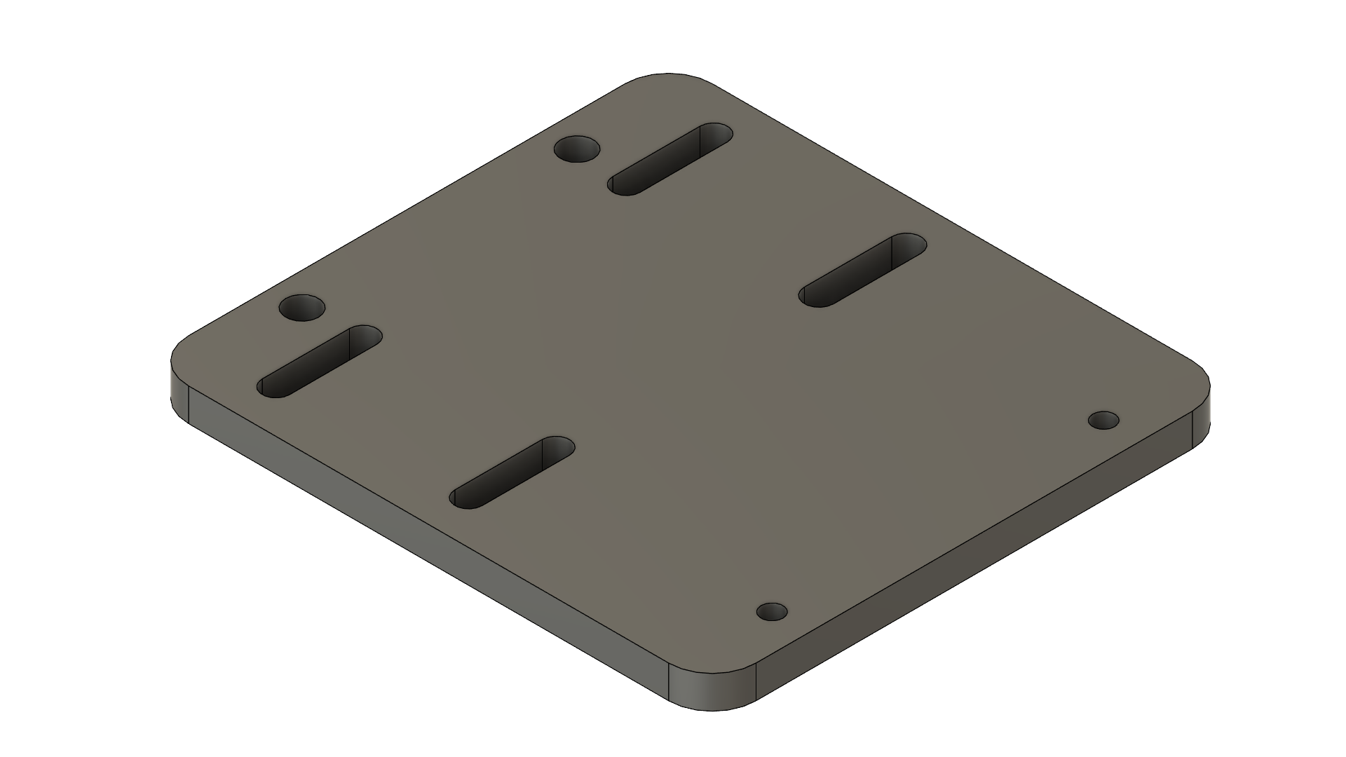
The motor plate serves as a mounting point for the motor to the frame. There are four slots that allows the motor to slide to adjust the tension of the chain. This piece can be machined using a milling machine or can be ordered from SendCutSend or OSHCut. A drawing of the part is attached below with the CAD file included.
Downloads
Brake Caliper Bracket
List of Materials
- A36 HR Steel Angle, 1.25"x1.25"
- (Any steel works, 1" or 1.5" also works but will need to modify dimensions)
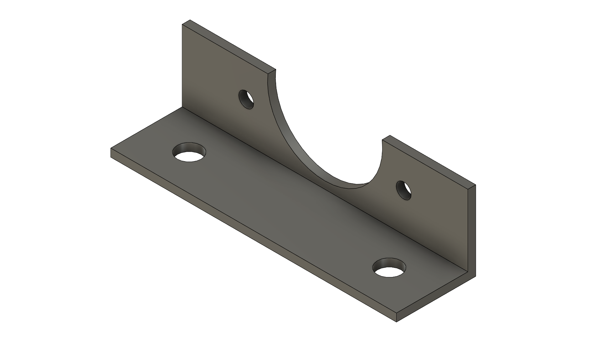
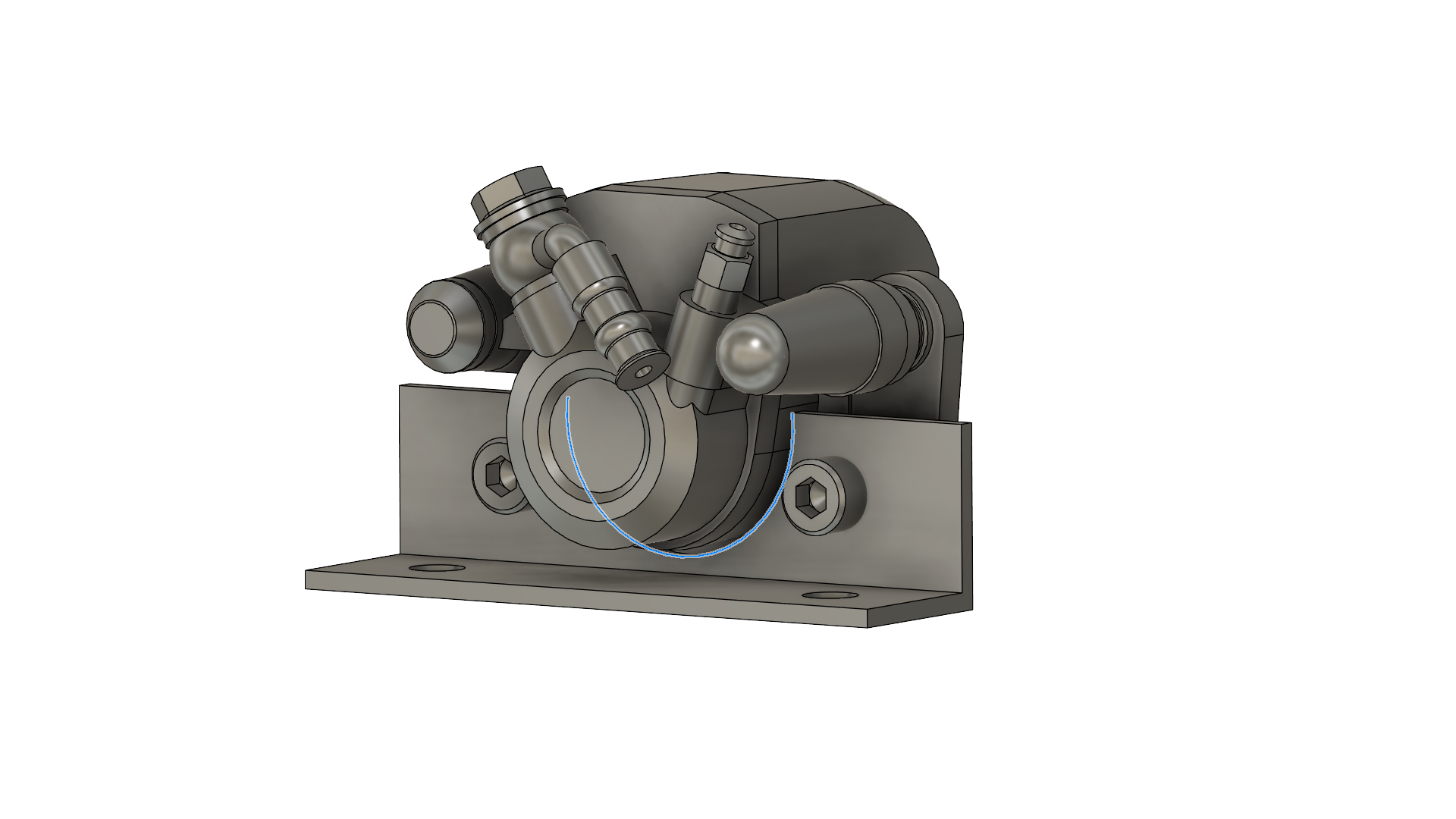
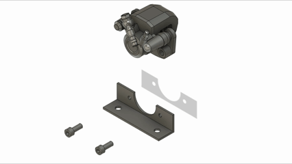
The brake caliper bracket allows to mount the brakes to the rear axle. The part is from a piece of angled iron steel and has four holes and one ciruclar cutout. The 0.236" holes are for 6M bolts but you can use a 1/4" drill bit. The large 1.8" diameter circular cutout is where the caliper piston sits.
There are two ways to cut this; first is using a hole saw, second is using an angle grinder. Both ways work and the diameter doesn't have to be exact, just as long as the caliper piston sits nicely on the bracket.
Downloads
Rear Axle Mounting
List of Tools Required
- 7/16 Socket Wrench
List of Materials
- 29" Rear Axle
- [2] Pillow Block Bearing
- Sprocket
- Disc Brake
- Motor Plate
- Brake Caliper Bracket
- [4] 3/8"-16, 2" Hex Bolts
- [4] 3/8"-16 Lock Nut
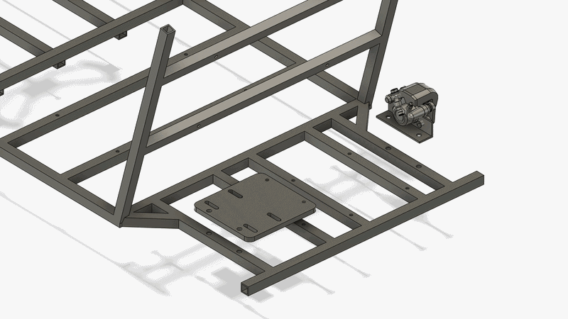
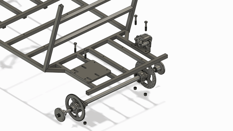
The rear axle is mounted using the two pillow block bearings included in the kit with four 3/8" bolts. First grab the motor plate and brake caliper bracket and place them on top of their dedicated locations of the frame.
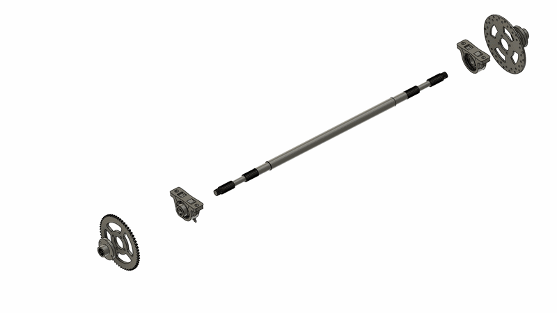
Insert the two pillow block bearings on each end of the axle and slide it through all the way. You may also slide in the sprocket and disc brake. Then, locate the four hole locations on the frame and lineup the the bearings with the frame holes. Use four 3/8" bolts to secure the axle on the frame whoch also pass through and secure the motor plate and brake caliper bracket as seen on the animation.
Motor Assembly
List of Tools Required
- 1/2" Socket Wrench
- Chain Break Tool (Optional)
List of Materials
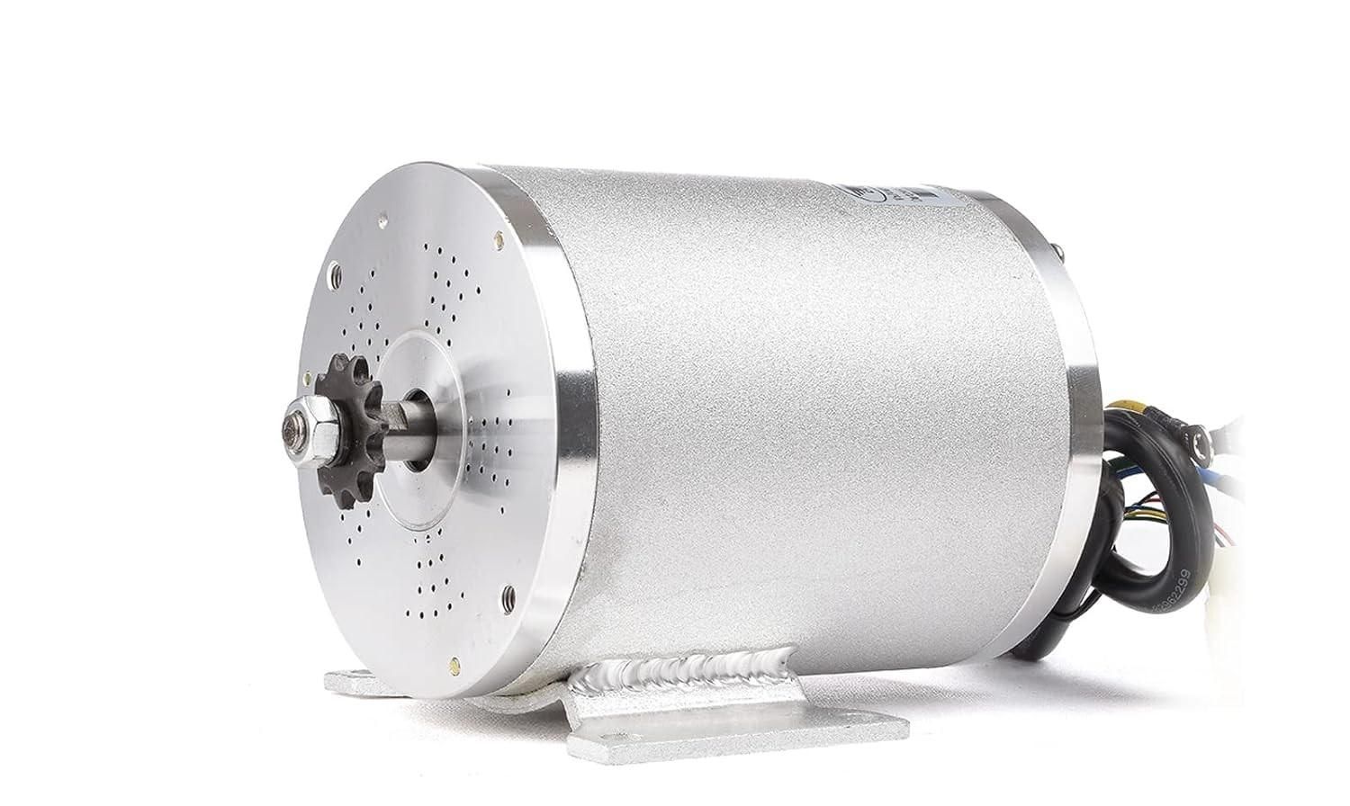
- Brushless Motor
- [4] 5/16"-18, 1" Hex Bolt
- [4] 5/16"-18 Nut
- [2] 1/4"-20, 1.5" Hext Bolt
- [2] 1/4"-20 Nut
- 5/16" Washers (Optional)
- 7/8" ID Pipe (Optional)
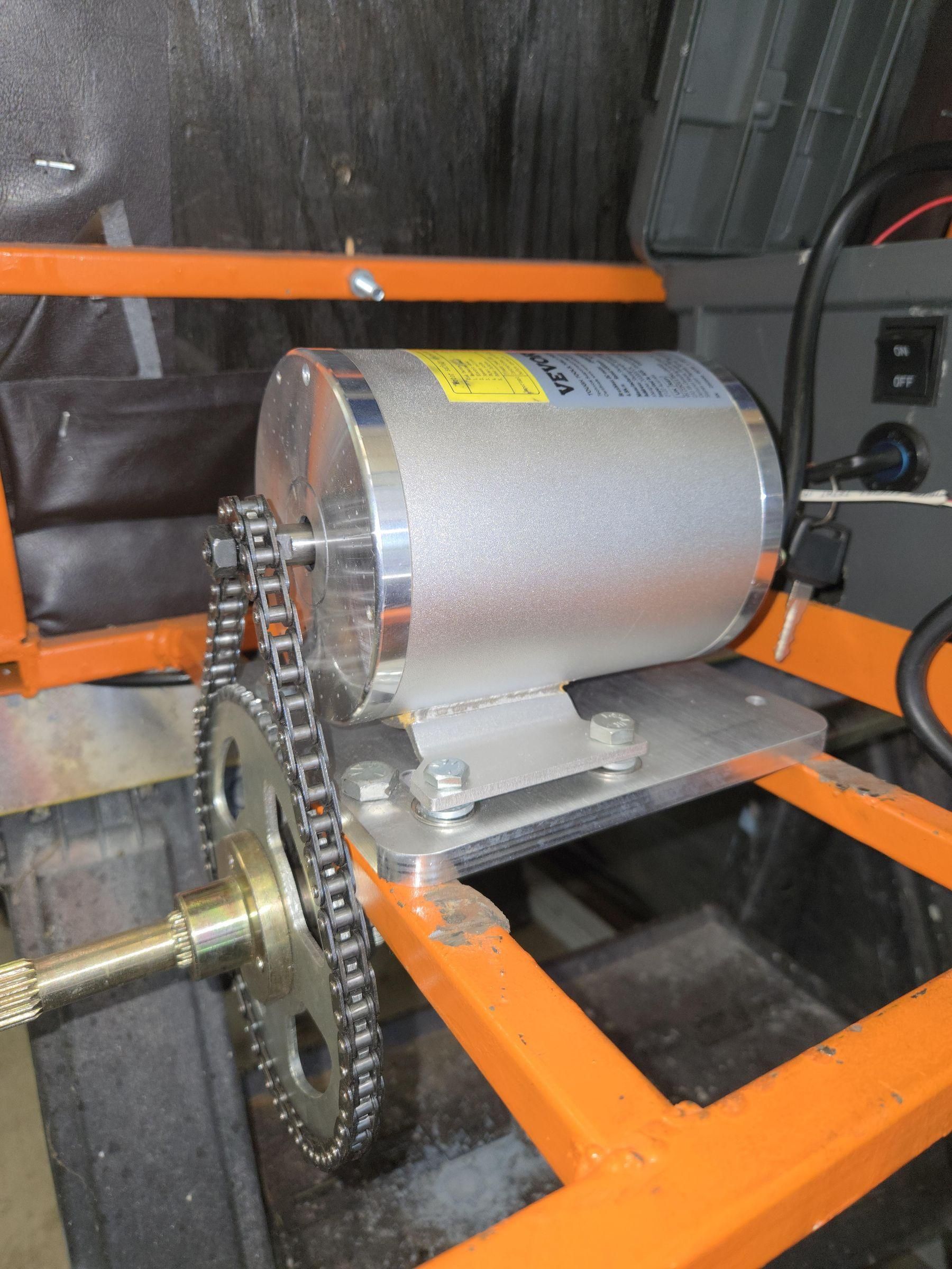
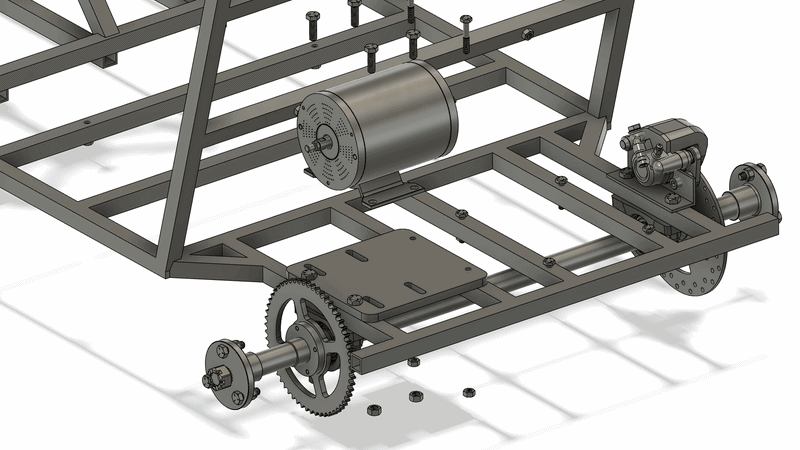
Mount the motor to the Motor Plate slots using 4x 5/16" bolts and 2x 1/4" bolts. Don't tighten the 5/16" bolts yet. Using a flat ruler, check that the motor sprocket and axle sprocket lineup and are parallel to each other. If the sprockets don't lineup, you may add spacers in between the axle sprocket and bearing block using 7/8" ID pipe.
Next, grab the chain included with the kit and wrap it around both sprockets. The chain will need to be shortened so mark the location of the link that sets the correct length. To shorten the chain, you will need to remove the pins which hold the links together. There is a special tool used to break links or you may use a hammer and nail to push the pins out. Refer to the videos below on how to shorten the chain.
Once the chian is installed, it needs to be tensioned properly. To tension the chain slide the motor across the direction of the slots. This will push the ceneter axis of the motor shaft and axle away putting more tension on the chain. You want enough tension so you can flex the chain with a single finger. Too much tension will cause fatigue and break the links apart. Once the correct tension is set, tighten the four 5/16" bolts.
Without tool: Break A Roller Chain Without Power Tools or Chain Break - Mini Bike, Kart, ATV
With tool: How to Break Roller Chain & Add Master Links
https://a.co/d/0hhEXF1y
Brake Caliper Mount
List of Tools Required
- 5mm Allen Key
- Metal Cutting Saw (Optional)
List of Materials
- [2] 6M, 12mm Socket Head Screw
- 7/8" ID, 1" OD Pipe (Optional)
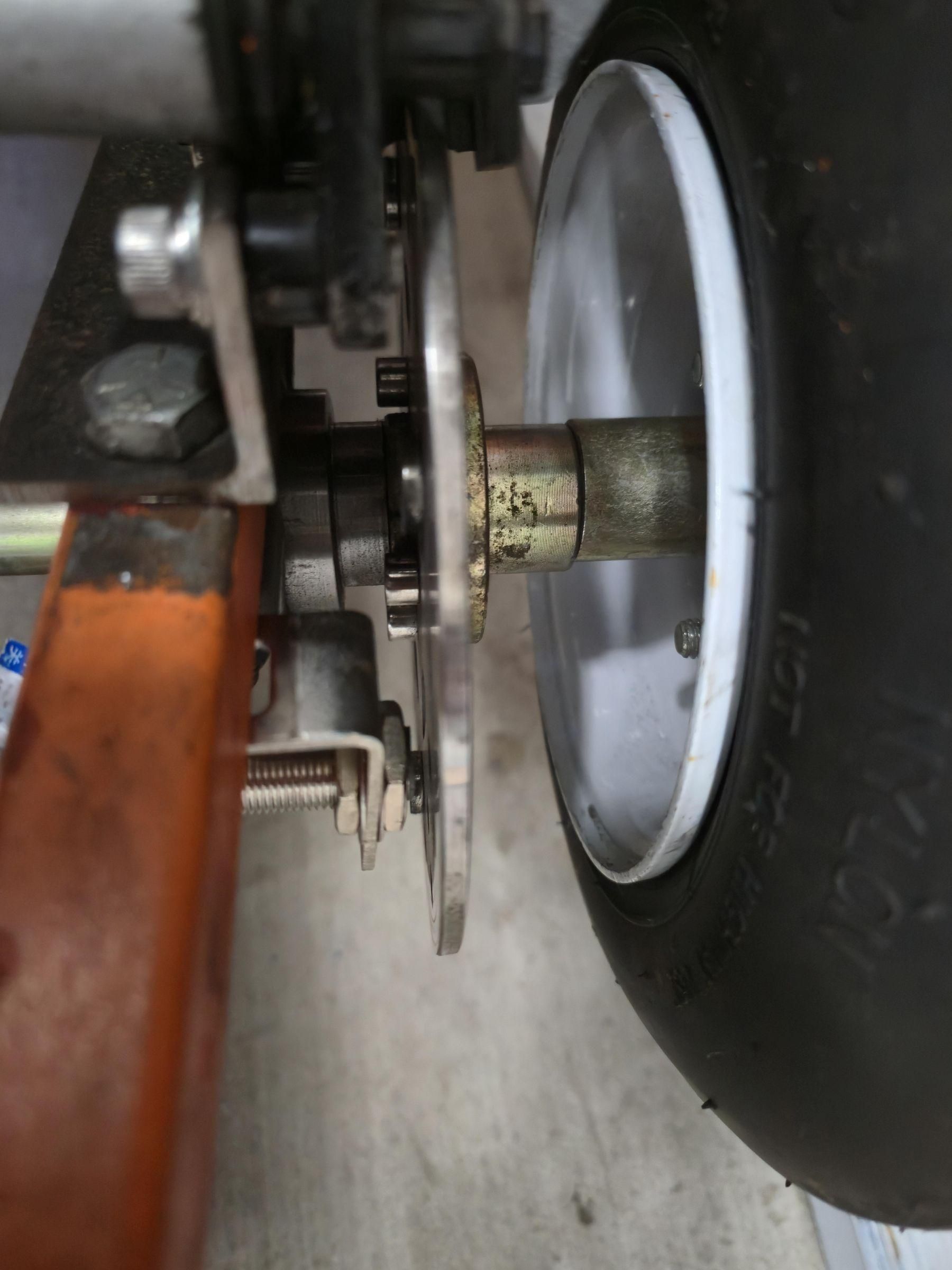
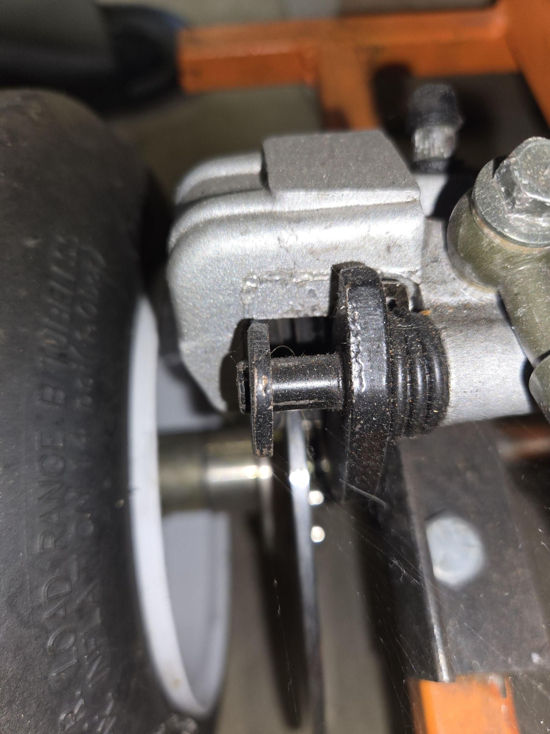
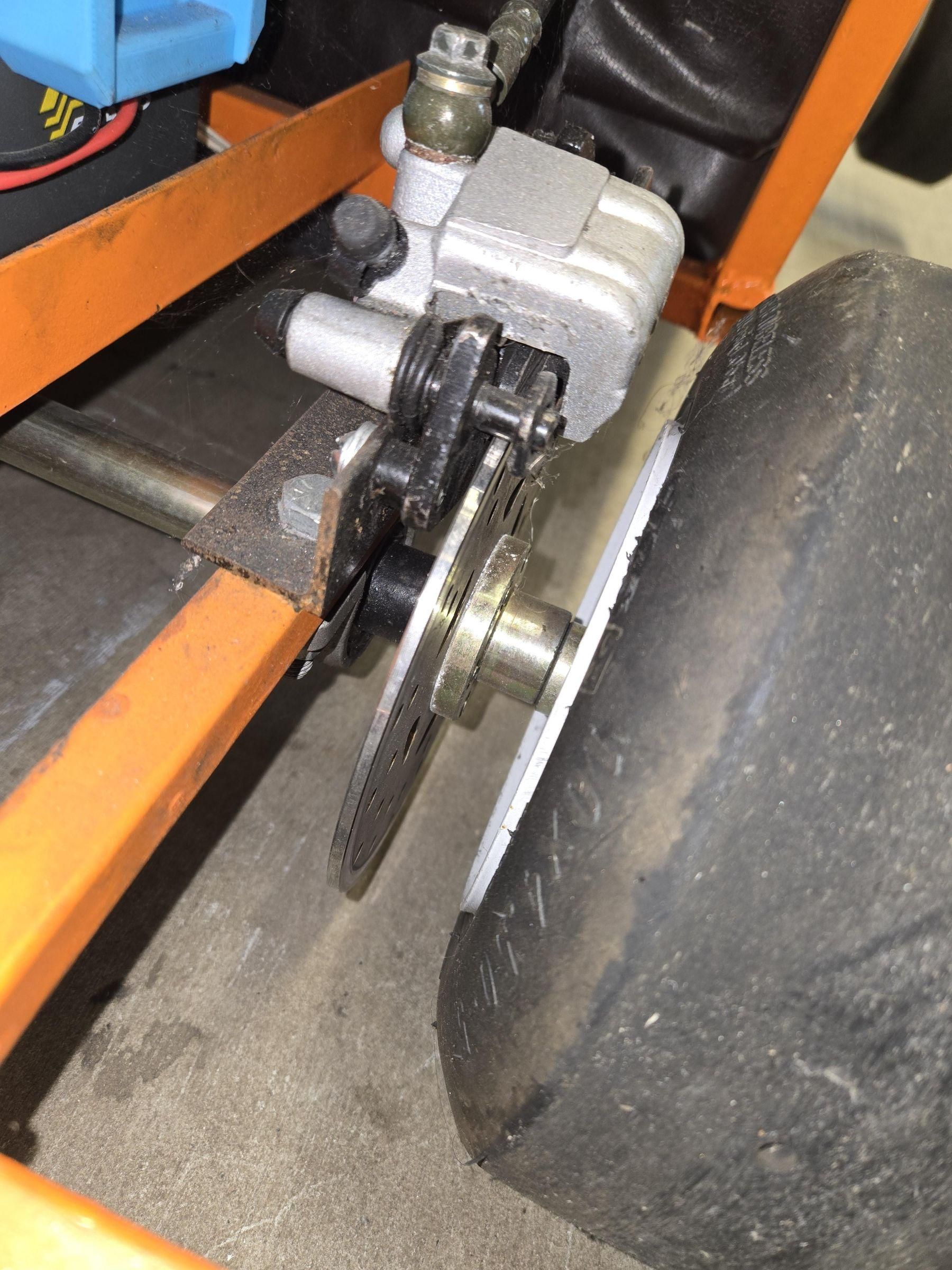
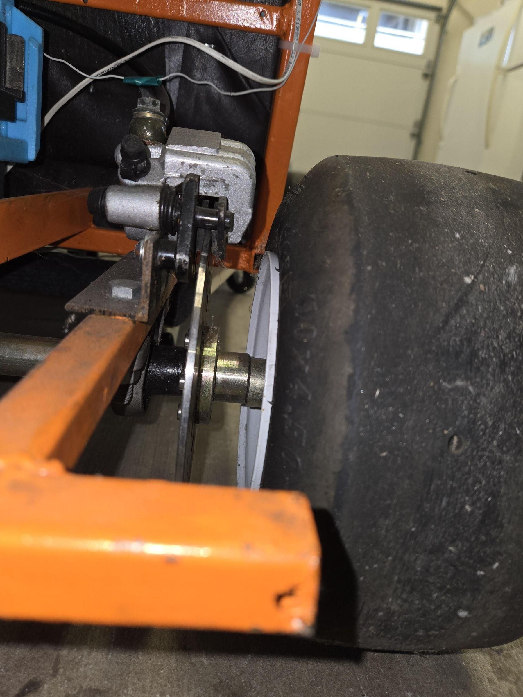
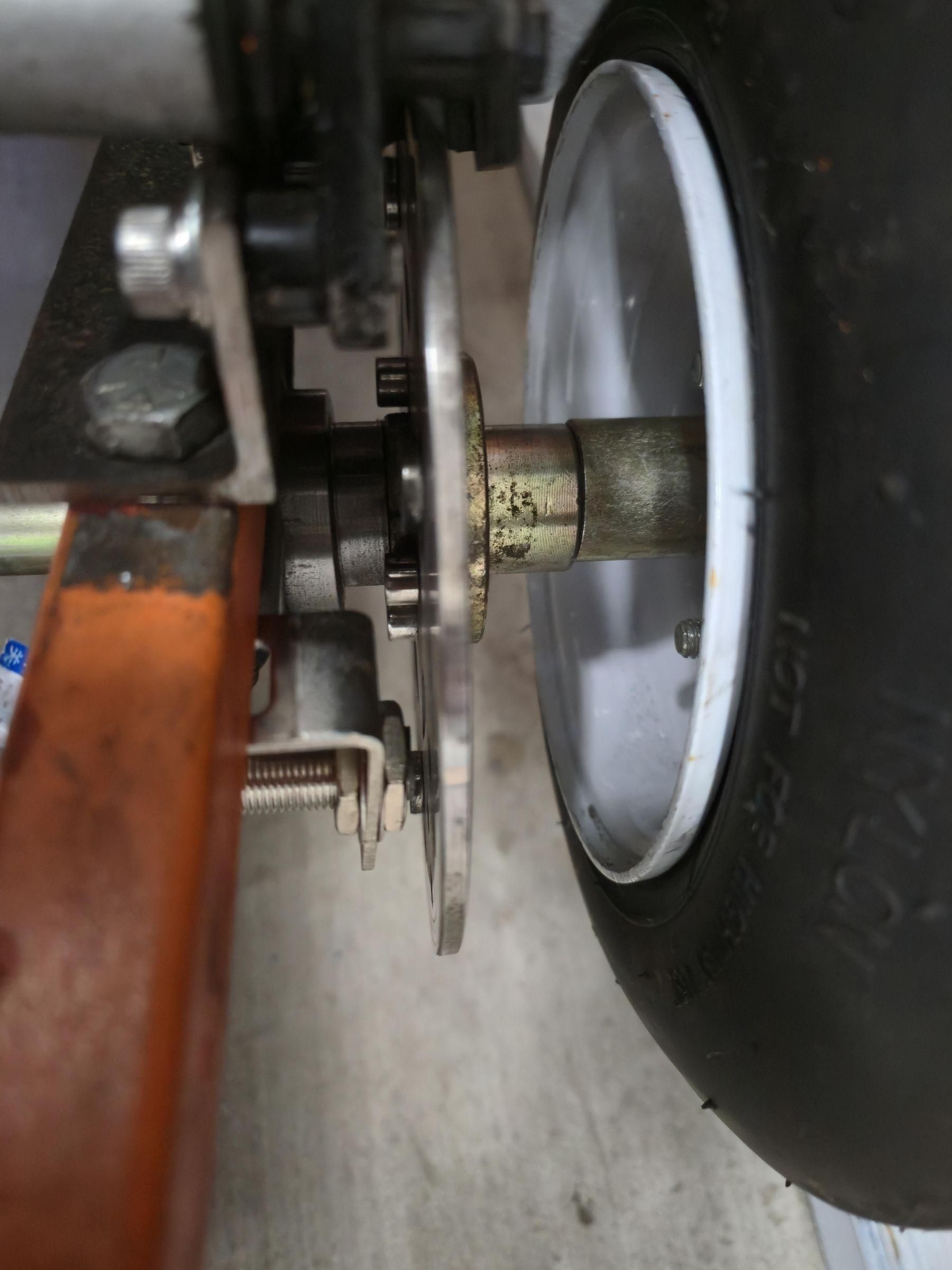
The brake caliper need to be mounted on the already in place bracket. Use two M6 screws to secure the bracket in place. Make sure the disc brake is already in place and place the caliper above the disc. Check the brake pads to see if the disc brake lands in between.
A spacer may be need to adjust the position of the disc brake so it lands in between the brake pads. Measure the bad in between the disc brake and bearing block and use a 7/8" ID pipe to cut it to the correct size.
Steering Shaft
List of Tools Required
- MIG or TIG Welding Machine
- Portable Bandsaw or Chopsaw for Metal Cutting
- Angle Grinder
- Drill Press or Hand Drill
- 5/15" Drill Bit
- 1/4" Drill Bit
- Grinder or Sander
List of Materials
- 5/8" A36 HR Steel Rod, 24" long
- 1.5" x 1/8" A36 HR Flatbar Steel, 4.5" long
- 1.25" x 1/8" A36 HR Flatbar Steel, 3" long
- 2.5" Diameter Washer, 5/8" Bore
- (any steel is fine, wahser diameter can be bigger but not smaller with any thickness)
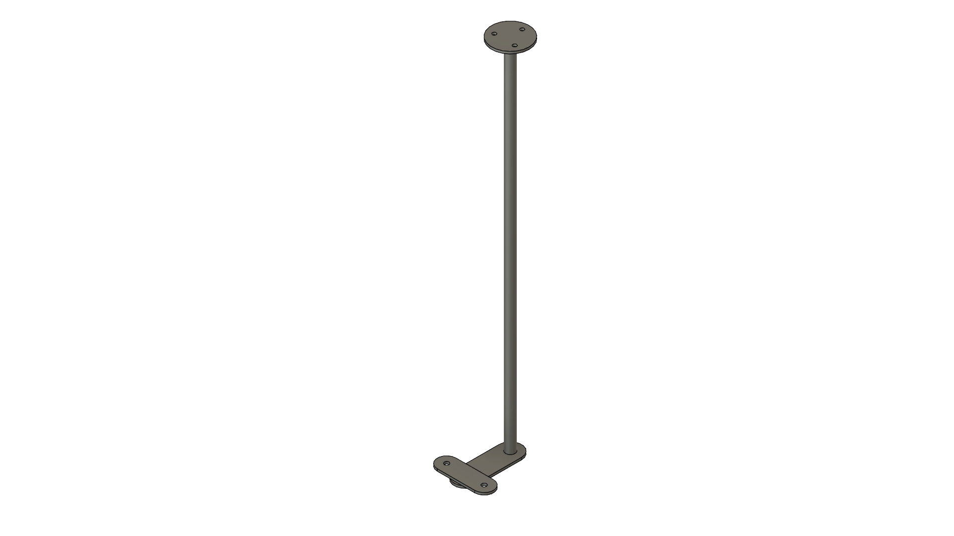
The steering shaft is the cylindrical piece that transfers the force to steer the wheels. Begin by cutting the 5/8" round steel bar to 24". Then, follow the STEERING COLUMN SHAFT ARM DRAWING to fabrciate it using 1.5" and 1.25" steel flatbar. Drill two 5/16" holes on the 1.25" piece and one 5/8" hole on the 1.5" piece. You can round the corners with a grinder or sander. Weld the two pieces together following the drawing.
Slide the arm piece you just welded to the shaft so it is flushed with one end of the rod. Weld all around the shaft so the holes it slid through is no longer visible.
Drill three 1/4" holes through the 2.5" washer in a 1.575" diameter pattern following the STEERING SHAFT DRAWING. Set the washer aside for now.
Steering Bushing
List of Tools Required
- Angle Grinder or Dremel
- Sanding/wire brush
- Socket Wrench
List of Materials
- [2] 6M, 12mm Socket Head Screw
- 7/8" ID, 1" OD Pipe (Optional)
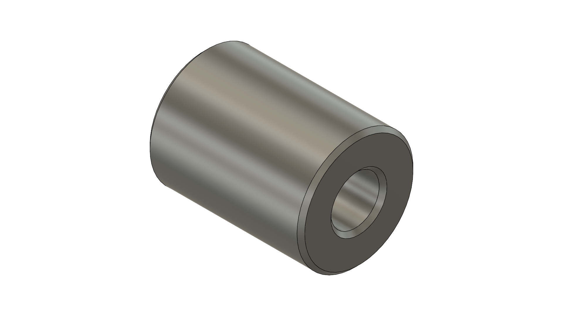
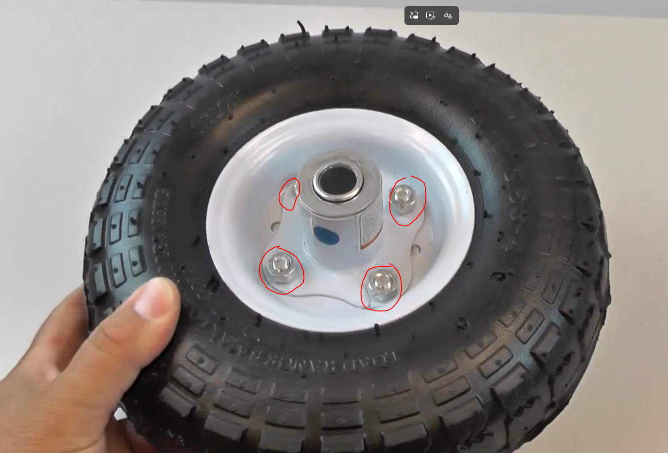
The steering bushings is where the steering cloumn shafts rests and allows for free rotation. The bushings are scrapped out of Harbor Freight 10in wheels mainly because they are extremely cheap. Begin by loosening the four bolts that hold the bushing to the rim. Using an angle grinder or Dremel, cut out the flange so you are left with a cylinder only. Remove all the paint with a sanding/wire disc or by hand with a wire brush. Two bushings are needed so repeat this step with a new wheel.
Steering Column
List of Tools Required
- MIG or TIG Welding Machine
- Clamps and Magnets
- Tape Measure
- Digital Angle Finder
List of Materials
- Steering Column Piece
- Steering Shaft Rod
- [2] Steering Bushings
- 2.5" Washer, 5/8" Bore
- [4] 1.5" Washer, 5/8" Bore
The steering column is the structural part which holds the steering shaft. Begin by cutting a piece of 3/4" square tubing using the COLUMN PIECE DRAWING. The top features a 3/4" radius which can be cut using an angle grinder or Dremel. The accuracy of this curvature is not important so just try to get it close to the drawing. The bottom features a square cutout which can be cut with a angle grinder or Dremel and finished of with a file.
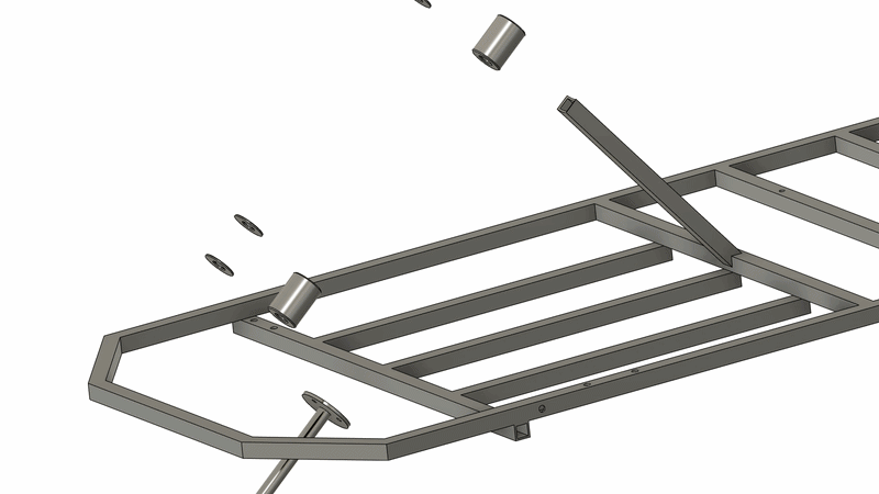
Use the STEERING COLUMN DRAWING to fixture the two Steering Bushings, Steering Shaft Rod, and Steering Column Piece. Use clamps and magents to hold pieces together so you can tack weld. The Steering Column Piece has the circular cutout on top and is offset at 130 dergrees, use a digital angle finder to adjust the angle.
Grab the Steering Shaft Rod and use the follwoing pattern to slide through the 1.5" diameter washers and Steering Bushings.
Washer<-Bushing<-Washer<-Washer<-Bushing<-Washer
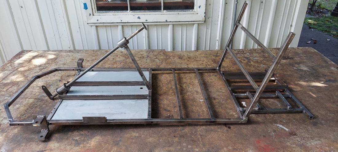
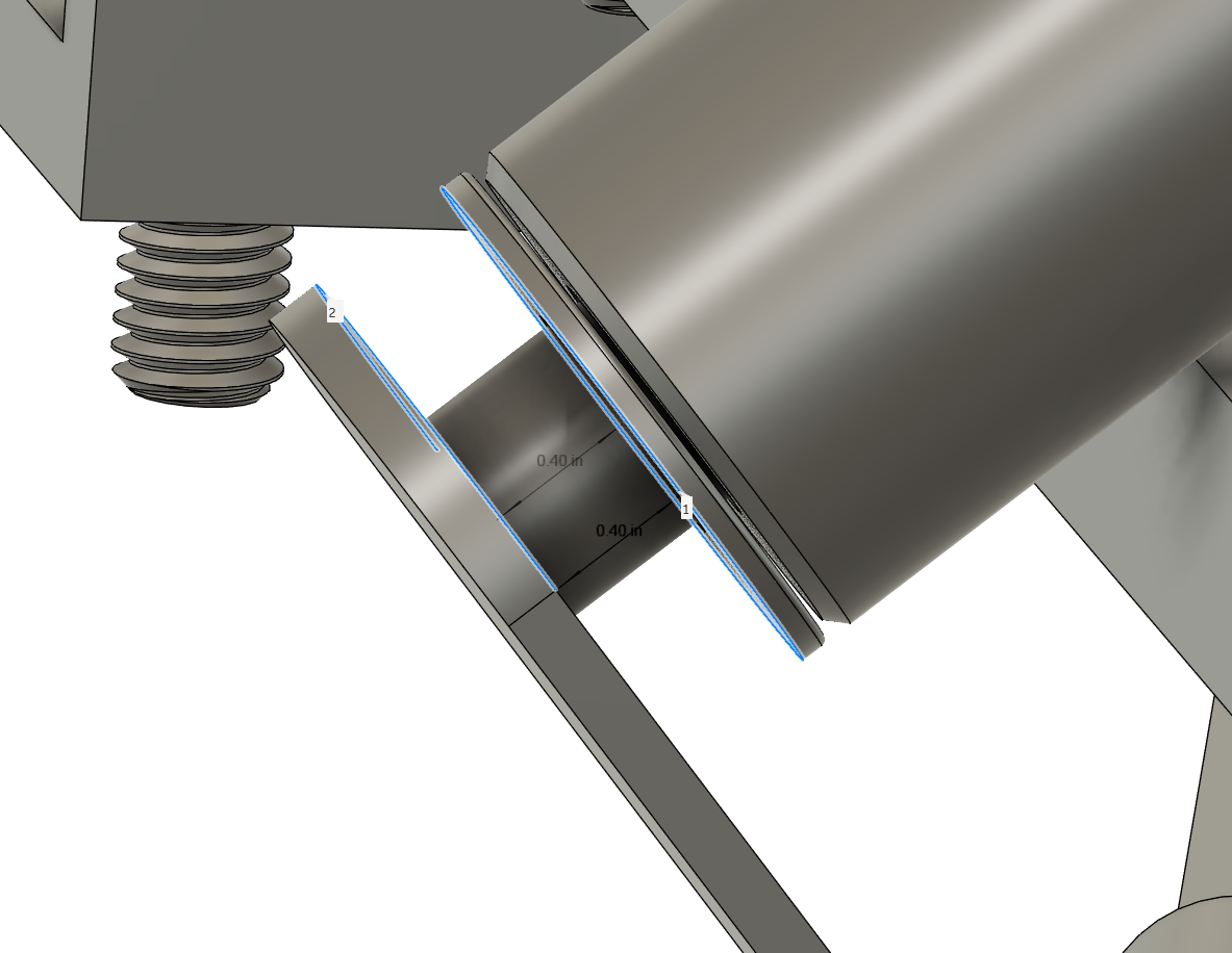
Place the Steering Shaft Rod on top of the frame so the arm that was welded is below the frame. The top bushing should rest on the Steering Column Piece and the bottom piece should rest on the frame tubing near the bottom. The washers should "sanwich" the bushings so each bushing has two washers, one on each face. The Steering Shaft Arm should be set to 0.40" away from the bottom Steering Bushing as shown in the picture.
Once everything is fixtured, tack weld the Steering Column Piece first, then the Steering Bushings followed by the 1.5" washers get welded directly to the rod. This should prevent the rod from sliding up and down.
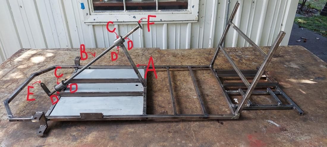
Refer to the diagram shown for reference.
A=Steering Column Piece
B=Steering Rod Shaft
C=Steering Bushings
D=1.5" Washer
E=Arm
F=2.5" Washer
Steering Wheel
List of Tools Required
- 7/16" Socket Wrench
- Drill Press or Hand Drill
- 1/4" Drill Bit
List of Materials
- Steering Wheel
- [3] 1/4"-20 Hext Bolt, 1" long
- [3] 1/4"-20 Nuts
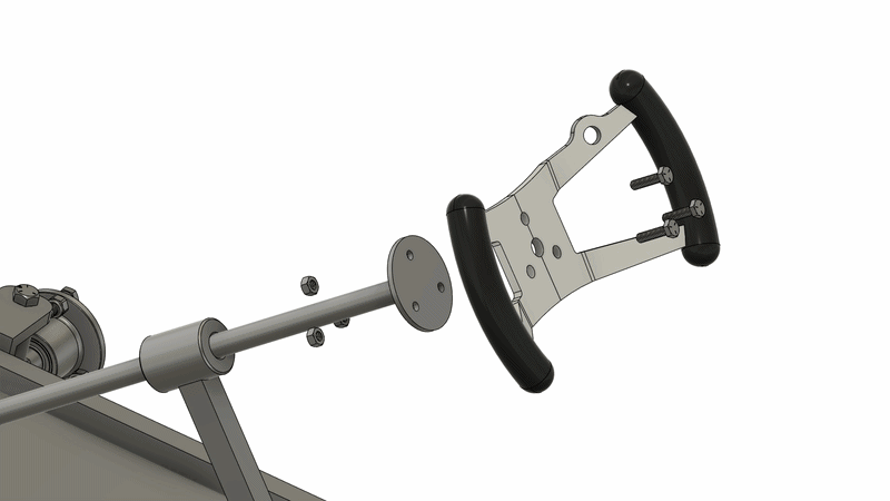
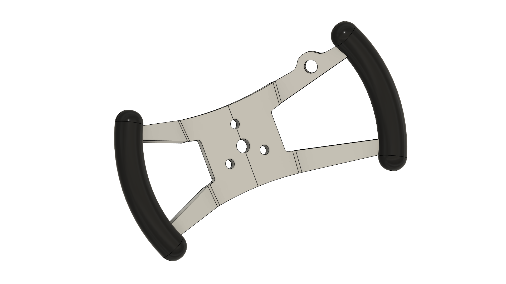
The Steering Wheel is installed on the washer previously welded on the Steering Column Shaft. Use 3x 1/4" bolts to secure the Steering Wheel to the Column Shaft. The holes might be slightly undersize so you may run a 1/4" drill through to make enough clearence for the bolts.
Steering Pivot Bracket
List of Tools Required
- MIG or TIG Welding Machine
- Clamp
- Tape Measure
- Digital Angle Finder
- Drill Press or Hand Drill
- 7/16" Drill Bit
- Grinder or Sander
List of Materials
- 3/8" x 1.5" A36 HR Steel Flat Bar, 2ft long
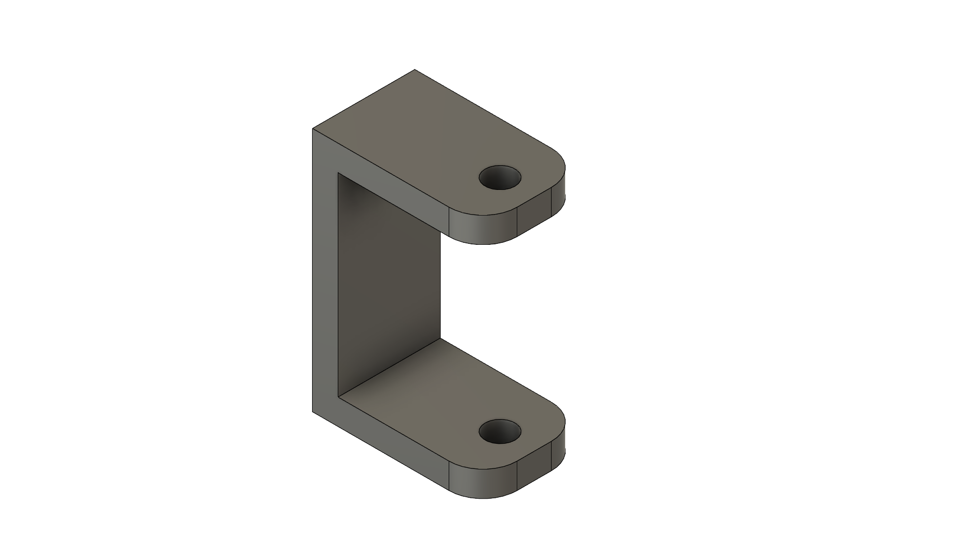
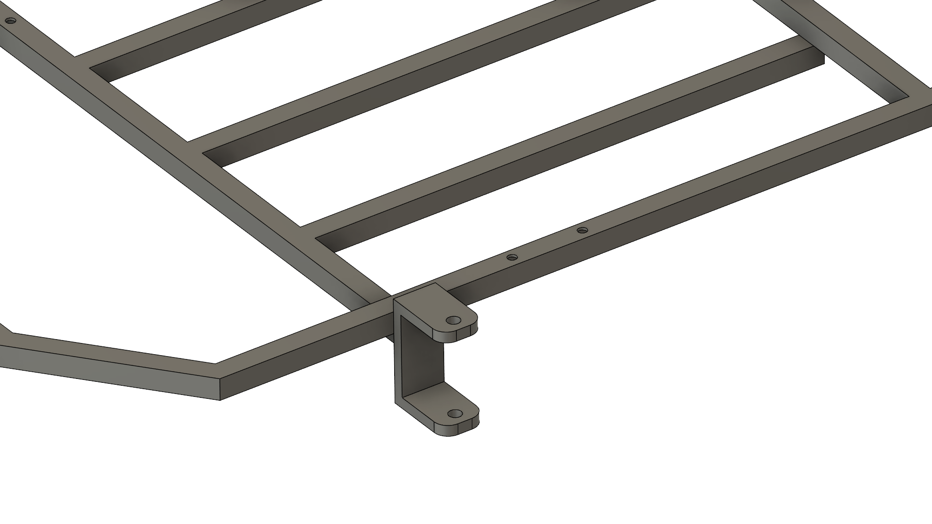
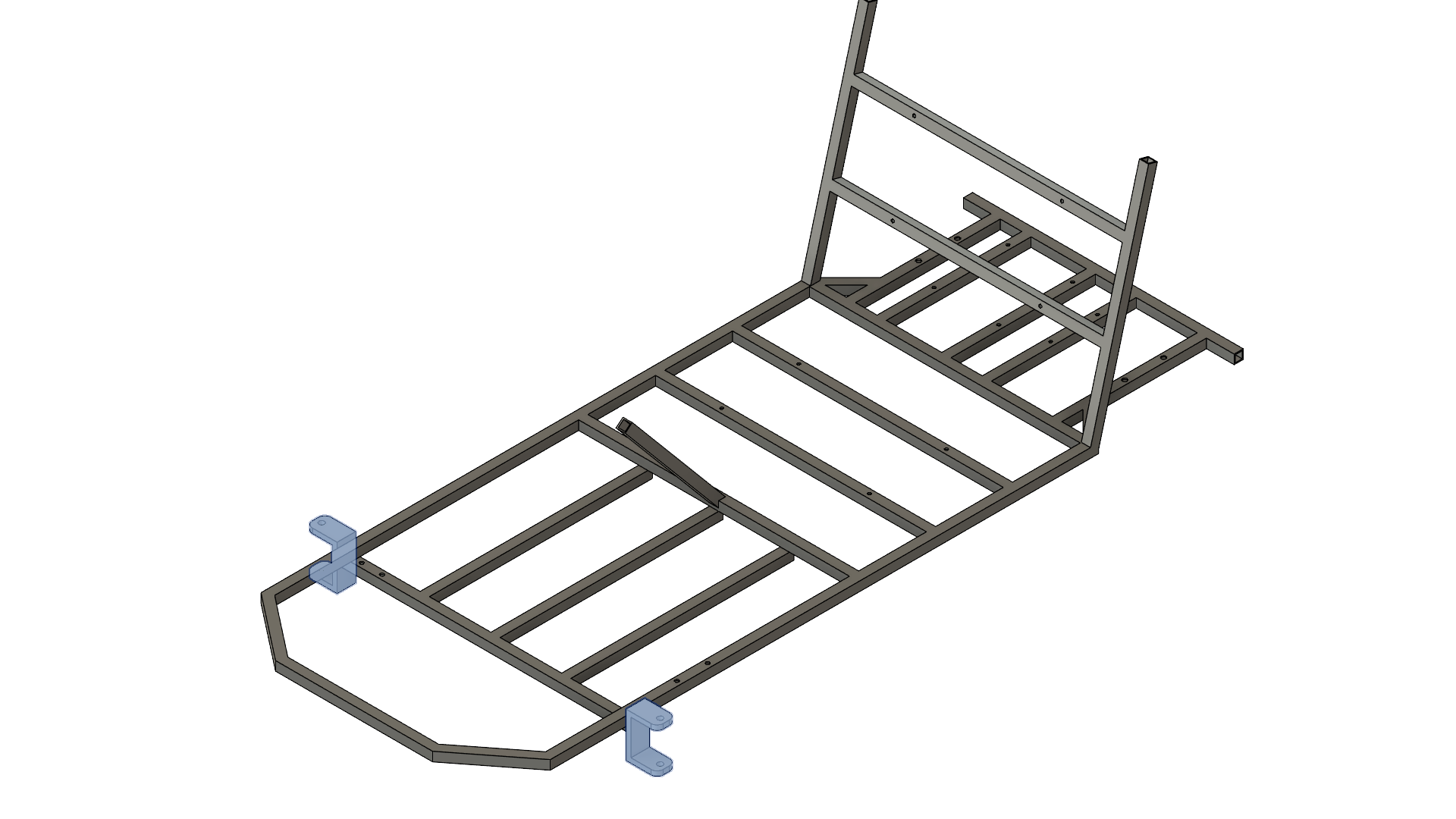
The Steering Pivot Bracket is the structural member that the steering knuckles pivot around. Using 3/8" steel flatbar, follow the STEERING PIVOT BRACKET DRAWING to cut three pieces. Drill a 7/16" hole on each of the smaller pieces. Fixture the pieces so they are square to each other and weld it together. Grind the corners of the smaller pieces to add a fillet as shown.
Next step is to weld the bracket to the frame. Follow the STEERING PIVOT ARM POSITION DRAWING which indicates the position of the bracket relative to the frame. It uses the rear end of the seat as a reference and the front before the angled pieces. Use a digital angle finder to make sure the bracket is vertical to the frame. Clamp the bracket to the frame and weld all around each joint.
Follow the same steps for the other side of the frame as one bracket goes on each side.
Spindles
List of Tools Required
- MIG or TIG Welding Machine
- Magnets
- Calipers
- Digital Angle Finder
- Protractor
- Drill Press or Hand Drill
- 5/16" Drill Bit
- Grinder or Sander
List of Materials
- 7/16" ID, 3/4" OD Steel Pipe
- 5/8" Hex Bolt, 3.5" Long
- 1/8" x 3/4" Steel Flatbar, 1ft long
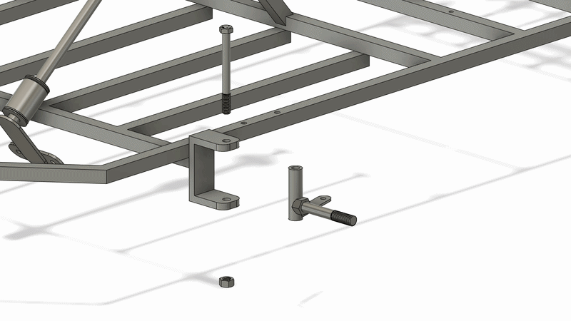
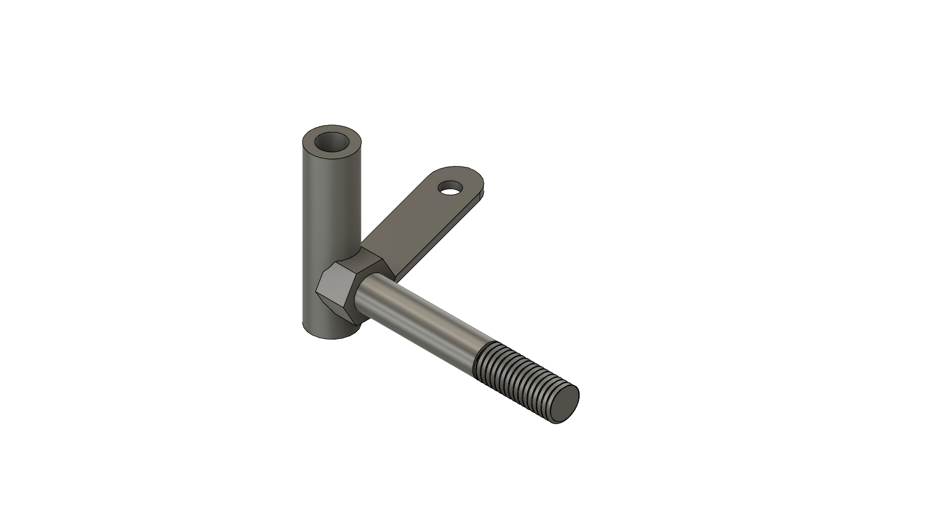
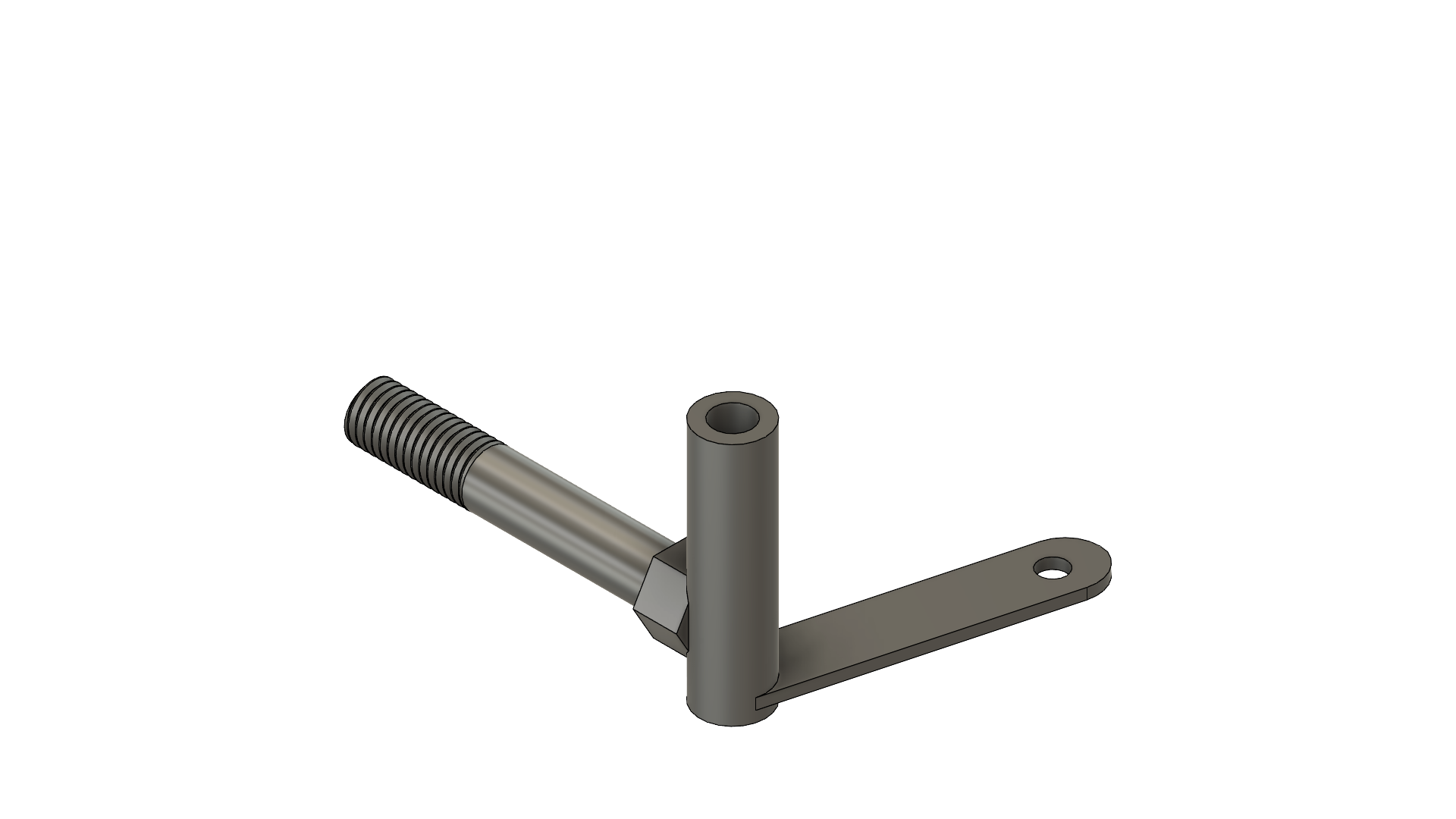
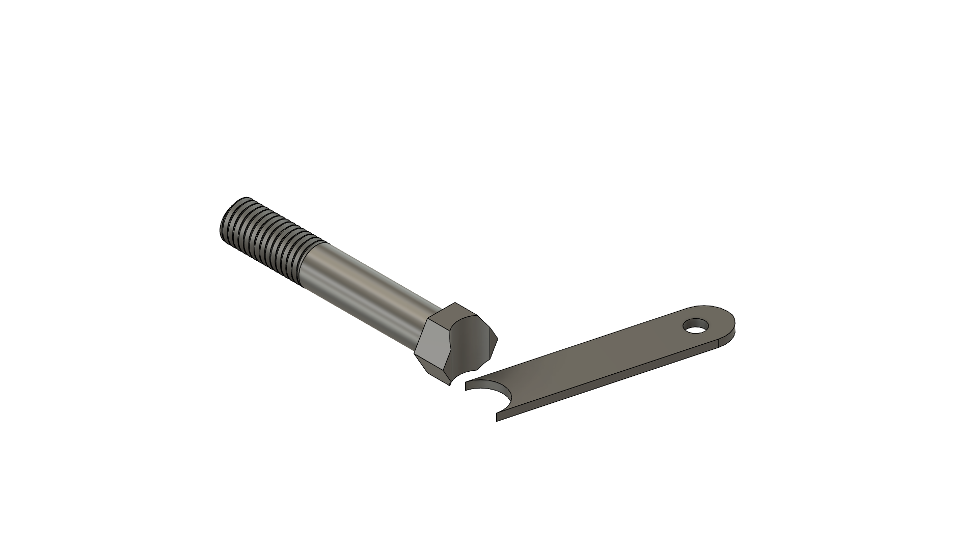
The Spindles are the joints in which the front wheels mount to. This part is slightly complex so take your time with each step below. Refer to the drawings attached when following each step.
- Grab a 7/16" ID pipe and cut it to 2.80" in length
- Grab a 1/8" x 3/4" flatbar steel and cut it to 3.50" in length
- Drill a 5/16" hole on the flatbar that is 3" from one end and centered
- Use an angle grinder to create a circular cutout on the other end of the flatbar so the pipe fits flushed, doesn't have to be perfect but enough material contacts the pipe
- Grind a fillet on the end with a hole of the flatbar
- Grab a 5/8" bolt and grind a circular cutout on the head of the bolt so the pipe rests on the head easier, doesn't have to much, only a slight grind should be fine.
- Position the pipe vertical on a surface and position the bolt perpendicular to the pipe at about 0.49" from the bolt bottom threads to the table surface, use calipers to measure. Use digital angle finder to make sure bolt is perpendicular. (Use thin metal pieces or 3D print blocks to hold objects at correct heights. Magnets also work very well)
- Tack weld the bolt to the pipe.
- Grab the flatbar and position it 0.125" from the table surface
- Use a protractor to offset the flatbar so it's 105 degrees from the bolt
- Tack weld the flatbar
- Double check each measurement is correct
- Do a full weld around each joint.
There are two spindles, one for each side so follow the same steps as each spindle is the same but mirrored.
Attach the spindles to their brackets as shown using a 7/16" bolt. If the pipe is too long, you may use a grinder to remove so of the length but not too much as the pipe must be constrained between the two faces of the bracket.
Here is an example of welding the spindle. Different type of spindle but same concept.
Linkages
List of Tools Required
- 1/2" Socket Wrench
List of Materials
- [2] 300mm Tie Rod
- [4] 5/16"-18 Hex Bolt, 1.25" Long
- [4] 5/16"-18 Lock Nut
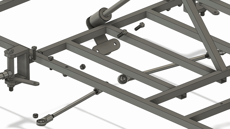
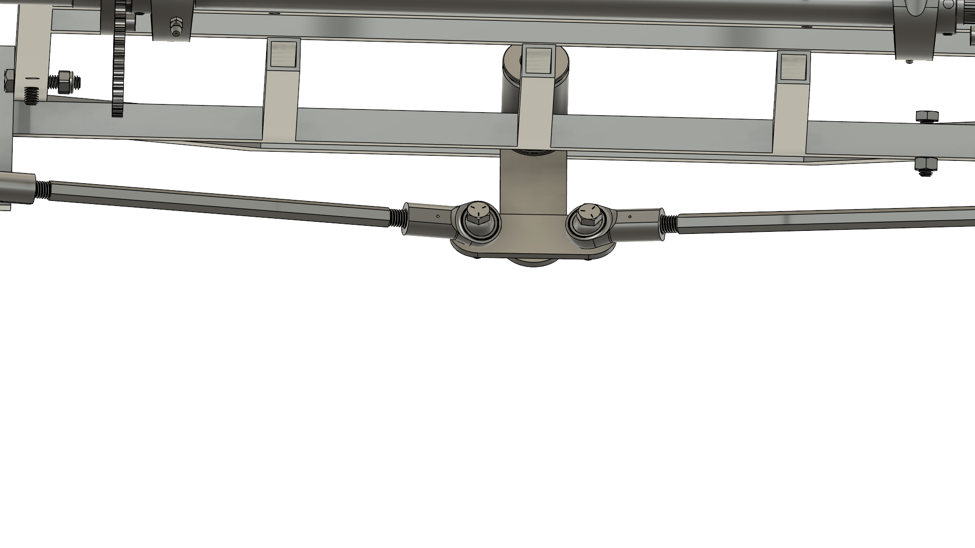
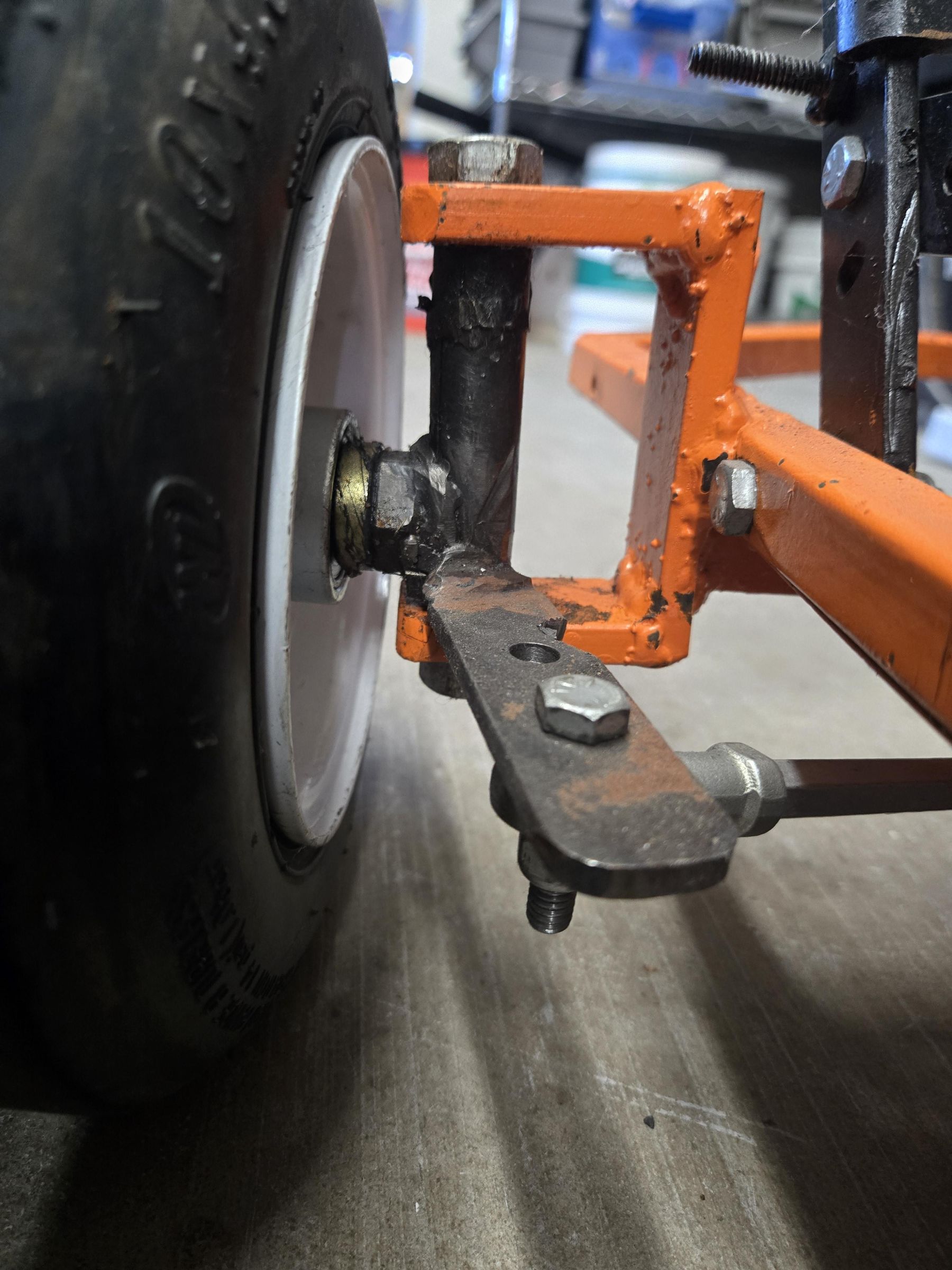
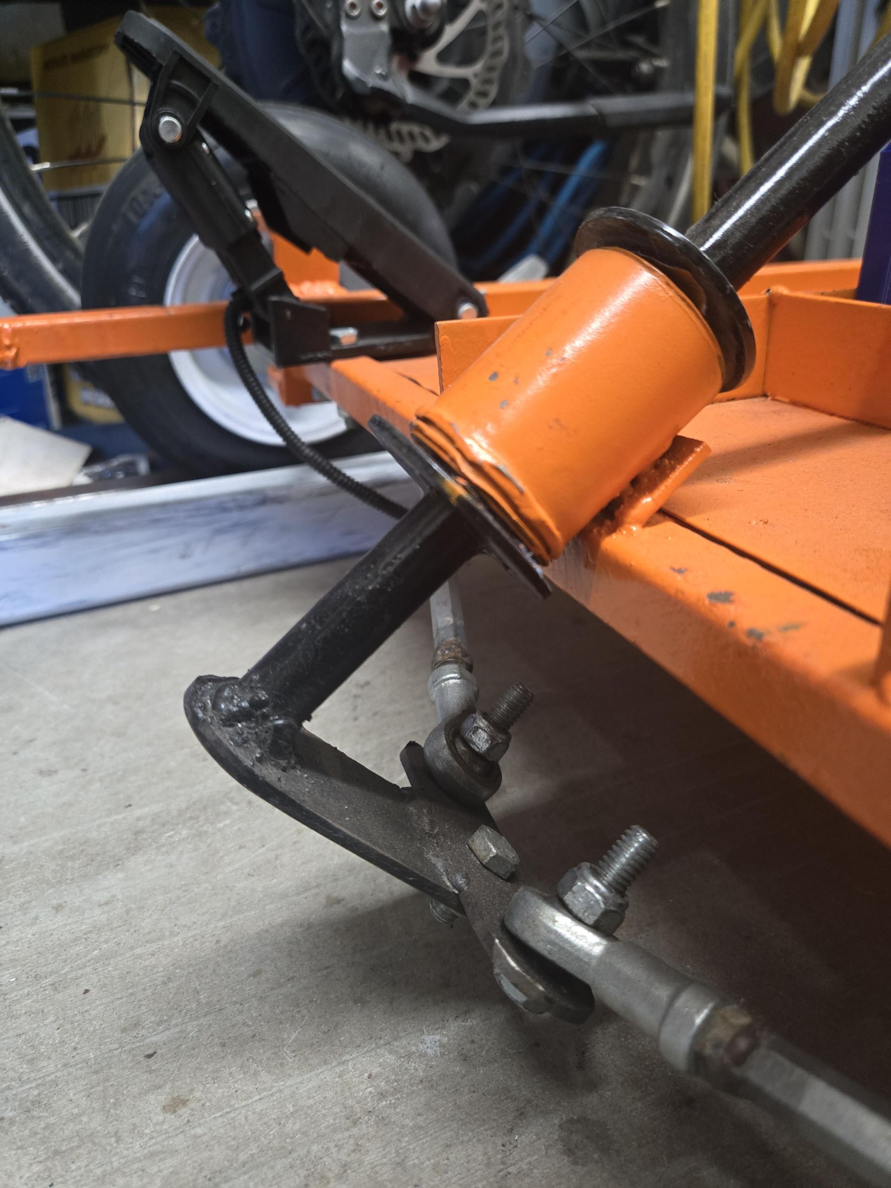
The linkages connect the Steering Shaft to the Spindles. Two threaded rods, one for each side are bolted togther with 5/16" bolts. The rods are threaded on each end allowing for the ball joints to vary in length. Tighten or loosen the ball joints so the holes line up with the Steering Shaft Arm and Spindles. Also, check that the spindle bolts are straight. These ball joints also allow to align the front wheels so they rotate correctly. Don't tighten the lock nuts, this will bind the linkages. Play with the steering wheel while tightening the lock nuts so the linkages move freely without any binding. Refer to the animation for assembly instructions.
This video shows how adjusting tie rods affects wheel alignment
Rear Wheel
List of Tools Required
- 15/16" Socket Wrench
- 1//2" Socket Wrench
- Metal Cutting Saw
List of Materials
- [6] 5/16"-18 Hex Bolt, 1" long
- [6] 5/16"-18 Nut
- 3/4" ID Pipe, 4" long
- [2] Wheel 10in. x 4.5-5in.
- Rear Wheel Hub
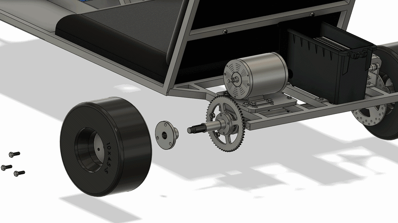
The rear wheel is assembled with 3 5/16" bolts. Insert the Rear Wheel Hub to the back side of the wheel rim. Install the three bolts and tighten them down.
Slide the wheel through the rear axle shaft and tighten it with the M16 nut. Repeat process with the other side.
A 3/4" ID spacer may be needed to sit in between the wheel and sprocket/brake disc. Measure and cut one to sizeso the rear wheels sit flush. Should be approximately 2" long.
Front Wheel
List of Tools Required
- 15/16" Socket Wrench
- 1//2" Socket Wrench
- Metal Cutting Saw
List of Materials
- [6] 5/16"-18 Hex Bolt, 1" long
- [6] 5/16"-18 Nut
- 5/8" ID Pipe, 2" long
- [2] Wheel 10in. x 4.5-5in.
- Front Wheel Hub
The front wheel is assembled in a similar manner as the rear wheels.
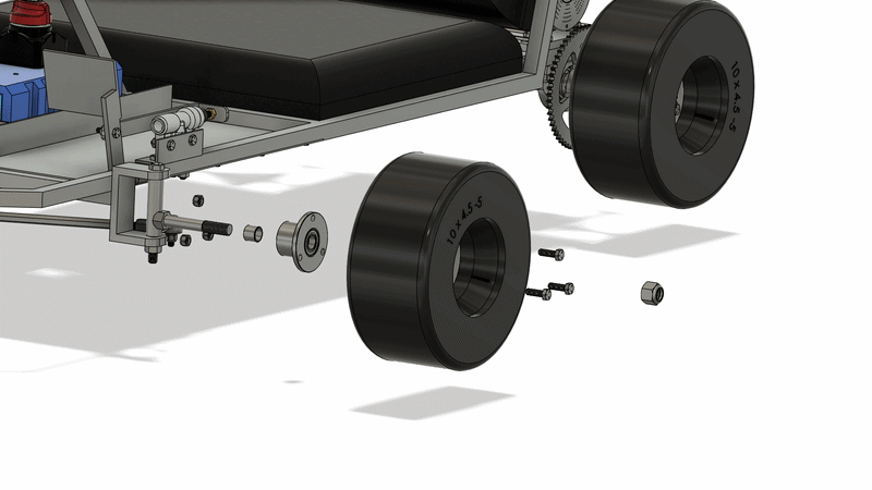
Slide the Front Wheel Hub into the backside of the wheel rim. Insert the 5/16" bolts through and tighten them.
Slide the wheel into the spindle shaft, then tighten the 5/8" lock nut to keep the wheel from sliding. Repeat the process for the other side.
A 5/8" ID spacer may be needed so the front wheel doesn't hit the frame while turning. Measure and cut a piece of pipe to 5/8" in length and install it.
Brake Piston
List of Tools Required
- 1/2" Socket Wrench
- 7/16" Socket Wrench
List of Materials
- 1.25"x1.25" Angled Steel, 4" Long
- [2] 5/16"-18 Hex Bolt, 1" Long
- [2] 5/16"-18 Nut
- [2] 1/4"-20 Hex Bolt, 1" long
- [2] 1/4"-20 Nut
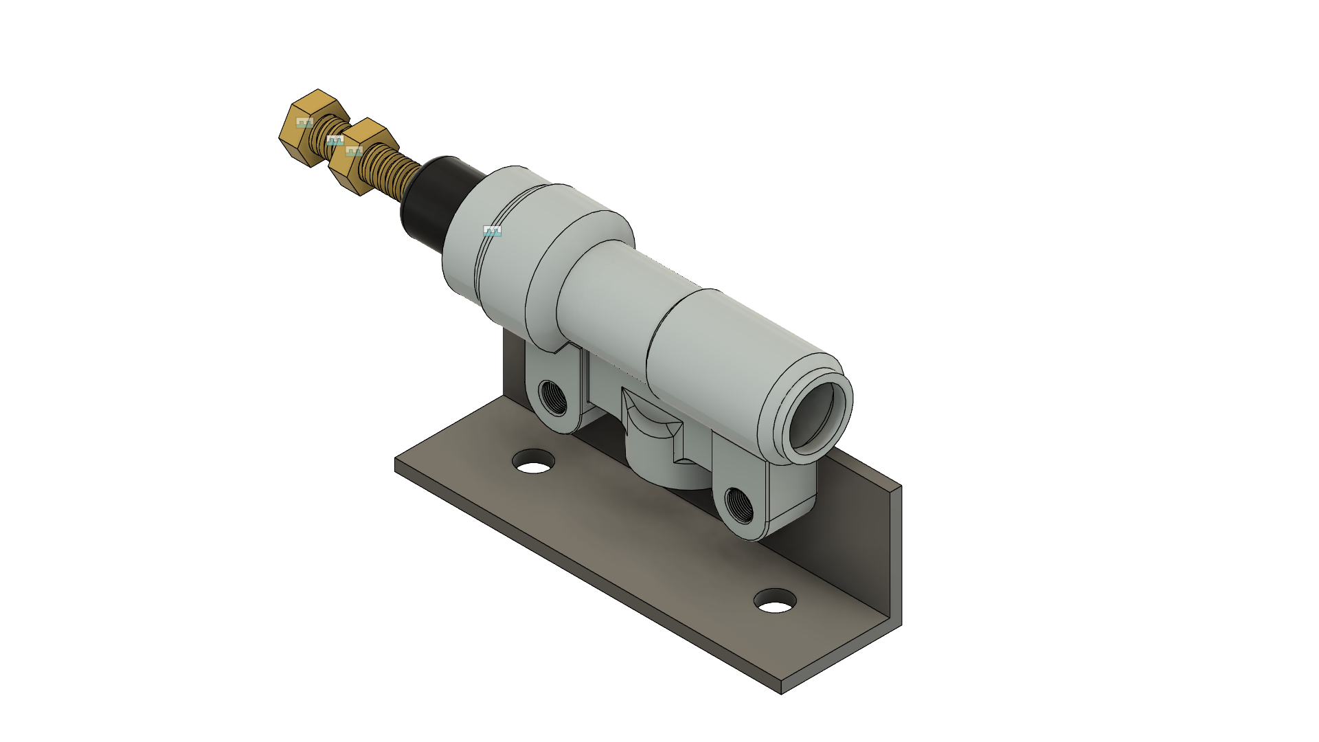
- Brake Piston
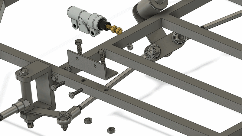
The Brake Piston holds the reservoir of brake fluid. The bracket is made of angled steel with four holes. Use the BRAKE PISTON DRAWING to cut a piece of angled steel and drill four holes.
Mount the bracket to the frame using 2x 5/16" bolts. Then, mount the Brake Piston to the bracket with 2x 1/4" bolts.
Downloads
Brake Pedal
List of Tools Required
- 1/2" Socket Wrench
- 9/16" Socket Wrench
List of Materials
- 1/8" x 1" Flatbar Steel, 5" long
- 1/8" x 3/4" Flatbar Steel, 1ft long
- [2] 5/16"-18 Hex Bolt, 1" Long
- [2] 5/16"-18 Lock Nut
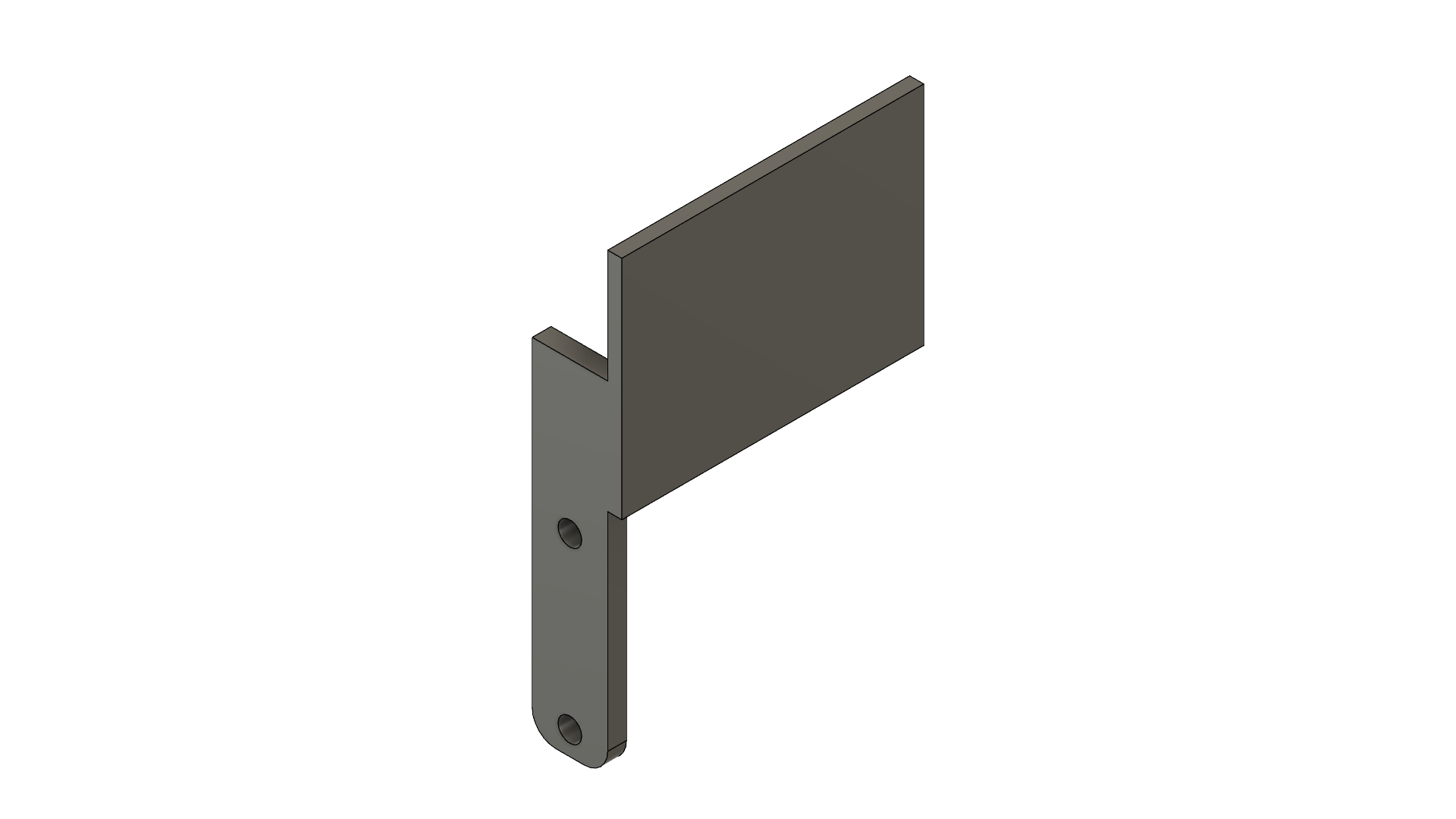
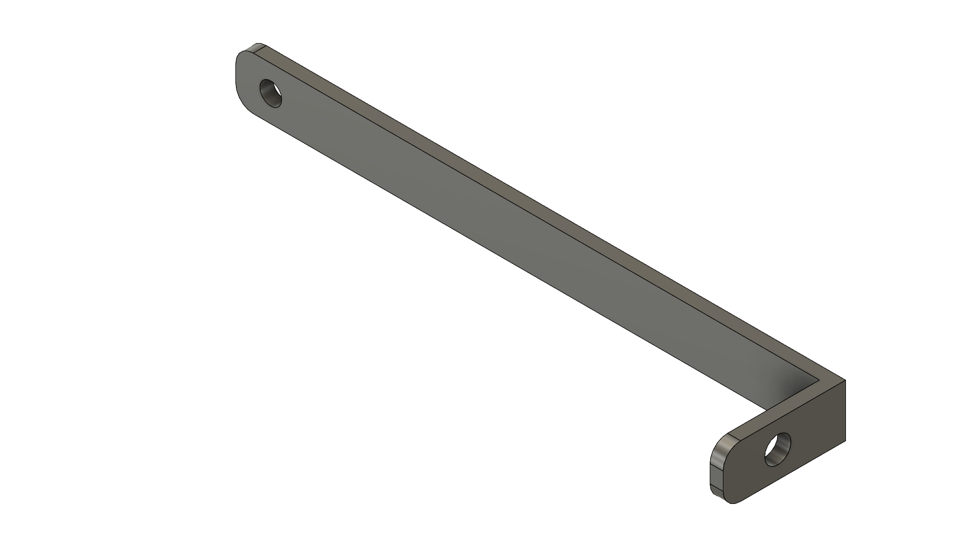
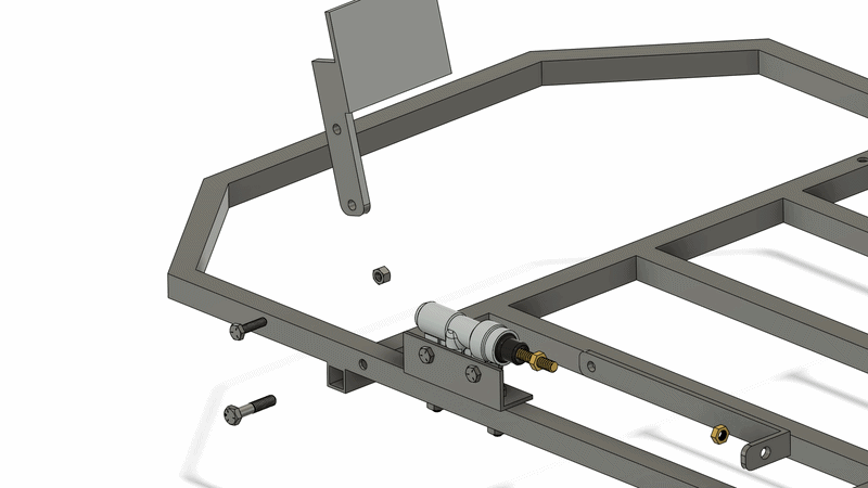
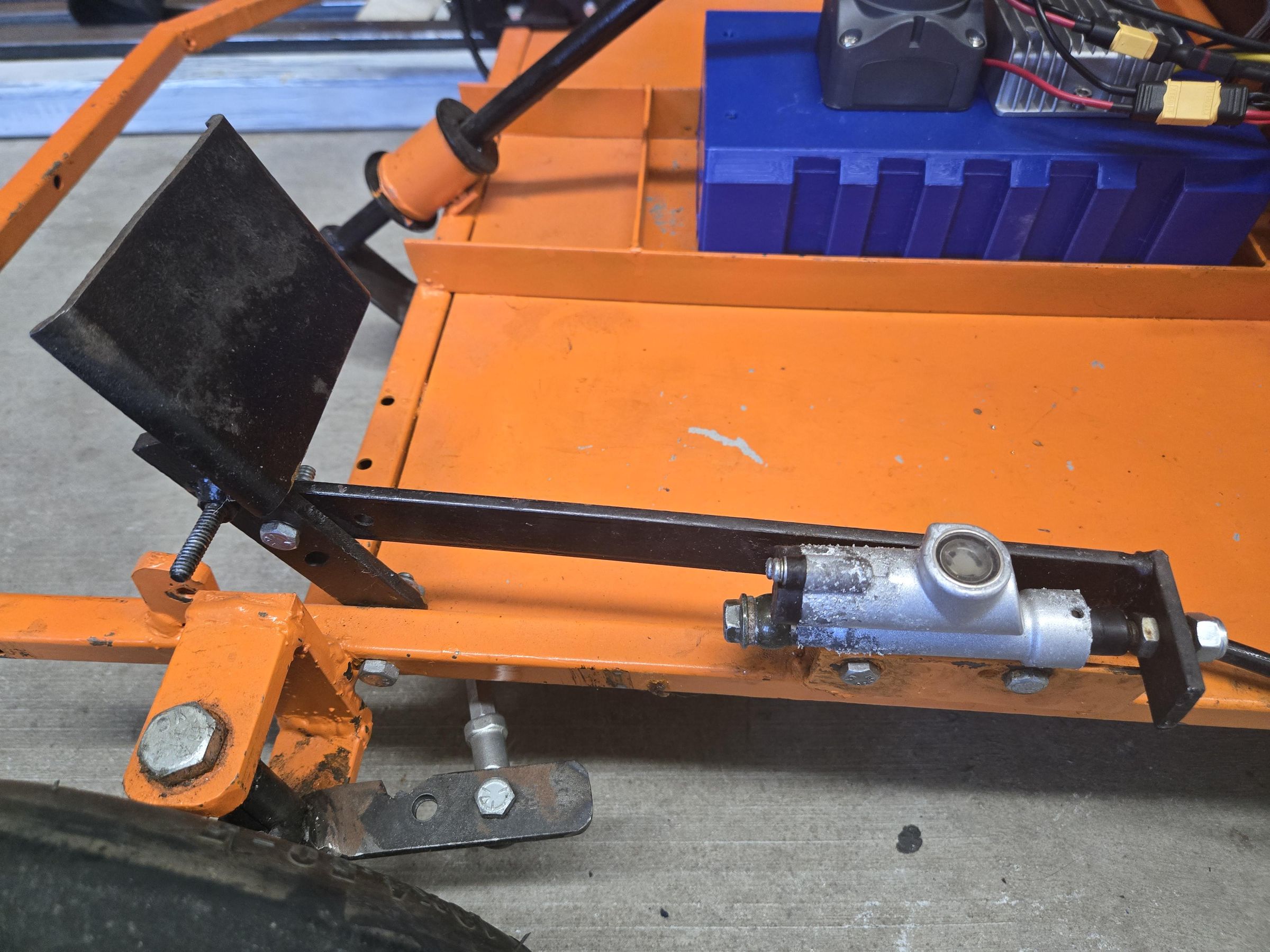
The brake pedal transfer the force from your foot to the brake piston. To fabricate the pedal, use a piece of about 1/8" steel plate and cut it to 4"x3". Then, cut a piece of flatbar to length and drill two 5/16" holes using the BRAKE PEDAL DRAWING. Weld the two pieces together and fillet the end of the flatbar.
The Brake Link is fabrciated from two pieces of flatbar using the BRAKE LINK DRAWING. Cut the two pieces and drill one 5/16" hole and one 3/8" hole. Weld the two pieces together.
Assemble the pedal and link together as shown. Don't tighten the locknuts all the way, allow for a little play in the pedal and link so it moves freely. Then tighten the M8 nut at the end of the piston to secure the link.
Floor Panel
List of Tools Required
- Aviation Snips
- Hand Drill or Drill Press
- Impact Driver
- Step Drill
- 1/4" Drive Bit
List of Materials
- 23.5" x 17.75" Steel Sheet Metal (16-26 guage)
- #8 x 1/2" Self Tapping Screw Hex Flanged
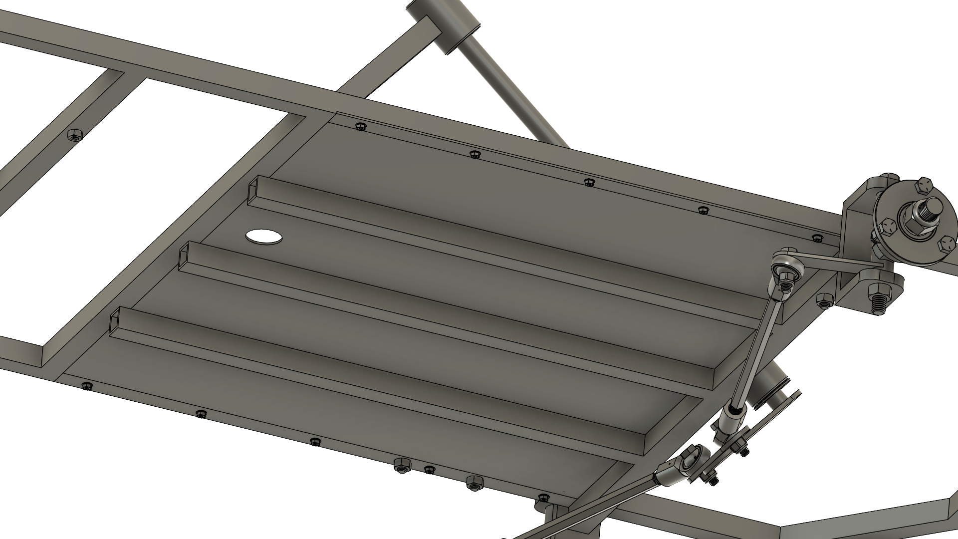
The floor panel is the structural piece to rest your feet. It is fabricated from sheet metal between 16-26 gauge, any works. Use the FLOOR PANEL DRAWING to cut the sheet metal to size using aviation snips. Then, drill a 1" hole using s step drill bit. This hole is where the cables pass through so accuracy is not important.
Grab the Floor Panel you just fabricated and slide it through the top frame under the steering column. The left and right side should be underneath the frame tubing while the middle section should sit on top of the middle tubing section. Use an impact driver to screw the Floor Panel to the Frame on the left and right side only using the self tapping screws.
Downloads
Battery Housing
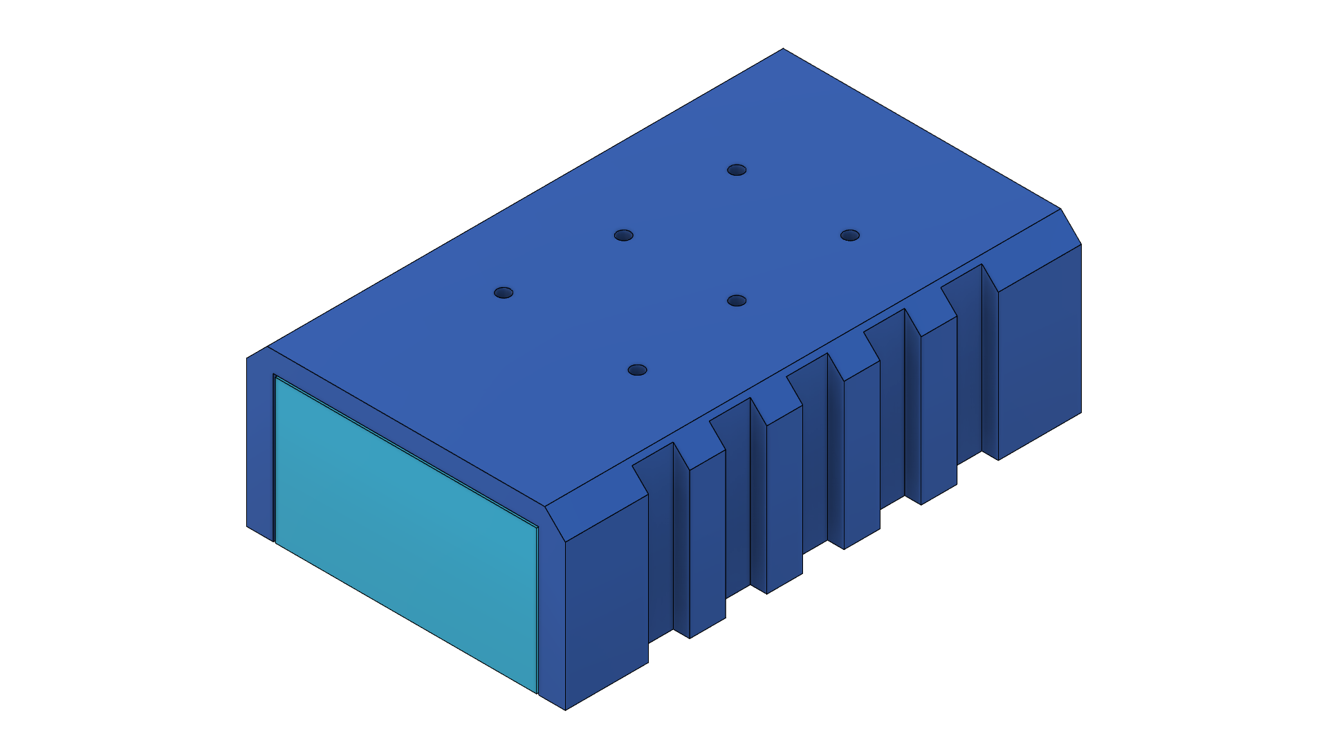
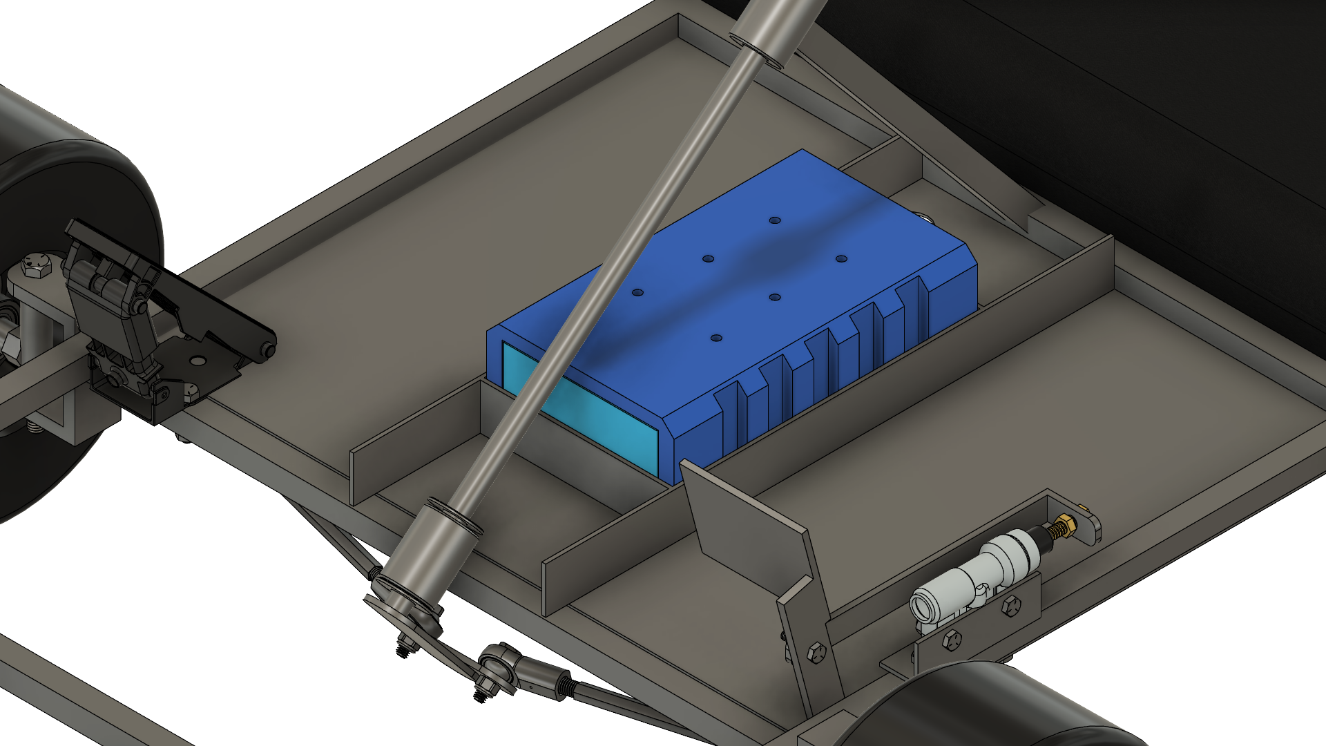
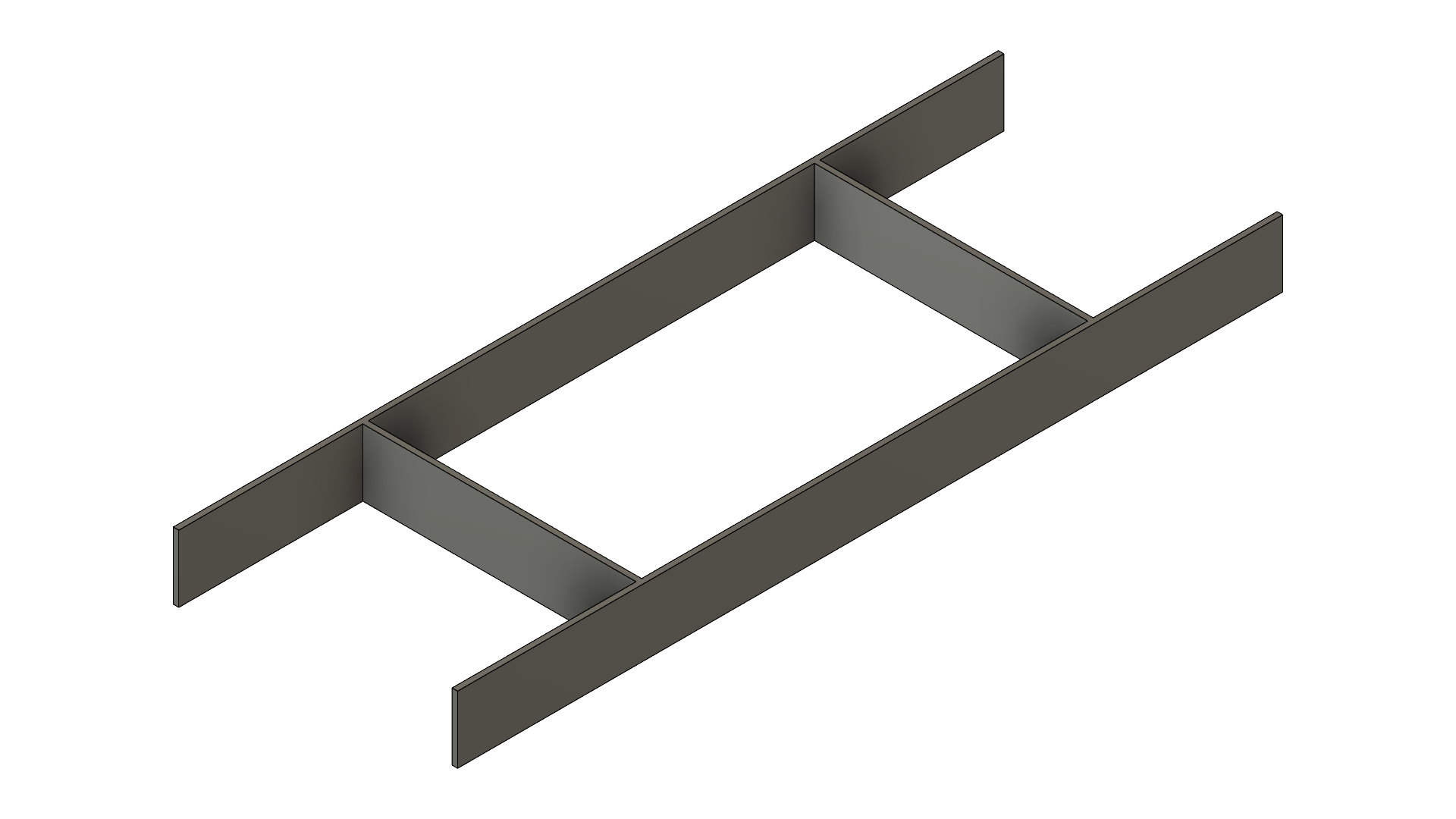
The battery housing stores the battery module in the front of the vehicle. Follow the BATTERY HOUSING DRAWING to construct it using 1.5" flatbar and welding it together. make sure to not weld the inside corners which the battery slides into or else it wont fit.
Once the Battery Housing is made, weld it to the frame so it sits underneath the Steering Column and centered on the Floor Panel. Only weld to the frame, do not weld it to the sheet metal floor.
3D print this battery cover using the stl provided.
Insert the battery into the Battery Housing and slide the 3D printed cover over it.
Seat
List of Tools Required
- Woodcutting Saw
- Drill Press or Hand Drill
- 1/4" Drill Bit
- Clamps (optional)
- Utility Knife or similar
- Heavy Duty Staple Gun
- 7/16" Socket Wrench
List of Materials
- [2] 18" x 22" Plywood, 3/4" thick
- [2] 18" x 22" Foam Cushion, 2" thick
- 2 yards of vinyl wrap
- [8] 1/4"-20 Carriage Bolt, 2" long
- [8] 1/4"-20 Nuts
- Staples for Woodworking (any size less than 1/2")
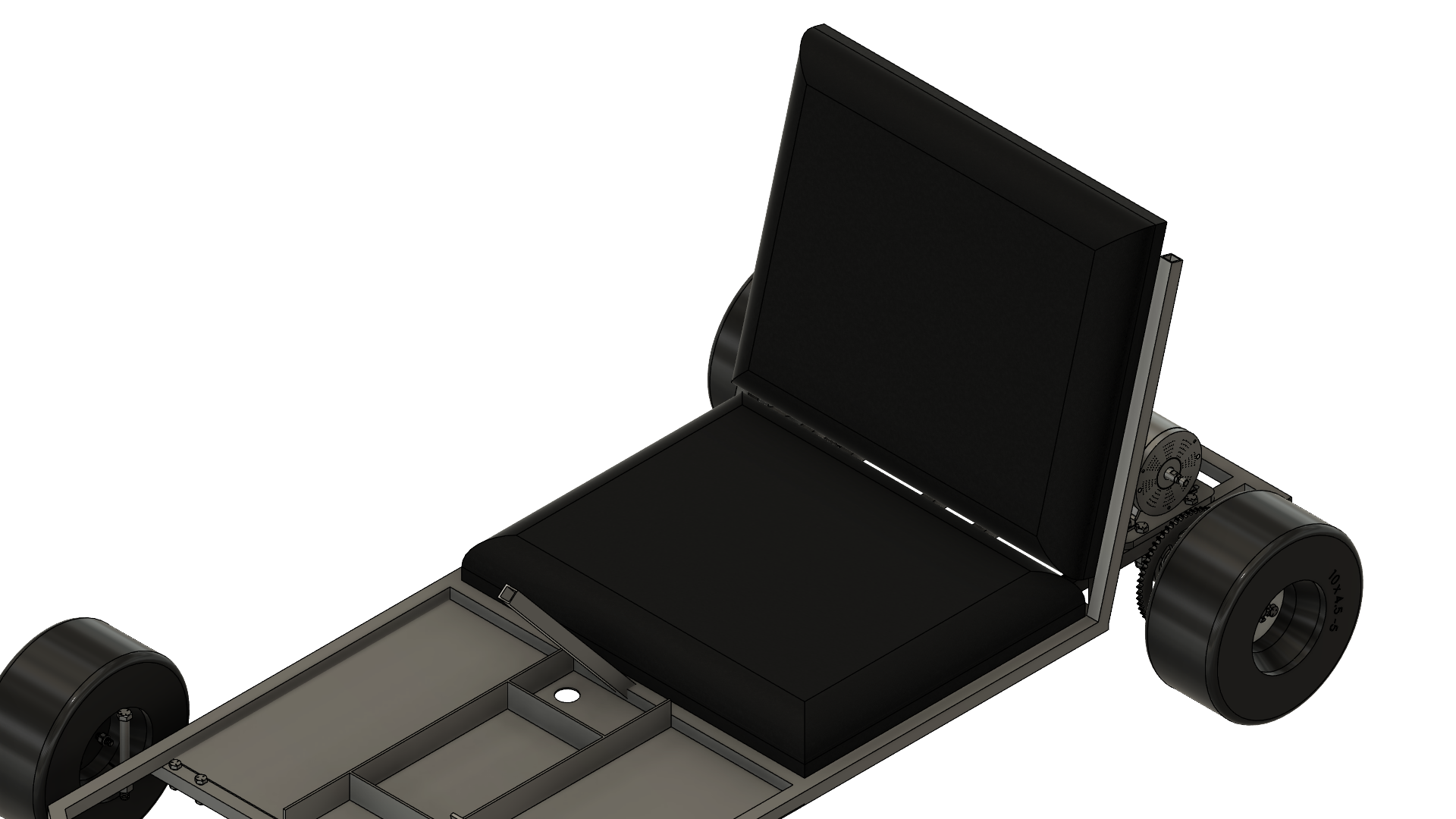
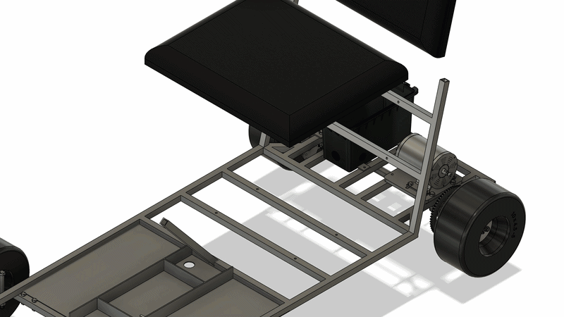
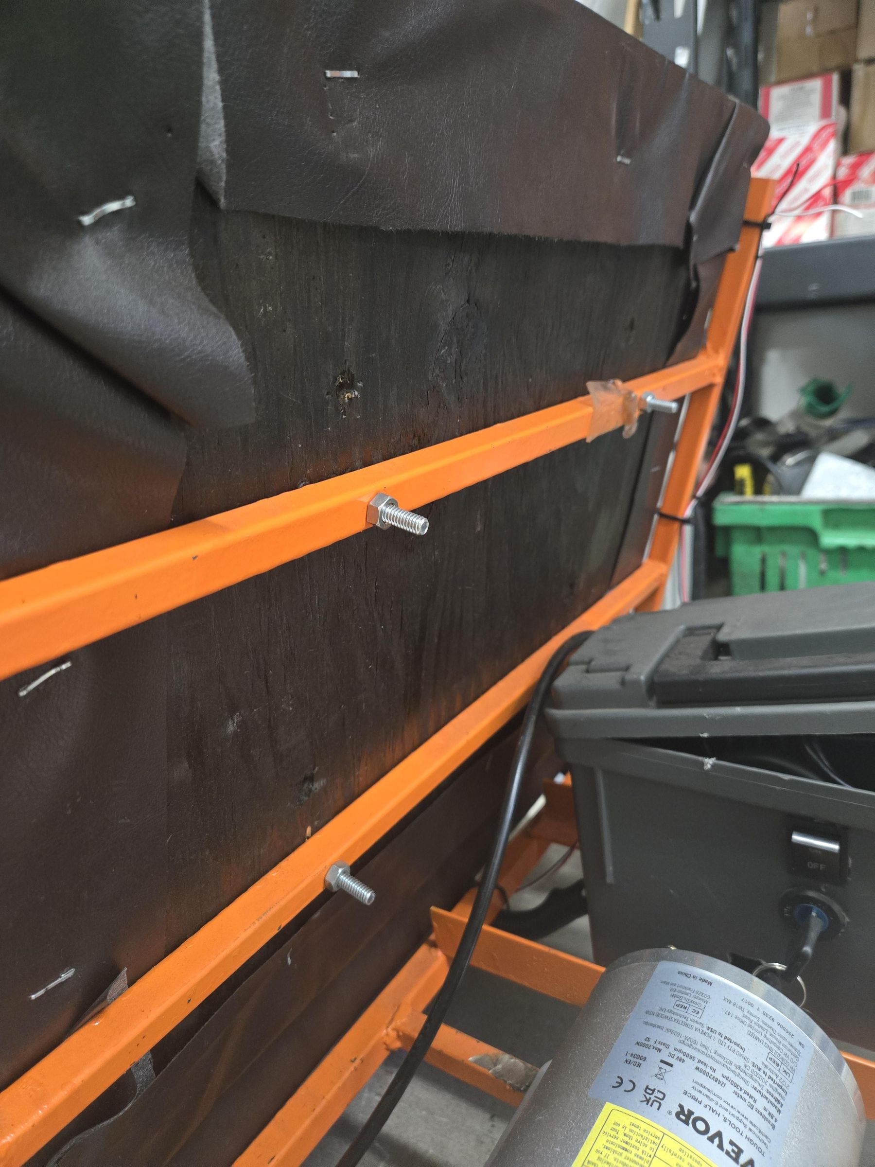
The seat comes in two parts, a top and bottom. These are custom made from 3/4" plywood, cushion foam, and vynil fabric. Both top and bottom sections are made in the same manner just with slightly different diemsnions.
First, cut out a piece of 3/4" plywood following either drawing. Then drill x4 1/4" holes using the same drawing. These holes need to match the holes on the frame. A good trick to get the hole locations right is to clamp the plywood on the frame and drill the four holes using the frame as a guide. This will make sure all holes are positioned correctly.
Next, use a utility knife or similar to cut the cushion foam to the same size as the plywood. Also cut the vynil wrap to size. A good way to do this is by placing the cushion on top of the plywood and wrapping the vynil around the top and under. The back side of the plywood must be exposed so the holes are not covered by the vynil wrap. Draw a line on the wrap and cut it.
Finally, assemble the pieces by inserting the 1/4" carriage bolts into each hole, placing the foam cushion on top of the bolt heads, and wrapping it all together with the vynil wrap. Then, use a heavy duty staple gun to staple the vynil to the back side of the plywood. Install the seat so the bolts pass through the frame and secure it with nuts.
Repeat this same step with the other part of the seat. Below is a video showing the process.
Downloads
Controller Housing
List of Tools Required
- Metal Cutting Saw
- Drill Press or Hand Drill
- 1/4" Drill Bit
- 7/16" Socket Wrench
- Stepdrill
- 4mm Allen Key
List of Materials
- 1/8" x 1" Steel Flatbar, 12" long
- [4] 1/4"-20 Hex Bolt, 1.25" long
- [4] 1/4"-20 Hex Bolt, 1" long
- [8] 1/4"-20 Nuts
- Ammo Box
- Motor Controller
- [2] M5 Socket Head Bolt, 10mm long
- [2] M5 Nut
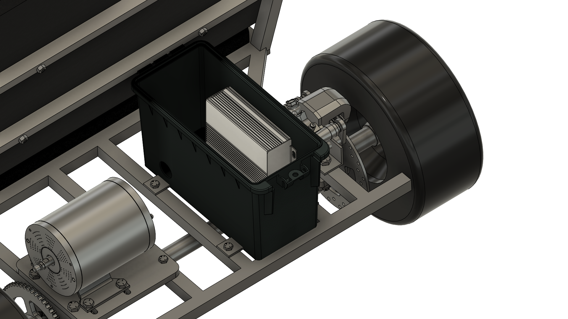
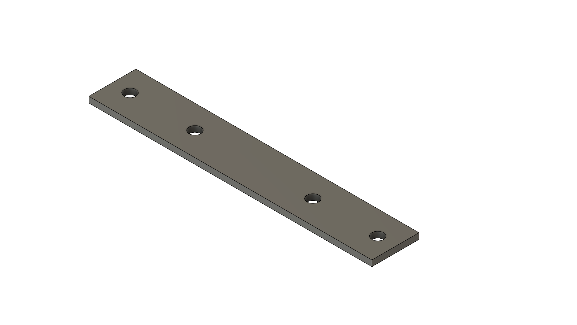
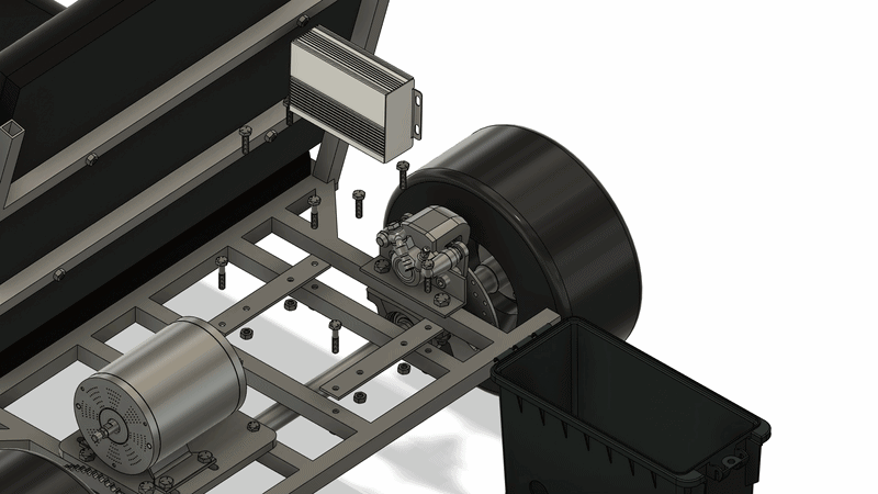
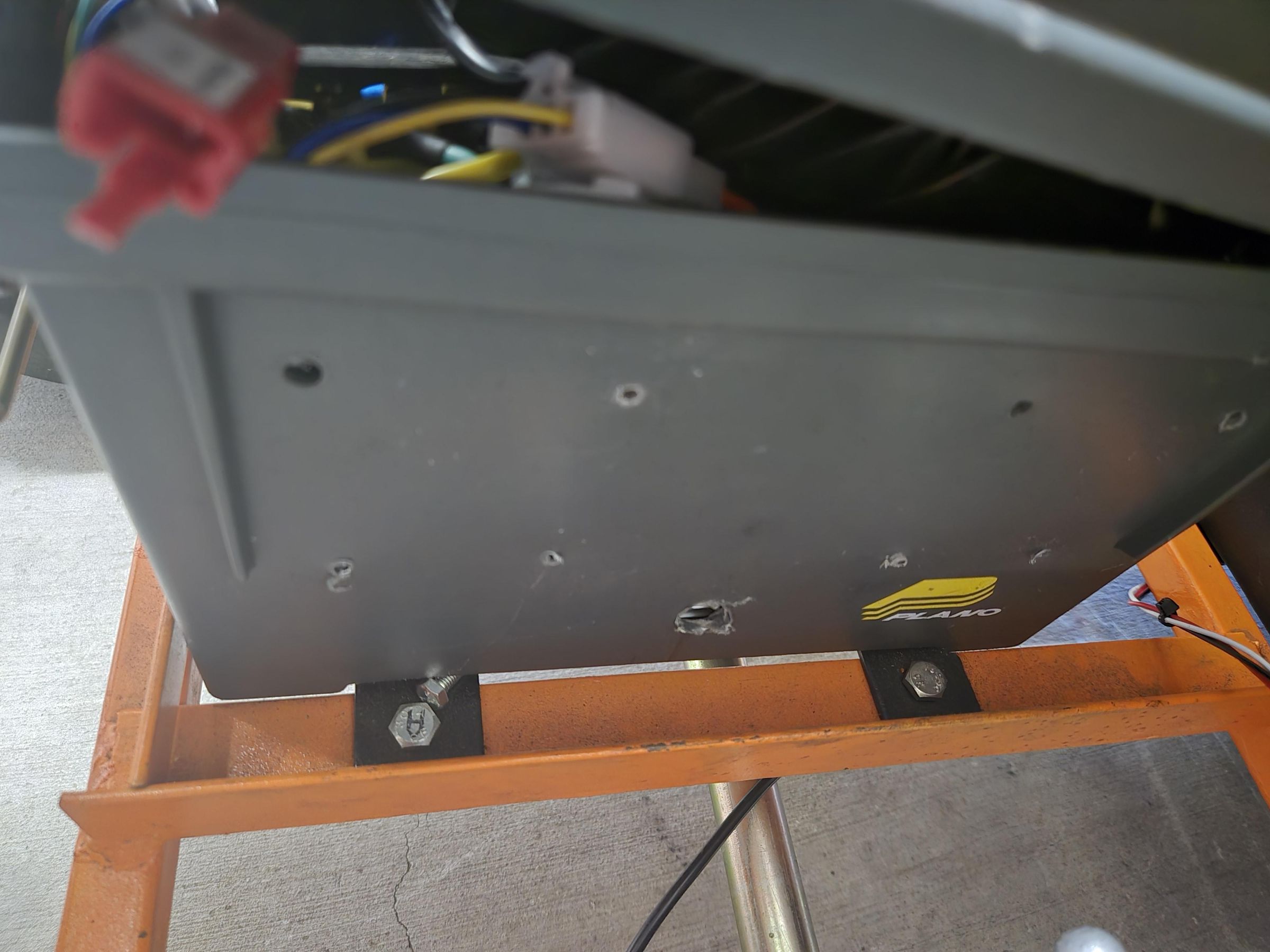
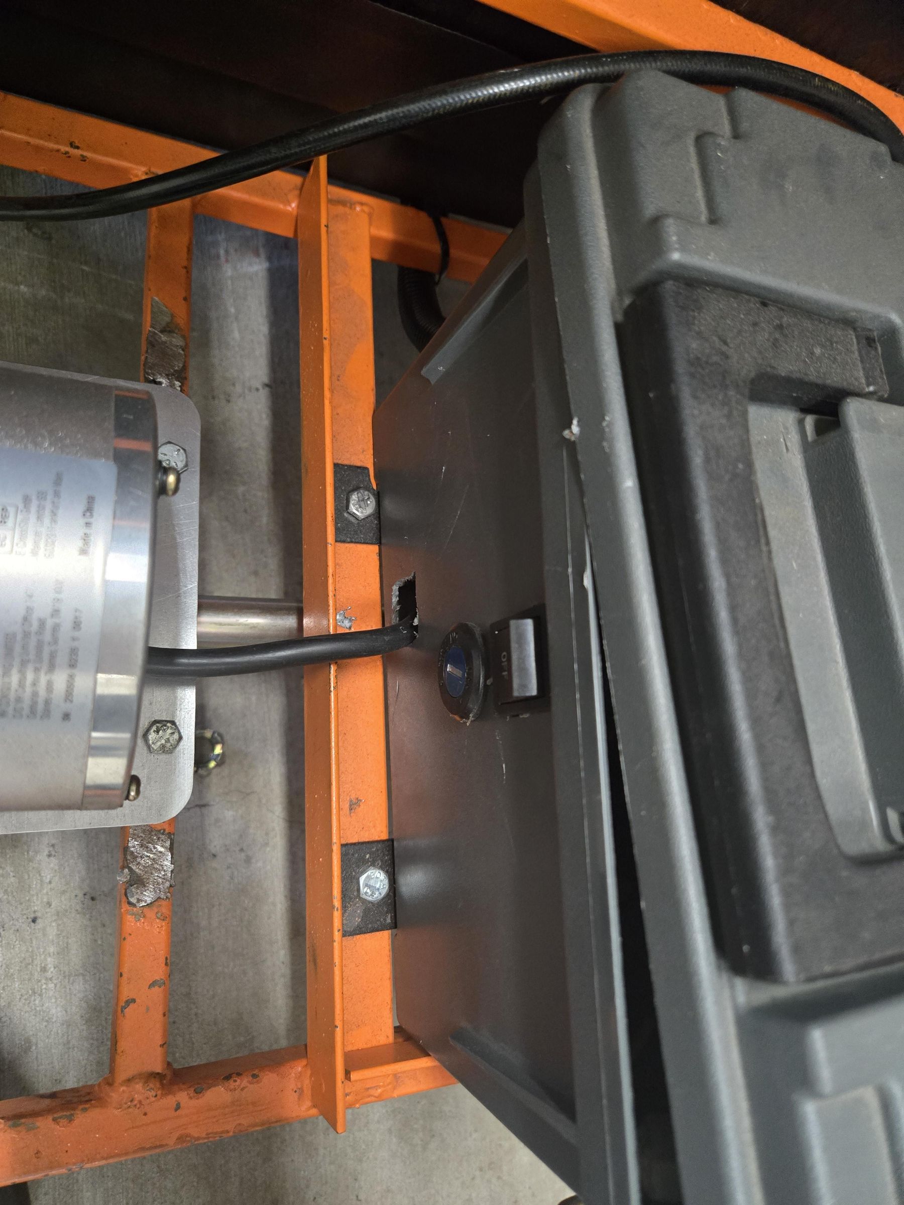
The Controller Housing stores the motor controller inside a storage box. The storage box is purchased from Harbor Freight. Begin by following the FLATBAR BOX MOUNT drawing to make 2 total pieces. Then, mount the pieces to the rear side of the frame in between the motor and brake caliper using 1/4" bolts.
Next, place the box on top of the Flatbar pieces so it is centered in between and mark the holes on the box from underneath. Drill out 4x 1/4" holes from the marked locations on the box.
Use a step drill to drill one hole on the left face and one on the rear face both about 1" in diameter, this allows cables to pass through.
Mount the Controller Housing box with four 1/4" bolts. Finally, mount the controller inside the box so the bolt brackets are flushed with the right side wall. Drill two 5mm holes that line up with the controller mounting holes and secure it in place with two M5 bolts.
Downloads
Foot Throttle
List of Tools Required
- 1/2" Socket Wrench
List of Materials
- [2] 5/16"-18 Hex Bolt, 1" long
- [2] 5/16"-18 Nuts
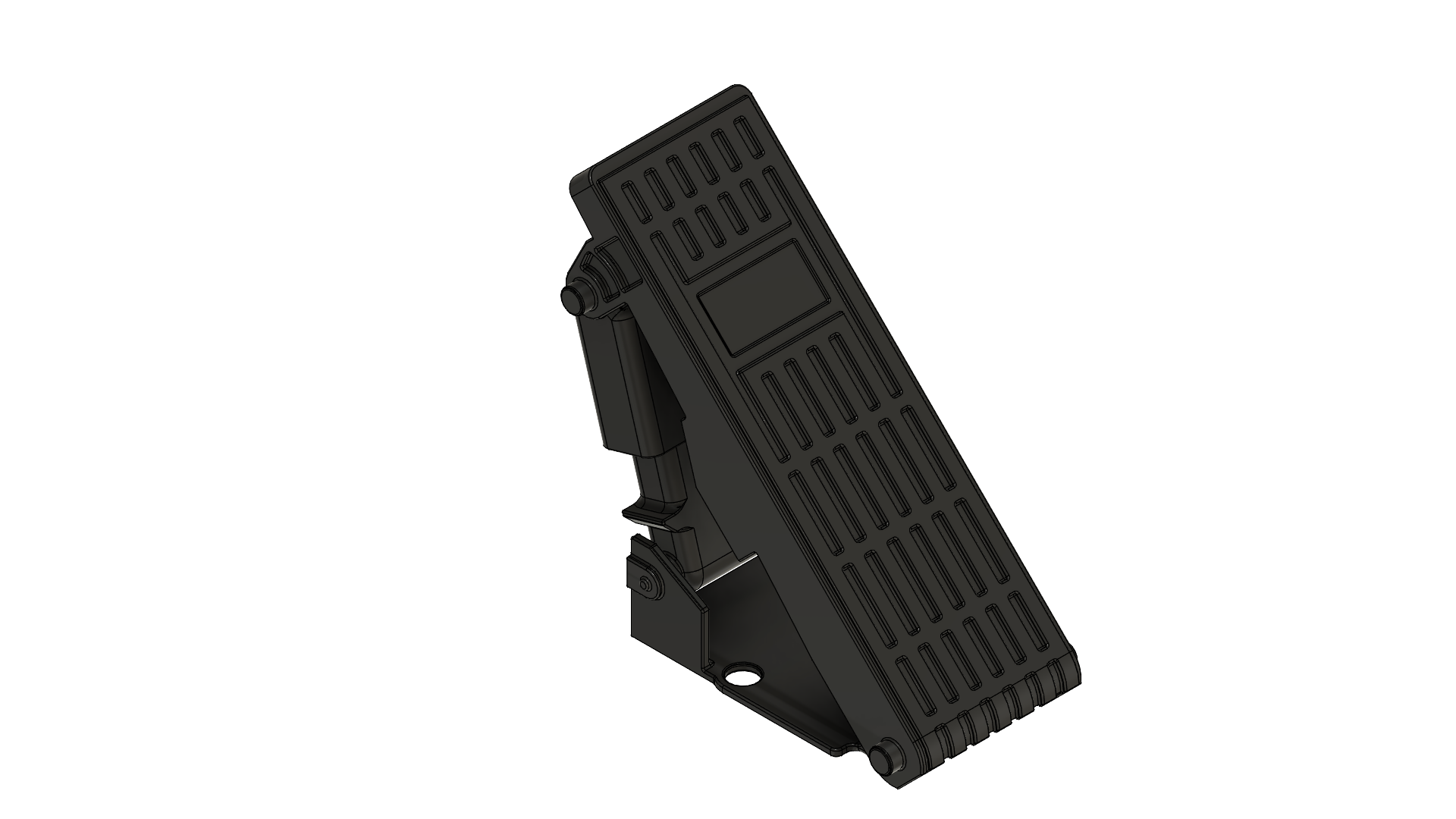
- Electric Foot Throttle
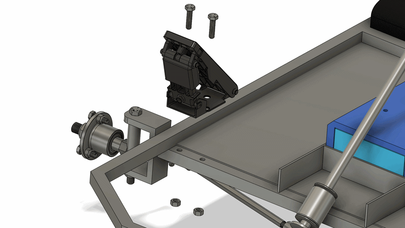
The Foot Throttle mounts to the front right using two 5/16" bolts. If any welds get in the way, grind them down. Run the wire underneath the frame.
Battery Wiring
List of Tools Required
- 11/16" Socket Wrench
- Soldering Iron
- Wire Stripper/Crimper
List of Materials
- 12 or 14 AWG Wire (Red & Black)
- Heat Shrink
- XT-60 Battery Connector (Male and Female)
- Power Switch
- [2] 3/8" Ring Terminal
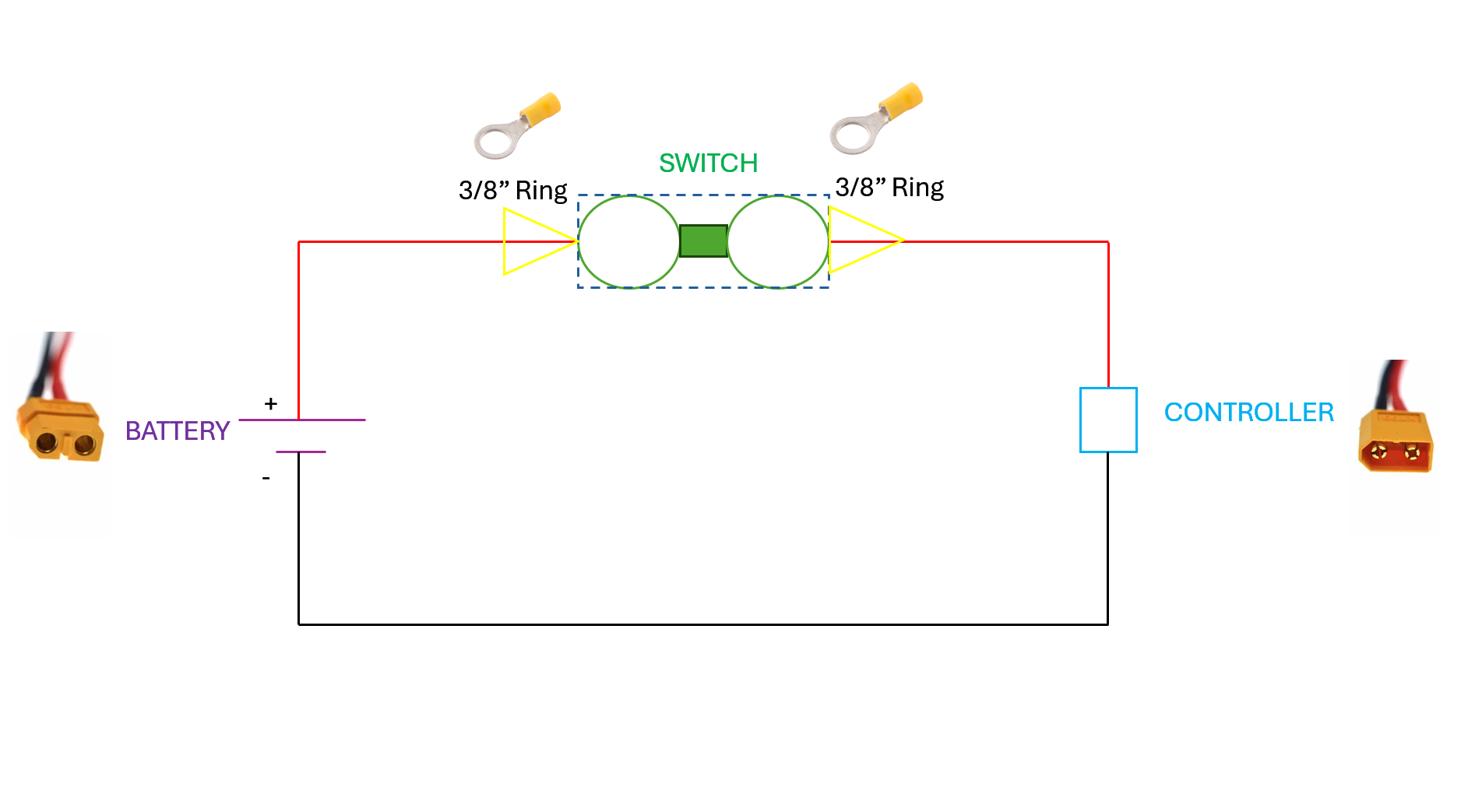
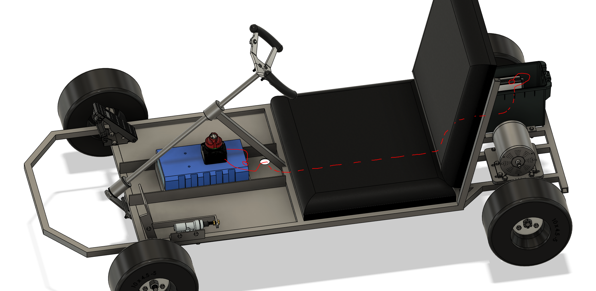
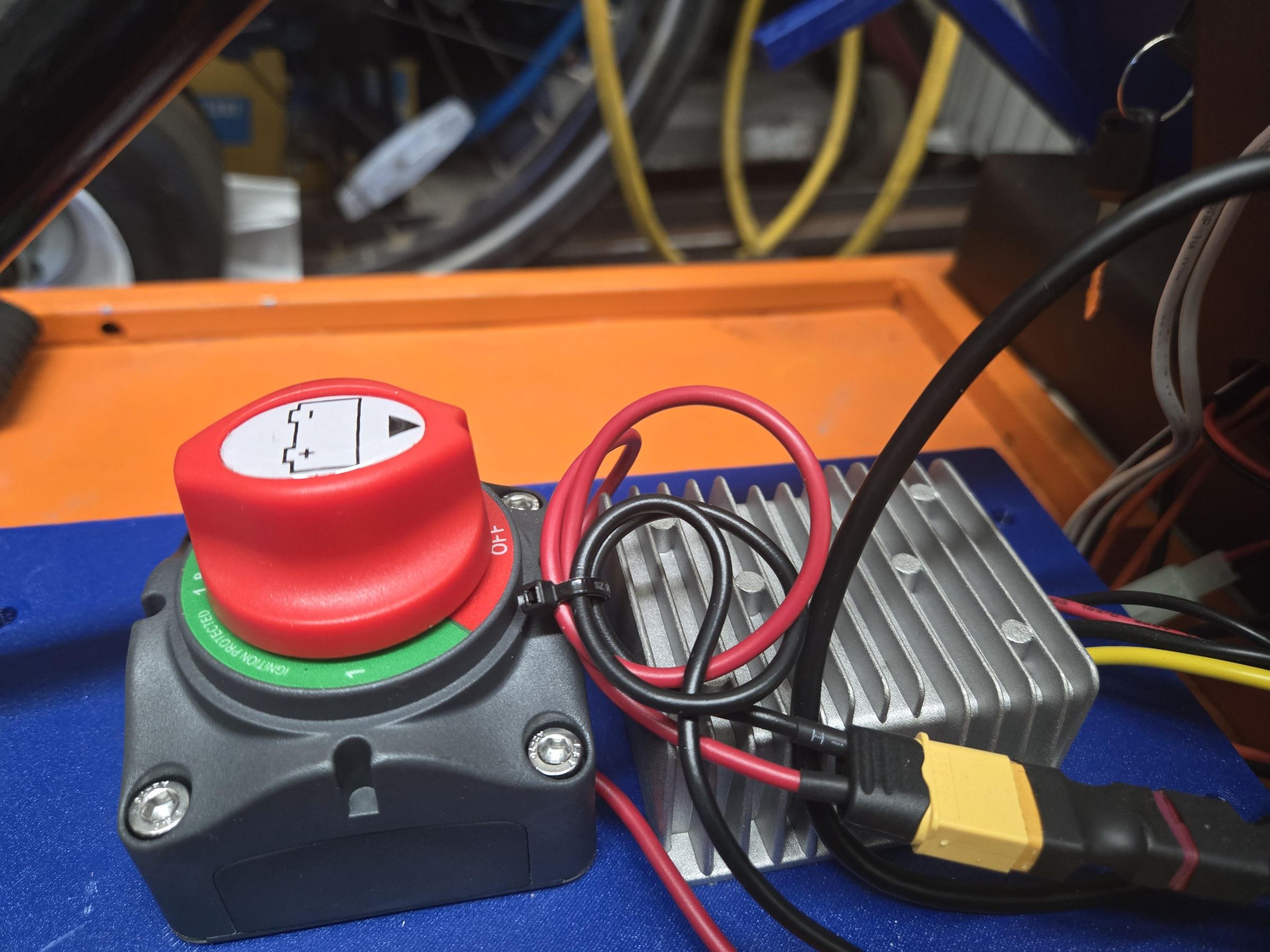
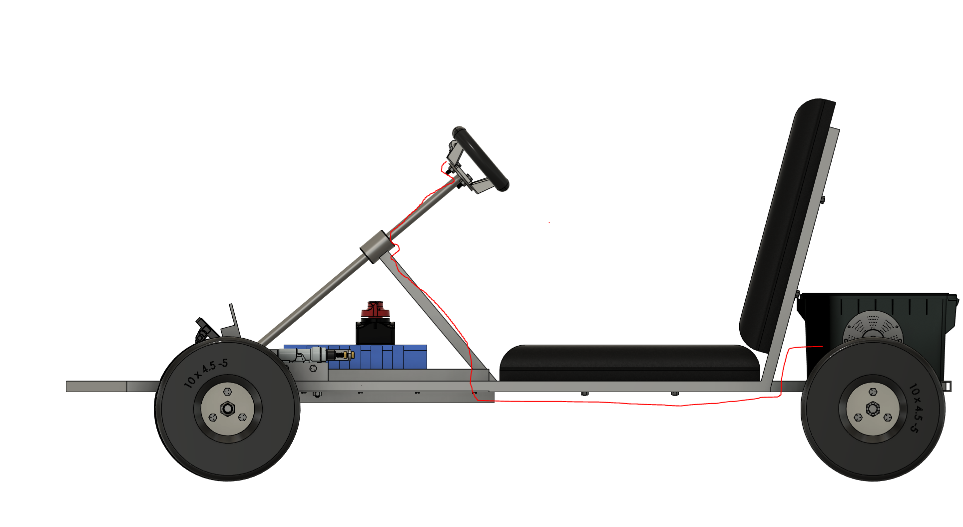
To wire the battery use 14-12 awg wire only. Follow the diagram shown, it shows a basic circuit with a switch placed in between the battery and controller to disconnect the battery. Run wire from the battery to the controller passing underneath the frame, refer to image for wire travel. This will tell you the length of wire to cut for positive and negative . The positive wire will then be cut near the battery start since the switch is mounted directly on top.
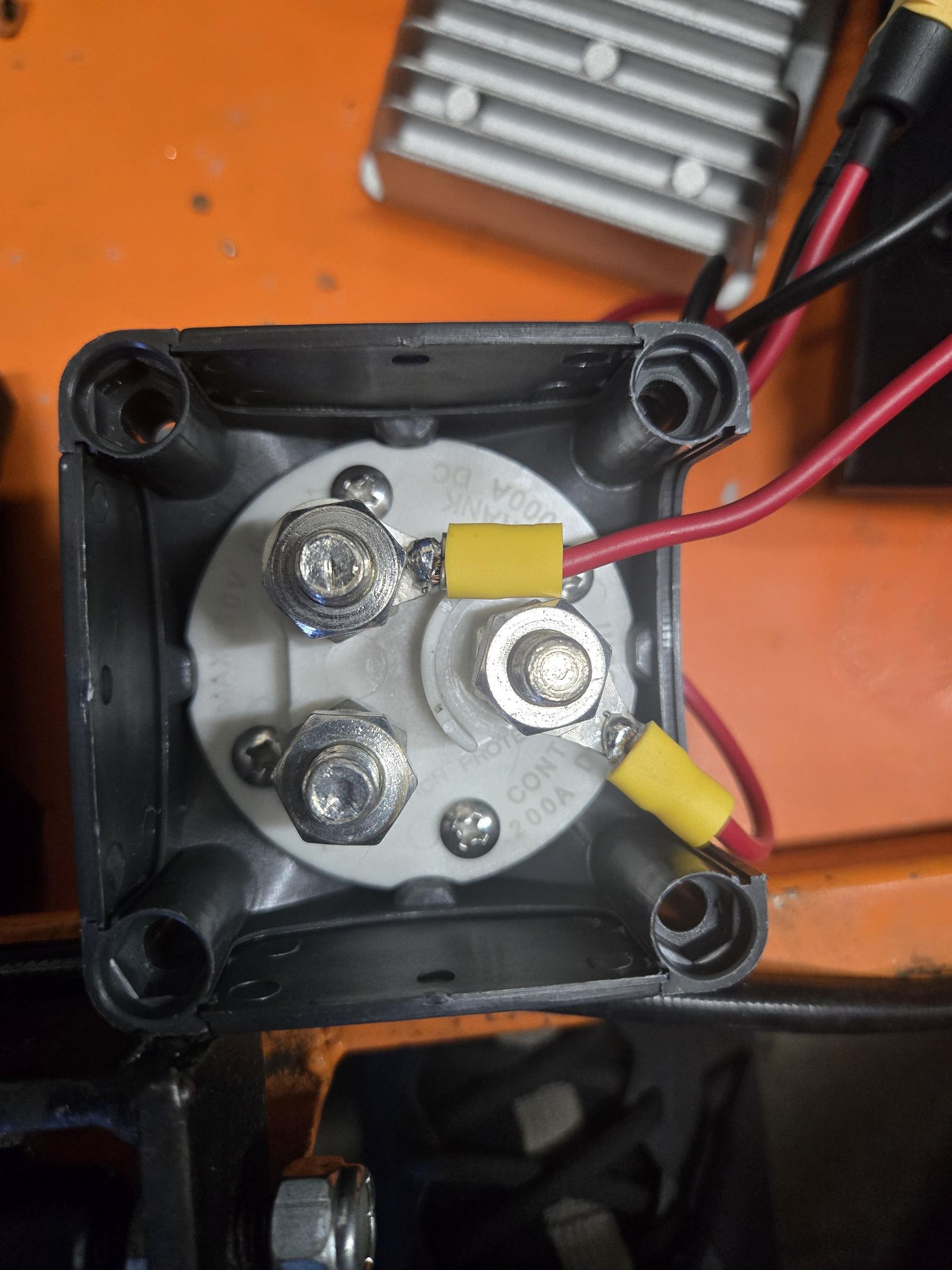
The switch is connected with two 3/8" ring terminals on the positive line of the wire. Crimp the section that was cut before so the rings can connect to each other. Install the rings on the two studs inside the power switch and tighten them with a 11/16 socket wrench.
To connect the wire to battery, use a XT-60 connector and solder the wire to each pin. Same process for connecting the wire to the controller.
Power Switch
List of Tools Required
- Soldering Iron
- 4mm Allen Key
List of Materials
- Power Switch
- [4] M5 Socket Head Bolt, 25mm long
- [4] M5 Brass Heat Insert, 6mm long
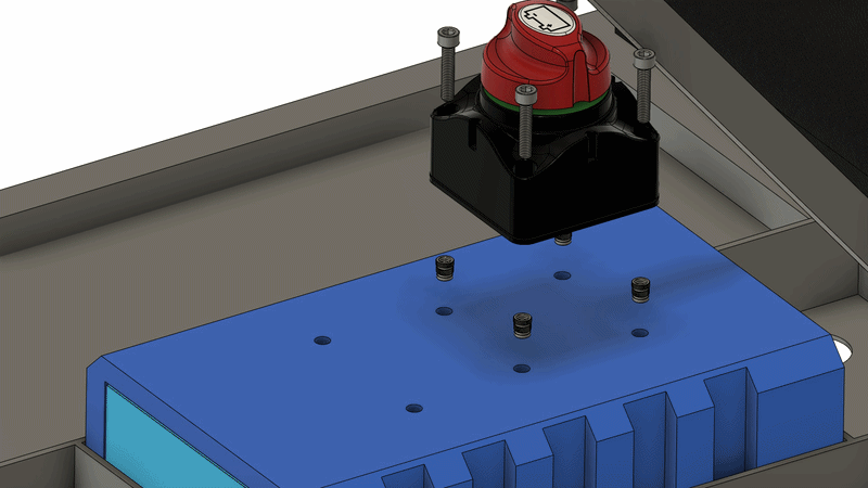
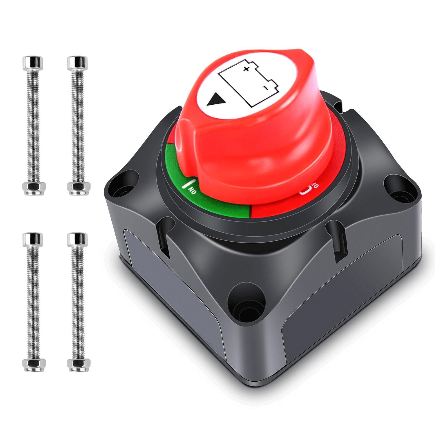
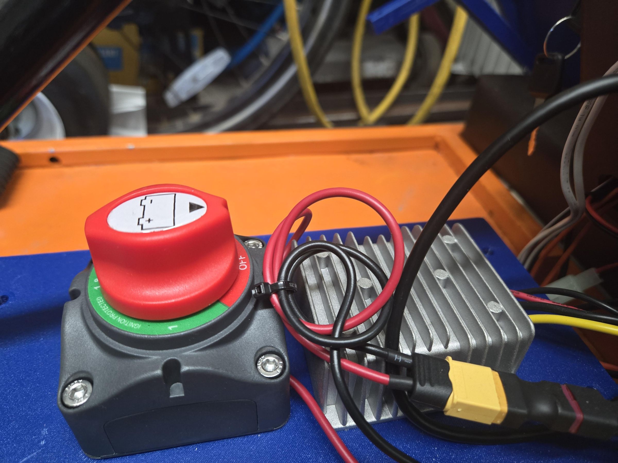
The power switch is installed on top of the battery cover. Insert 4 M5 Heat Inserts into the top four holes using a soldering iron. Then, install the power switch using 4 M5 bolts.
Reverse Switch
List of Tools Required
- Crimp Tool
- Wire Stripper
- Soldering Iron
List of Materials
- 12mm Latch Button
- 18-22 AWG Wire
- Electronic Connector Kit
- Zipties
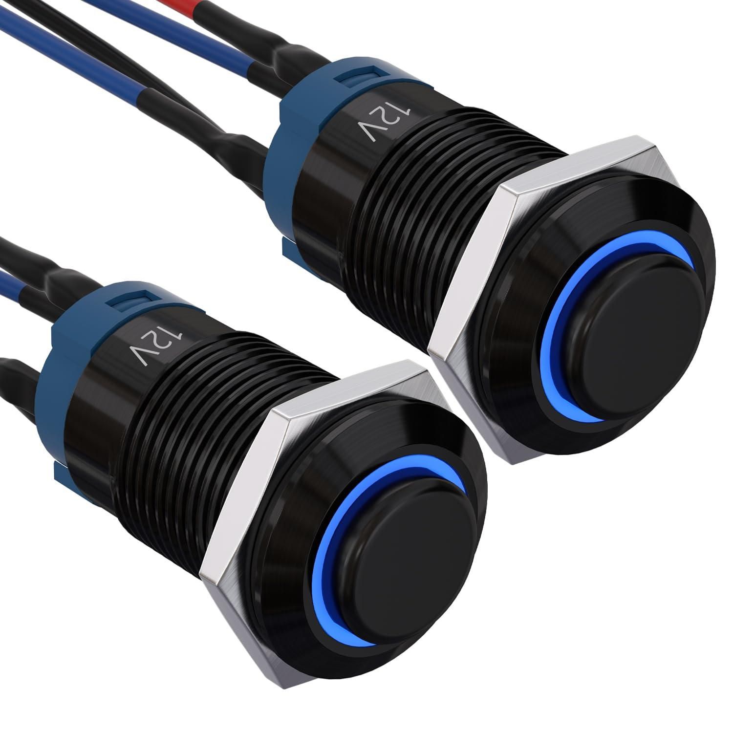
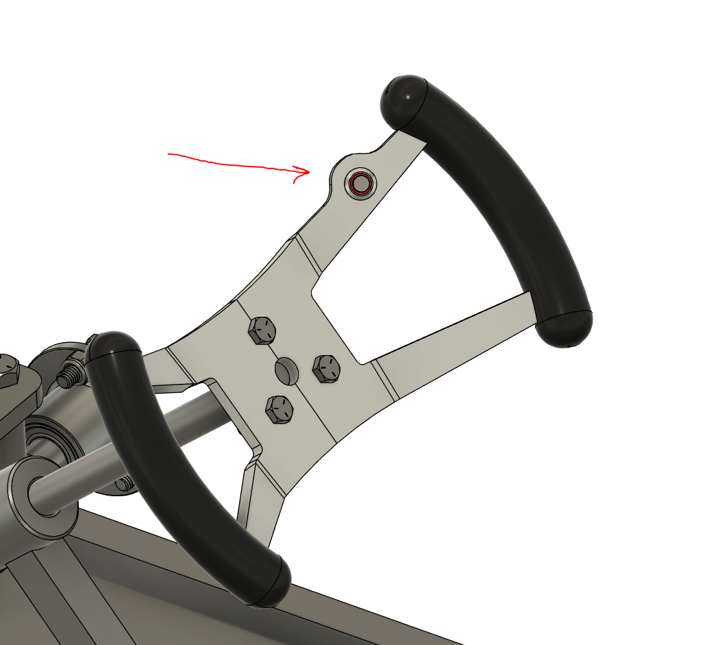
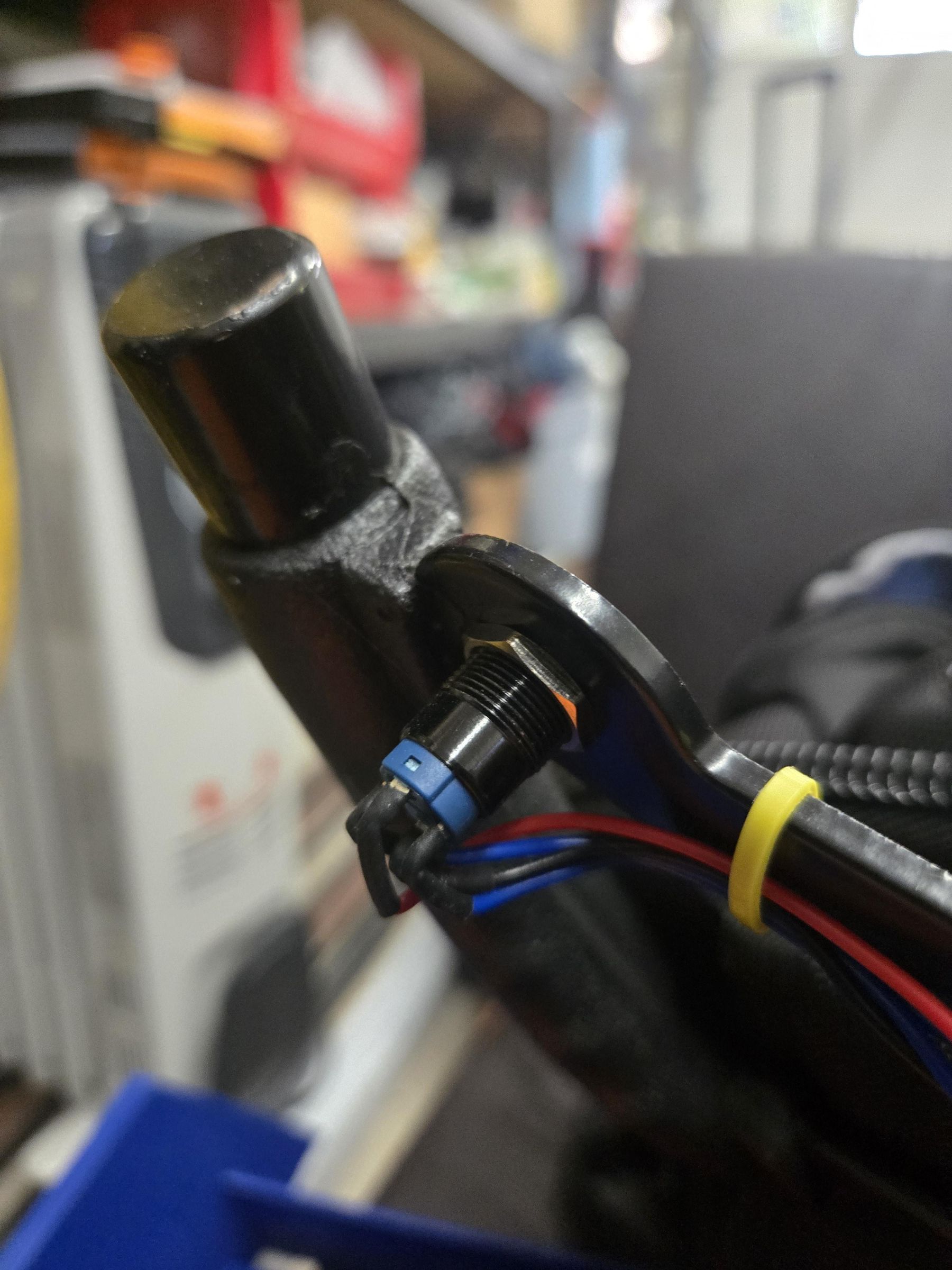
The reverse switch mounts to the steering wheel 12mm hole. Remove the nut, slide the button through, and tighten the nut with a wrench.
Splice 2 wires to run from the back steering wheel to the controller housing. Follow the image for wire routing.
Solder one end of the two wires to the button. There might be 4 wires coming from the button so use a multimeter to test continuity since only two of those will pass current through.
The other end of the wire will connect to the reverse switch of the controller. Check the manual that was included with the motor controller to verify connection. Use the Connector Kit to crimp the two wires to a 2-prong connector and connect it to the reverse switch.
The reverse switch basically is a jumper so the polarity doesn't matter.
Foot Throttle Connection
List of Materials
- Foot Throttle
- Zipties
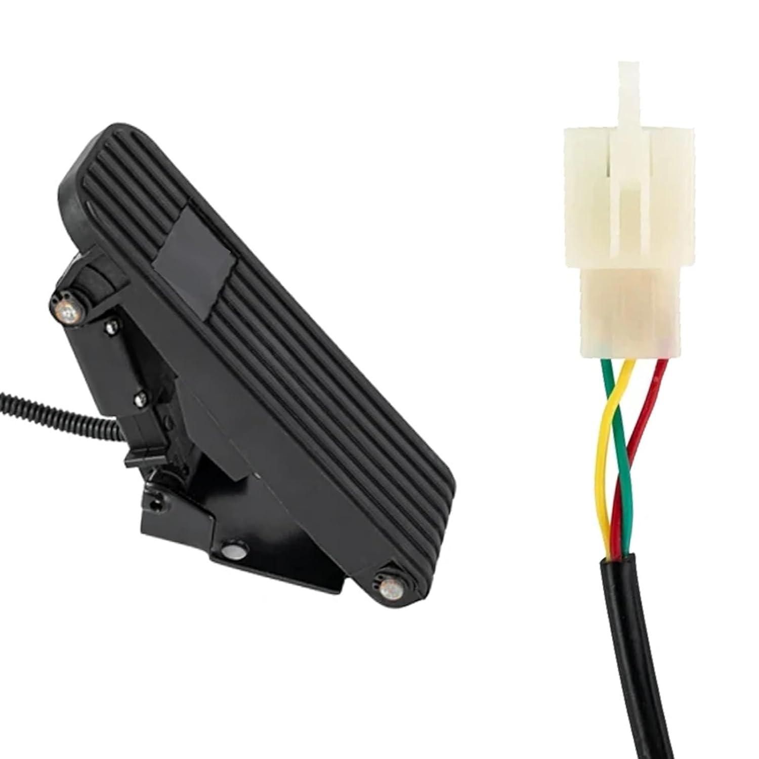
The foot throttle wires run through the bottom of the frame and go inside the controller housing. Connect the throttle to the throttle connector from the controller. Check the manual included with the motor controller for verification.
Brushless Motor
List of Tools Required
- Phllips Screw Driver
List of Materials
- Brushless Motor
- Controller
- Terminal
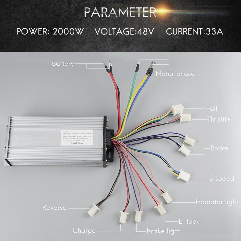
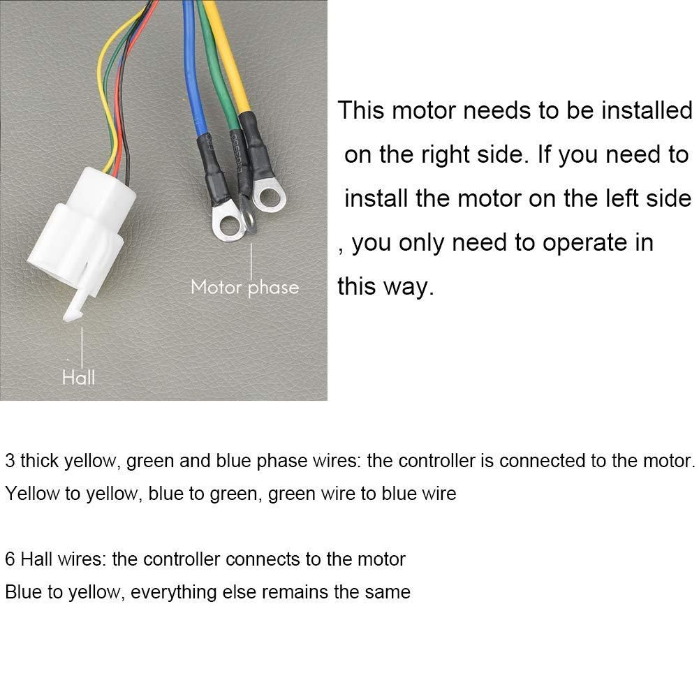
Connect the brushless motor to the controller. There are 3 thick wires which connect to a yellow terminal container that was inline with the kit. Connect the controller wires matching to the same terminal.
Next, a 6-prong connector connects to the controller directly. Double check the manual included with the motor controller for connections.
Fin
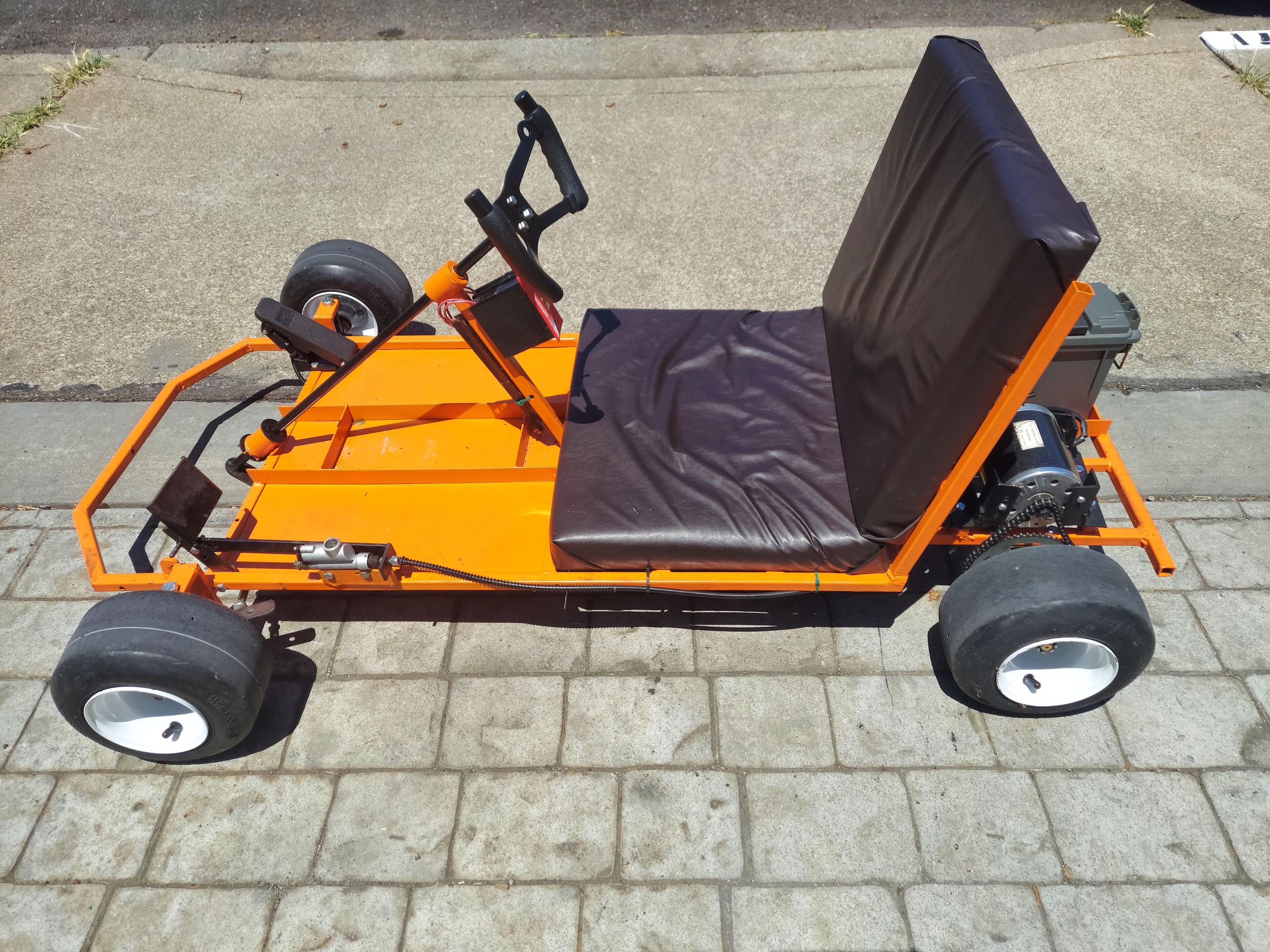
Congradulations! The build is complete and your hard work has paid off.
The Kart is turned on by flipping the switch located on top of the battery. To reverse the motor, simply press the Reverse Button located on the right hand side of the steering wheel.
To charge the Kart, make sure the power switch is in the OFF position and plug in the charging cable to the battery.
The kart is designed for a maximum speed of 25 MPH with a maximum weight capacity of 200lb not including the kart itself.
If you have any questions or feedback regarding this Instructable, feel free to reach out to me via messages or through Discord: redxdeath