555 Timer IC Toy Ambulance Van
by weirdcircuits in Circuits > LEDs
18 Views, 0 Favorites, 0 Comments
555 Timer IC Toy Ambulance Van
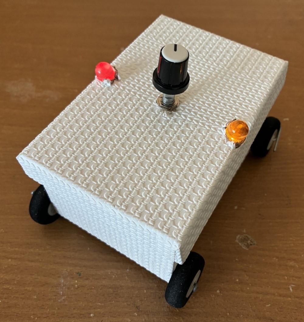

This article shows you how to make a toy ambulance van with 555 timer IC (integrated circuit). The 555 timer IC turns the buzzer ON and OFF.
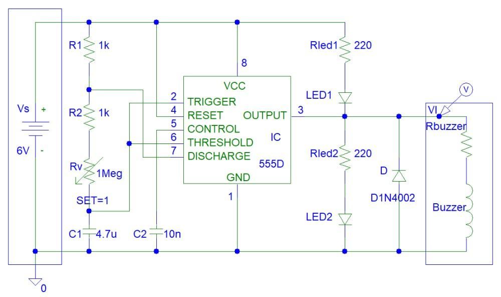
The buzzer is modeled as a coil. This is why I used a diode to prevent discharging currents from buzzer from damaging the output of 555 timer.
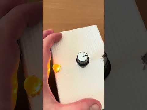
The first video (26 seconds) shows the toy ambulance van working. The second video (55 seconds) shows the ambulance van working followed by the slide show of all the photos in this article.
Supplies
Components: 555 Timer ICs - 2 (you might need spare), 6 V Buzzer - 1 (you will need a 6 V buzzer that works at 4 V or 5 V because the battery voltage could be slightly less than 6 V), 8 pin Wire Wrap Socket - 1, Wire Wrap Wires (red, black, any other colour), 6 V Switched Battery Holder - 1 (a battery holder with wires that can hold four AA batteries), Bright LEDs - 4 (you might need spare), 1 Megohm Variable Resistor - 1, 1 kohm Resistors - 2, 220 ohm Resistors - 2, 4.7 uF Electrolytic Capacitor - 1, 10 nF Capacitor - 1, 1N4004 Diode - 1, 0.9 mm Thickness Metal Wire (to secure wires to matrix board), 1.5 mm Thickness Metal Wire (to make rods for wheels), Matrix Board, Gift Box, Toy Wheels - 4, Lead-Free Solder.
Tools: Wire Wrap Tool, Scissors, Pliers, Wire Stripper, 60 Watt Soldering Iron.
Optional components: Sticky Tape.
Design the Circuit
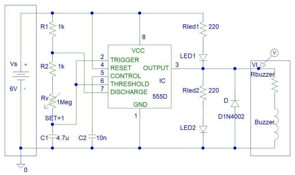
The 555 timer generates a square wave output with high time (maximum voltage) and low time (minimum voltage). The duration of high time and low time are the following (in seconds):
High Time: T1 = 0.693*(R1 + R2 + Rv)*C1, Low Time: is T2 = 0.693*(R2 + Rv)*C1
The output frequency is equal to: f = 1 / (T1+T2) = 1.44 / ((R1 + 2*(R2 + Rv))*C1)
Rv is variable resistor/potentiometer. The frequency is maximum when Rv value is zero and the frequency is minimum when Rv value is 1 Megohms.
The 555 timer oscillation frequency can be calculated online on a number of websites. One of those websites is:
https://www.digikey.com.au/en/resources/conversion-calculators/conversion-calculator-555-timer
The derivations for those equations are explained on this website:
https://analogue-electronics.webnode.page/articles
The maximum LED current is equal to:
IledMax = (Vs - Vled)/Rled
= (6 V - 2 V) / 220 ohms
= 4 V / 220 ohms
= 18.1818 mA
Those are 10 mm LEDs that need 20 mA current. Smaller LEDs need 10 mA or 5 mA current.
Simulations
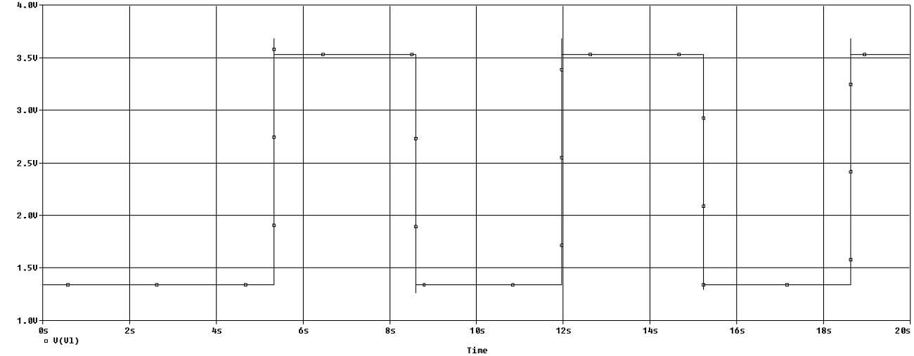
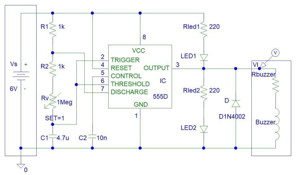
Simulations show that the maximum 555 timer oscillation period is about 6.5 seconds.
Make the Circuit
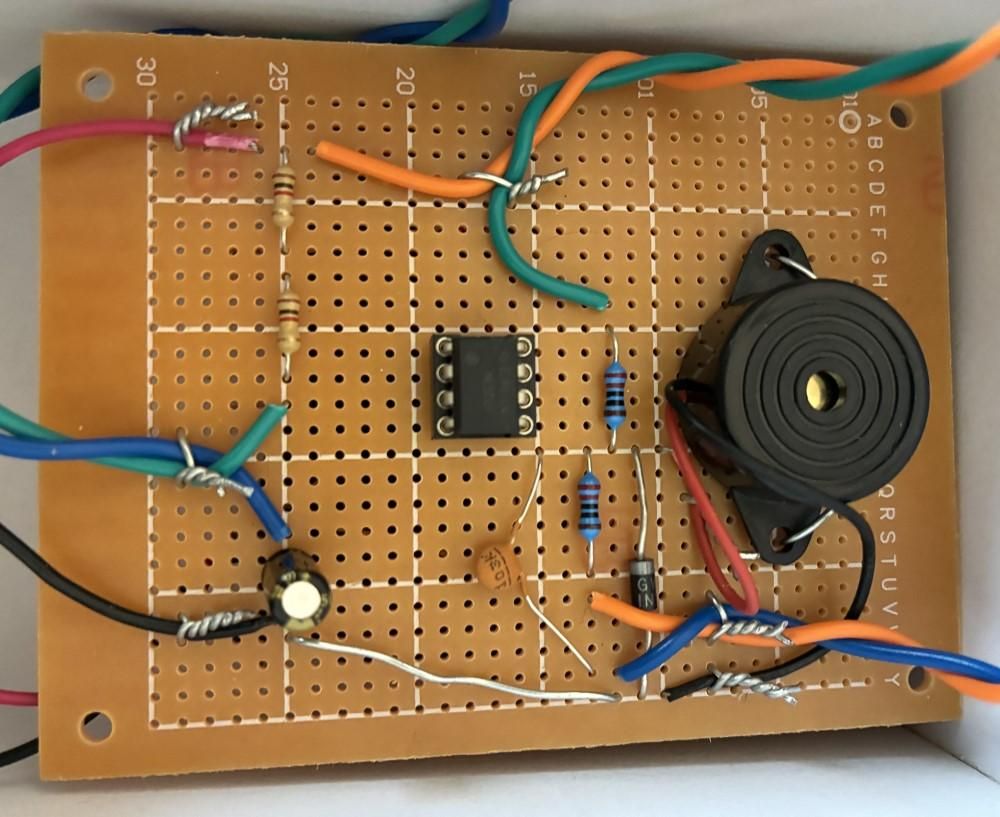
I made the circuit with wire wrap tool. I did not use as soldering iron except for soldering the LEDs to wires. I twisted the component pins together.
Encasement
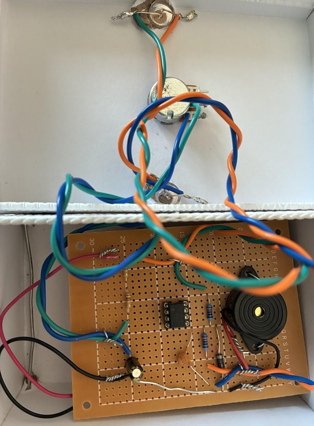
You can see from the photo that I soldered the LEDs to wires. I placed the circuit inside a gift box and made holes with scissors.
Testing

Testing showed that my circuit is working. You can see me opening the box in this video. The video is 45 seconds.