$8 GPS Receiver Hack!


GPS receivers are expensive! This neat and relatively easy hack will turn a high-quality (and cheap) GPS card into one that is usable via serial port. Then you just plug it into an Arduino or any compatible microprocessor and you are good to go!
Check out Andrzej of EmerytHacks who discovered this hack!
Watch My Video!

My video will overview the process of hacking this chip. More details and images will be provided next.
You can also check out my blog @ denialmedia.ca for more information and updates.
Materials


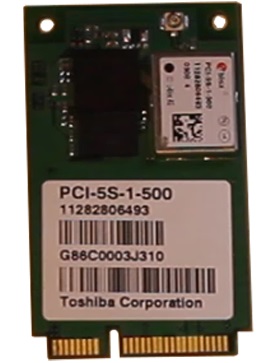
You will need to head out and buy the U-blox PCI-5S chip online. Do not choose a price any higher than $8 because that is what these chips are sold for usually. Here is an eBay link to get you started:
http://www.ebay.com/sch/i.html?_sacat=0&_from=R40&_nkw=u-blox+gps&_sop=15
You will also need a:
- Arduino
- Wires
- Male header pins (or a paperclip)
- Solder
- Soldering Iron
An antenna is needed as well. It must have a UFL connector and be an ACTIVE antenna. Here is a search query:
Soldering and Connecting


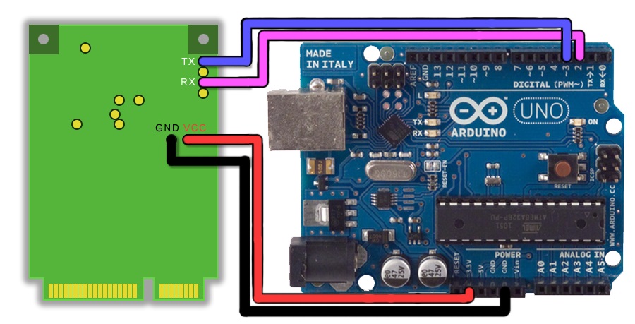
You will need to solder some wire to the connections on the back of the card. As you can see in the first image, 4 wires are needed, all of which will go to the Arduino. I recommend connecting male header pins or a paperclip so that the wire can stay in the port. If you have solid core wire this may be unnecessary.
The TX will go to pin 2, the RX to pin 3, the VCC to 3.3v, and GND to GND.
I've also built a "case" for the Arduino and GPS as part of a larger project, the Arduino autopilot. The things holding the GPS card are simply dowels that are screwed in from the bottom. They both have flat notches that I cut out using a saw.
Installing the TinyGPS++ Library
Head on over to Mikal Hart's website and download the latest version of TinyGPS++. Extract the folder using WinRAR or a similar program and drag it to your Arduino libraries' folder. By default it is (C:\Users\%User%\Documents\Arduino\libraries). Be sure to rename the folder to something without a dash.
Coding and Testing


Connect the Arduino to the computer and open up the IDE (coding program). Go to the DeviceExample:
File > Examples > tinygps > DeviceExample
Here we will make some changes. In line 8 and 9:
static const int RXPin = 4, TXPin = 3;
static const uint32_t GPSBaud = 4800;
will become:
static const int RXPin = 2, TXPin = 3;
static const uint32_t GPSBaud = 9600;
The 2 represents where the RX pin is (I connected it to digital pin 2) and the TX does the same (I left it unchanged). The U-blox chip is set to a default baud rate of 9600, so I changed the value for that as well.
In the setup section:
Serial.begin(115200);
will become:
Serial.begin(4800);
I changed it so there would be less glitches and there would be less CPU usage. (This step is optional on the MEGA)
Connecting to U-Center


U-center is a great tool for analyzing and configuring the U-Blox chips, plus it is very simple to connect to the software itself.
Go ahead and download the software from http://www.u-blox.com/en/evaluation-software/u-center.html
Upload the following code to the Arduino through the IDE:
#include <SoftwareSerial.h>
SoftwareSerial ss(2,3);
void setup()
{
Serial.begin(4800);
ss.begin(9600);
}
void loop()
{
if (ss.available())
Serial.print((char)ss.read());
if (Serial.available())
ss.print((char)Serial.read());
}
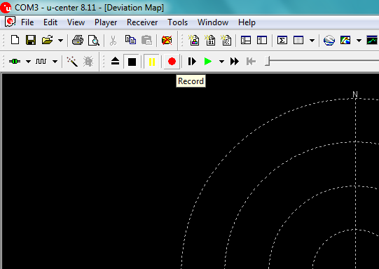
You should see a collection of strings in the serial monitor. Open up the U-center and in the top left corner change the baud rate to 4800, then connect to the Arduino using the connect button. Be sure to close any serial monitors/connections, otherwise this will not work. Click the record button, it will ask what to name a log file. Name the file and click OK.
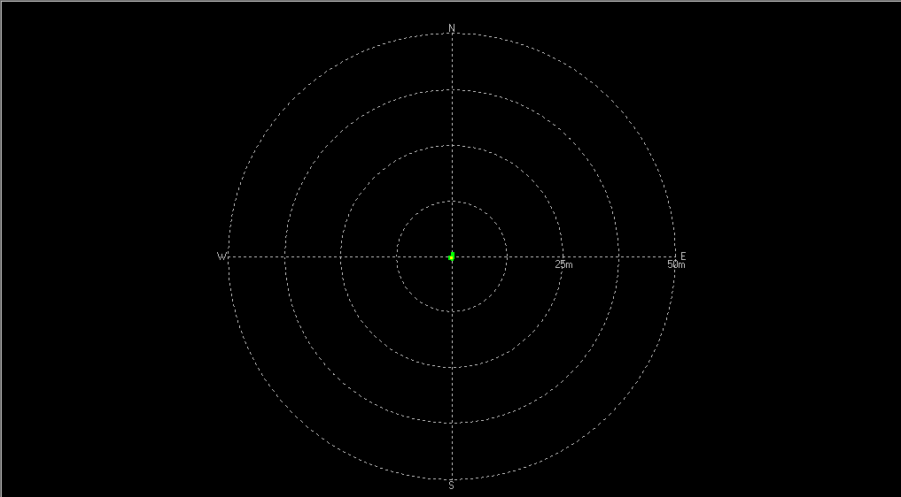
And there you go! In the view menu you can open up things like the deviation map to see how far it moves, or go full out and open up Google Earth to see where the GPS is showing itself to be. If you have any questions, I'll be sure to answer them!