A Cheap 2S2P Li-ion DC UPS for My Home Router (~$20 Usd)
by MBNZ in Circuits > Electronics
38 Views, 0 Favorites, 0 Comments
A Cheap 2S2P Li-ion DC UPS for My Home Router (~$20 Usd)
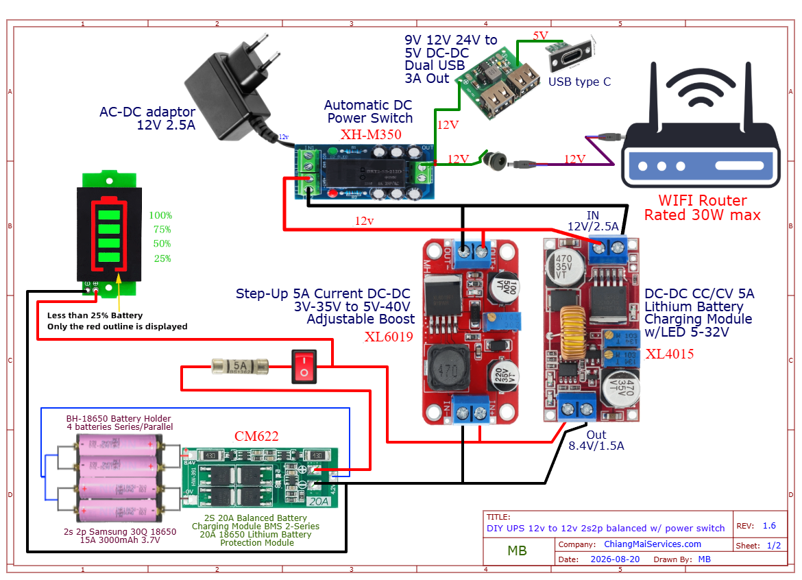
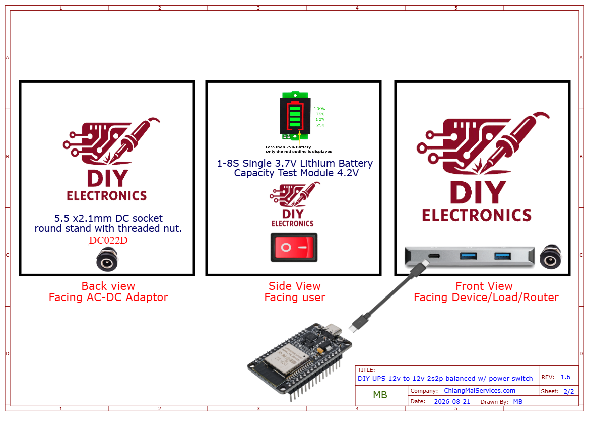
I built a DIY battery UPS for my router because apparently my home lab needs its keep the connection (~$20 usd)
I'm not an electrical engineer. I'm a DIY/homelab person with fairly limited electrical knowledge who got tired of losing the network whenever the power decided to have a bad day. I spent a lot of time reading, checking, measuring and second-guessing this project because lithium batteries are not the place to YOLO things. So this is what I built, why I built it, what I learned, and where I might still be wrong. If you actually know what you're doing with electronics or batteries, please tell me what I should improve. Also, the obvious warning: lithium-ion batteries can be dangerous. Check polarity, check voltages, use the correct charger/BMS, fuse the battery, test everything before connecting expensive equipment, and don't blindly copy this build. I take no responsibility for what happens if you reproduce it.
TL;DR
I built a small DC UPS that sits between my router's normal 12 V power adapter and the router.
When mains power is available, the adapter runs the router and charges the battery.
When mains disappears, an XH-M350 automatically switches to the battery-backed 12 V supply.
The battery is 4 × Samsung 30Q in 2S2P, giving roughly 7.2 V / 6 Ah / 43 Wh nominal.
I also added a small 5 V output for things like ESP32 boards, sensors and aquarium automation.
Based on an estimated ~35 Wh usable energy, the rough runtime range is around 1.2–2.3 hours, depending heavily on the actual load. These are estimates, not measured results yet.
Why I built it
I travel a lot, so when I'm away the network usually isn't doing anything crazy.
But my home lab has a lot of important stuff running, and the server already has its own DIY UPS.
There isn't much point keeping the server alive if the router dies and I lose access to everything anyway.
So I wanted something cheap and simple that would keep the network alive through short outages and power flickers (Homelab people will understand)
And because apparently even my fish are now part of the infrastructure, I wanted a little extra 5 V capacity for ESP32 boards, monitoring and automatic feeders.
How it works
The basic idea is:
Normal power
12 V adapter → XH-M350 → router
At the same time:
12 V adapter → XL4015 CC/CV charger → 2S BMS → battery
And the backup path is:
2S2P battery → BMS → XL6019 boost → ~12 V → XH-M350
So the XH-M350 decides whether the router gets its power from the normal adapter or the battery-backed supply.
The XH-M350 is a source switch, not a battery charger. The actual battery charging is handled separately by the XL4015.


A few engineering compromises
This isn't a commercial UPS.
It's a DIY system built from inexpensive modules.
The compromises include:
- a relay/source-switching stage instead of a certified online UPS
- a cheap DC-DC converter
- a removable battery holder instead of professionally welded cells
- limited charging headroom when the router and USB loads are both active
- Unknown real-world converter efficiency until I measure it
- a simple enclosure rather than a certified battery enclosure
But I know what each part is doing, and that's the important bit.
I'd rather understand a cheap system than buy a mystery box with mystery batteries inside.
Safety
Seriously: don't skip this part.
- 18650 lithium-ion cells can deliver a lot of current into a short circuit.
- Use good cells.
- Don't use damaged or mismatched cells.
- Check polarity.
- Use the correct BMS.
- Use the correct charger voltage/current.
- Fuse the battery.
- Use suitable wire and connectors.
- Don't casually solder directly onto the cells.
- Measure everything with a multimeter.
- Test each stage separately.
- And don't make the router your first test load.
- Make your own version carefully, not because Reddit said so.
What's next?
This is probably the first of several DIY power projects I'll document.
The matching home-server UPS is next, and I'd also like to make a proper video showing the build and the testing.
I'm especially interested in hearing from people who know more about battery systems and electronics than I do.
If I've made a bad assumption, please tell me.
I'd much rather face heat from angry internet people than the heat of a smoking PCB.
Questions, corrections and “you absolutely should not have done that” comments welcome.
Supplies
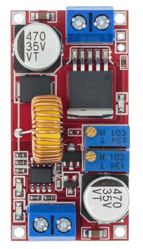
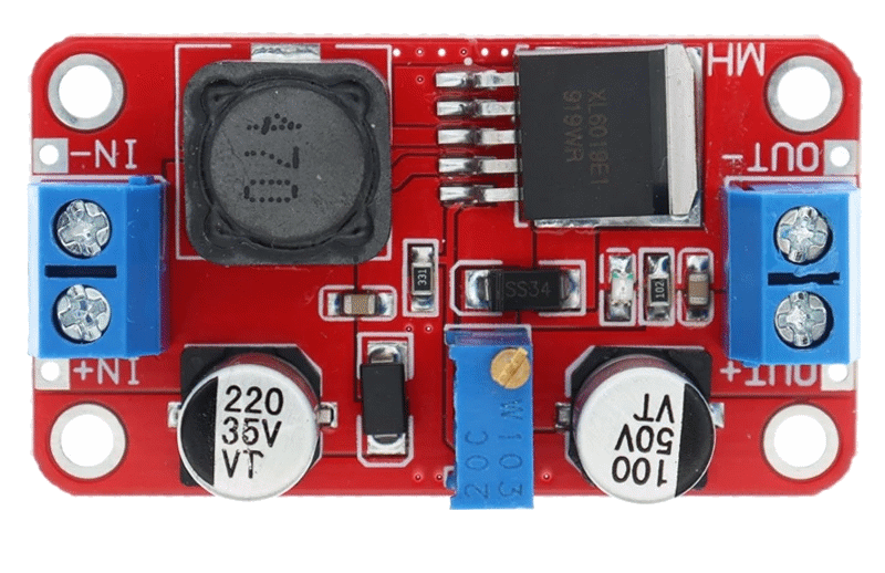

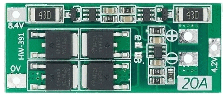
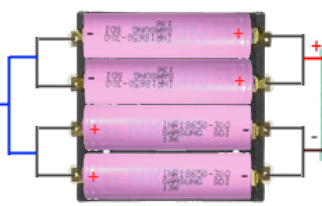
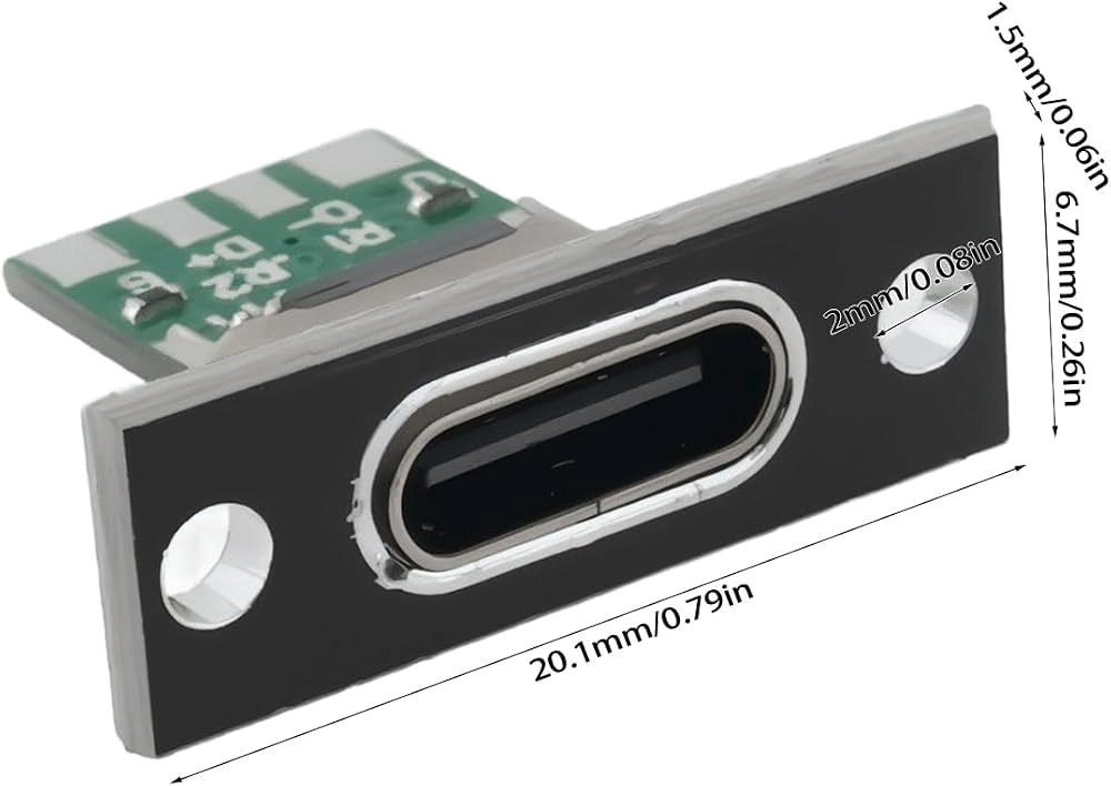
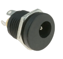
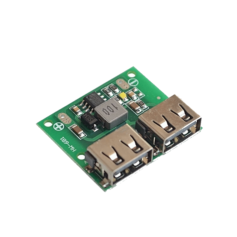
- XH-M350 ฿100
- XL6019 boost converter ฿40
- XL4015 CC/CV charger ฿50
- 5 V USB step-down ฿30
- CM622 2S 20A balanced BMS ฿60
- 4-cell 18650 holder ฿50
- Battery capacity indicator ฿30
- Inline fuse holder ฿10
- SPST switch ฿5
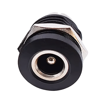
- Panel DC socket + pigtail ฿10
- Wire ฿20
- Enclosure/materials ~฿200+
- 4 × 30Q already owned
- 12 V / 2.5 A adapter already owned
The Battery
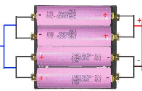
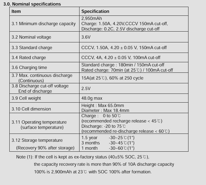
I used four Samsung 30Q 18650 cells in 2S2P.
That works out to roughly:
- 7.2 V nominal
- 8.4 V fully charged
- ~6 Ah
- ~43 Wh nominal
The battery is honestly a bit overkill for this project.
But I already had the cells sitting around from my vaping days, so they were basically free batteries collecting dust. Why not use them?
I'm also a big believer in Murphy's Law, especially when I'm away from home.
That doesn't mean you should go out and buy four expensive cells for your own version.
Calculate your actual load and desired runtime first. And be careful buying popular cells such as the 30Q — the market has plenty of fake and relabelled cells.
Why the Battery Holder?

I deliberately used a 4-cell 18650 holder.
I've seen plenty of DIY projects where people solder directly onto 18650 cells. That's not something I'd recommend to beginners.
Permanent battery packs are normally built using proper welded connections, but I don't own a spot welder.
The holder gives me:
- no soldering directly on the cells
- easy cell replacement
- easy inspection
- no spot welder required
It's not the same thing as a professionally welded battery pack, but for this DIY build I think it's a much better option than putting a hot soldering iron on the cell terminals.
And please don't glue the whole enclosure shut.
You need to be able to inspect the batteries. Put the battery in a cell. Literally.
Don't ask me who sells these battery cells cells. 😆
The Parts
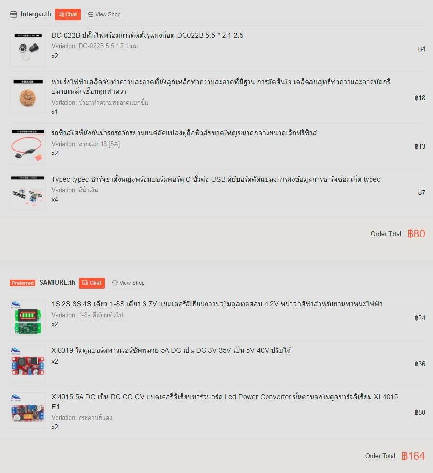
I wanted to keep this cheap, and I already owned some of the important stuff.
Part Cost
XH-M350
฿100
XL6019 boost converter
฿40
XL4015 CC/CV charger
฿50
5 V USB step-down
฿30
CM622 2S 20A balanced BMS
฿60
4-cell 18650 holder
฿50
Battery capacity indicator
฿30
Inline fuse holder
฿10
SPST switch
฿5
Panel DC socket + pigtail
฿10
Wire
฿20
Enclosure/materials
~฿200+
4 × 30Q
already owned
12 V / 2.5 A adapter
already owned
Actual cash spent: about ฿600 (~US$18.46).
The cheap total is mostly because I already had the adapter and batteries. Buying everything new would obviously cost more.
The Charger
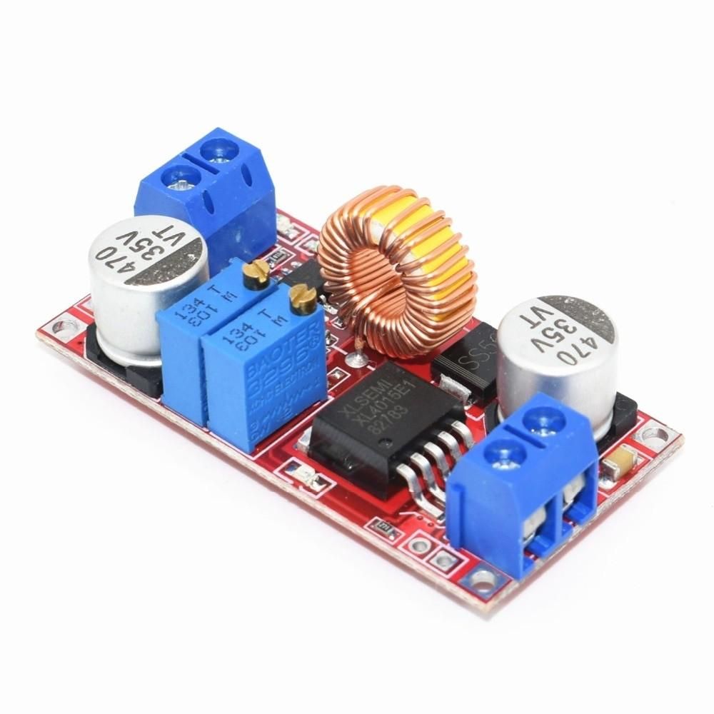

This bit is important.
The battery is a 2S lithium-ion pack, so the charger needs to be set for:
8.4 V CV
and:
1.5 A CC
I don't connect the battery and then start adjusting things.
I power the XL4015 first, use a multimeter, set the voltage to 8.4 V, set the current limit to 1.5 A, and verify the settings before connecting it to the battery/BMS.
Then I check it again.
Because checking twice is cheaper than replacing batteries.
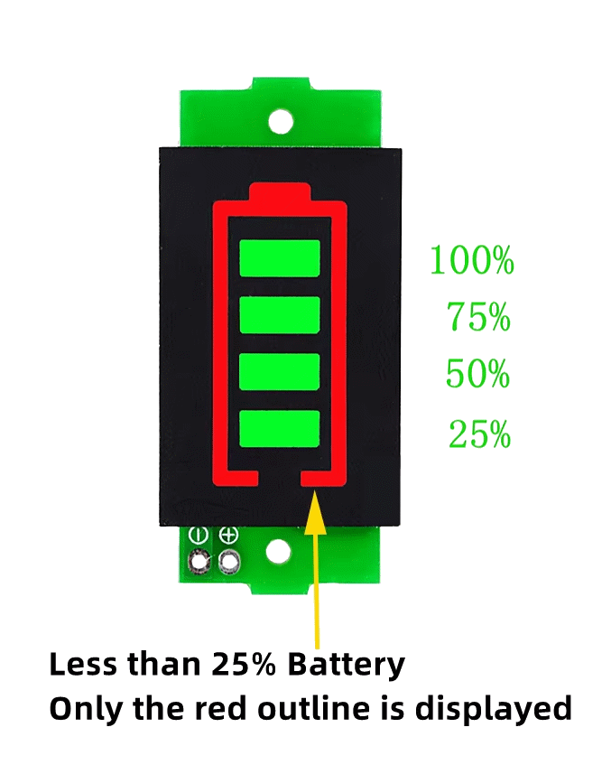
The Battery Gauge
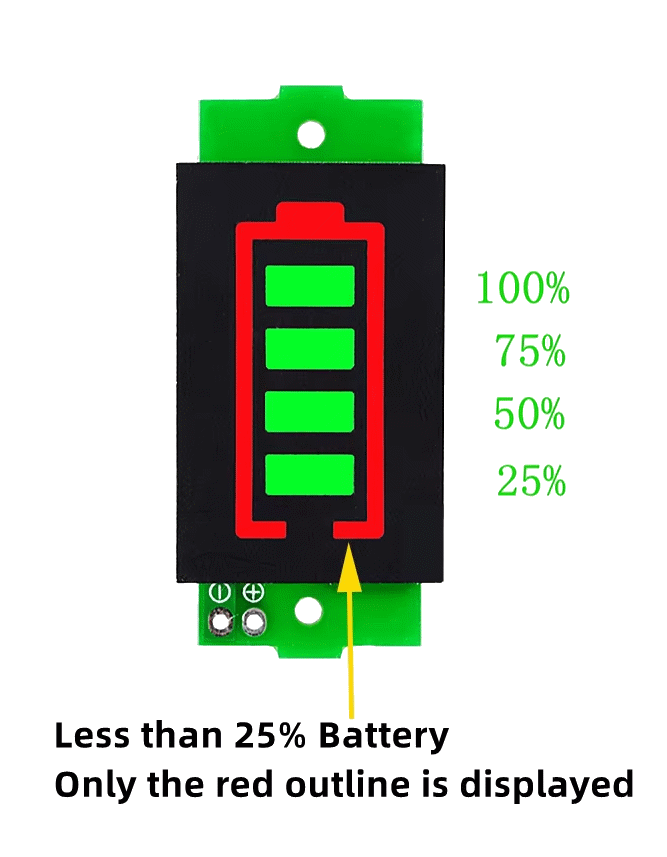
The battery percentage indicator is wired after the battery switch.
So when the switch is OFF, the gauge is disconnected too and isn't sitting there slowly draining the battery.
When the switch is ON, the gauge shows the battery status.
Small detail, but I wanted that behaviour deliberately.
Why the XL6019?
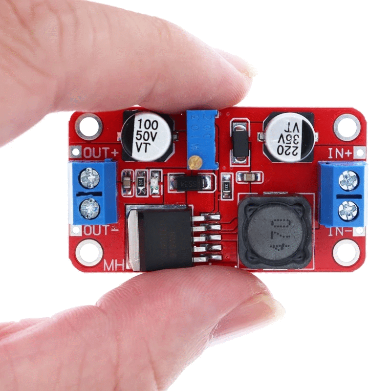
The battery is around 7.2 V, while the router supply is around 12 V.
So the battery cannot go directly to the router.
The XL6019 boosts the battery voltage up to the required ~12 V rail.
I set its output with a multimeter before connecting the router.
One thing I don't blindly trust is the big "5 A" printed on cheap converter listings. The XL6019 datasheet's actual current capability depends on input/output conditions, so I'm treating the converter conservatively rather than assuming it can continuously produce 5 A just because the listing says so.
The XH-M350
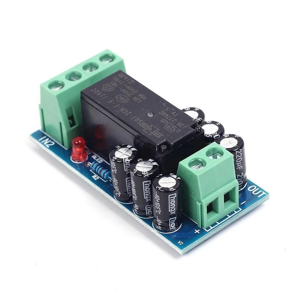
This is the automatic switch that makes it a UPS rather than just a battery and a converter.
Normal power is the preferred source.
The boosted battery supply is the backup.
When mains disappears, the XH-M350 changes over automatically.
I am not going to claim “zero transfer time” or “the router can never notice it” until I properly test that.
That's something I want to measure rather than assume.
The Fuse
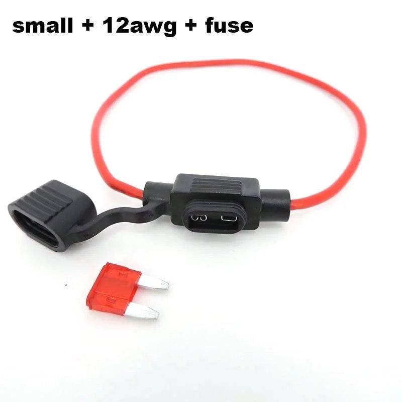
I'm currently using a 5 A fuse.
I originally wanted 7 A but couldn't find one locally, so I used what I could get.
After recalculating the battery-side current and looking at the actual converter limits, I'm keeping the 5 A fuse for now rather than randomly increasing it.
At high output power, a 7 V-ish battery has to supply considerably more current than the 12 V router sees.
For example, even a 24 W output at 85% conversion efficiency would be around 3.9 A at 7.2 V, and battery current rises further as the battery voltage falls.
The important thing is that the fuse is there for fault protection, not to be matched exactly to normal operating current.
I'll measure the actual battery current under load before deciding whether the final fuse should be different.
Runtime

The battery is roughly 43 Wh nominal.
Real usable energy is lower because of converter losses, voltage drop, BMS cutoff, wiring, connectors, etc.
Using an illustrative ~35 Wh usable-energy assumption, the estimated runtime looks like the graph.
These are estimates, not measured results.
And I actually think the simple load estimates above are conservative for my normal use, because when I'm travelling the router traffic is usually pretty light.
The proper next step is to measure the actual power consumption and do a timed battery test.