A Drop-in DIY Upgrade for My (and Other) DIY "CO2 Laser Cutter 40W With Arduino" Project.
by Venkes in Workshop > Laser Cutting
1121 Views, 7 Favorites, 0 Comments
A Drop-in DIY Upgrade for My (and Other) DIY "CO2 Laser Cutter 40W With Arduino" Project.


This Instructable is an easy-to-build, drop-in upgrade for my "CO2 Laser Cutter 40W With Arduino" Instructable. But, It can also be used for a new build or, with minor modifications, for other cutters as well!
After using my DIY laser cutter/engraver for a few years (see my other Instructable), I noticed some issues with accuracy and play between parts. So, I came up with the idea to make a new, sturdier, XY-frame that I can pick up and drop in as a whole! This is in contrast to how I made the previous one, where I built the frame directly inside the housing.
On the foto's you see the old one (with orange 3D printed parts) and the new one (with the white 3D printed parts)!
The old one has an engaving and cutting area of 200mm x 290mm.The engraving and cutting area is now 220mm x 330mm!
This upgrade Instructable is based on my current engraver, which has the following specifications:
Beam height: 156 mm
Beam distance from the left side: 55mm
Cabinet space where the XY-frame is situated: width, depth, height: 550 mm x 420 mm x 208 mm.
I was fortunate that all the rails and 2020 profiles were precisely the right dimensions, so I didn’t have to adjust their lengths! The 25cm x 35cm honeycomb frame fits perfectly as well!
To make this frame fit into other enclosures, the length of the various profiles and belts need to be adjusted. The height can be modified by adapting the design of the foot supports before 3D printing them! See step 6!
Supplies





What I have bought and used:
All available by Amazon!
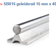
2x SBR16 rail, 400mm
2x SBR16UU slider block
3x 2020 V-slot profile, 500mm
1x gantry (for V-slot 2020 profile) 50mm x 50mm, 6mm thick
1x GT2 pulley belt set 5mm (needed: 2 pulley's, 3 idlers, 2 belt clamp blocks, a few meters of belt)
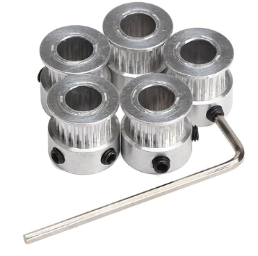
1x set of pulley's 8mm (needed 3 pulley's)
2x Sienoc 8mm bearings, hole distance 37mm
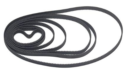
1x set of GT2 closed belts. I wasn’t sure which belt I needed, so I ordered a set. It turns out that I needed a 112mm belt.
2x WJMY limit switch (the same a had in the old one)
1x E-series Nema 17 stepper motor for the X-axis (slightly shorter and lighter than standard Nema 17 steppers).
Aliexpress:
1x second mirror mount (replacement for the old one)
1x laserhead D12 (replacement for the old one)
Enough T-nuts (the ones that can be inserted afterwards), slider nuts (the ones that cannot be inserted afterwards), M5 hex bolts (10mm), and, of course, enough washers. Also, a few M5 hex bolts (10mm) with a lower-profile bolt head.
3x M5 Allan screws (30mm) + 3 Nylock nuts. (for the free-run pulleys of the belt tensioners)
4x M5 Allan screws (20mm) + 4 Nylock nuts. (for the drive-axel bearings)
3x M4 (30mm) hex bolts and nuts (for the belt tensioners)
What I already have in my possession:
1x Nema 17 stepper for the y-axis (normal size)
2x 8825 stepper drivers
one piece of 8mm, 400mm long, steel rod. This is used for driving the Y-axis,
The first mirror mount (the one left, next to the laser tube, which I left in place) remained untouched.
Mirrors and lens
Cable chains
And all other parts wich are used for the old one like the laser tube, LPS, Arduino etc...
All 3D-printed parts were printed on my Creality K1 using Creality Hyper Series filament, with the following settings:
0.4mm height,
3 wall lines, top layers and 3 bottom layers,
75% infill
300 mm/s printspeed
220C printing temperature
I have tried to minimize the need for supports by not combining certain parts and positioning the parts in the most optimal orientation.
Design


In the first step, I designed as much as possible in Tinkercad. This was very useful to check if the parts would fit. In the photo, you see a preliminary stage of the design process. Notice that the 2040 profile is not used at all in the final product!
In the other photo, you can see almost all the printed parts. The gantry plate on the left was not printed; instead, I cut it out of 7.8mm acrylic. However, if you don’t have access to a laser cutter, you can use the STL file to print it.
As a "just-in-case-you-need-them" thought, I made 12 holes on the edges of the gantry plate and tapped M4 threads into them, so you can bolt things to it later if needed.
Downloads
Bolting the SBR16 Rail Onto the 2020 Profiles and Attach the Gantry


Bolt the SBR16 rails onto the 2020 profiles like on photo 1.The distance between the two SBR16 rails must be exactly 415mm, no more. Otherwise, there won’t be enough room to fit all the parts on the X-axis profile!
This first construction step is the foundation, so it is important that everything is square and the rails are parallel. The X-axis has not yet been secured at this stage.
At this stage, you can also fit the gantry onto the X-axis 2020 profile and get rid of any play, ensuring that it runs fairly smoothly.
When you are satisfied with the gantry, you can mount the printhead onto the gantry plate, and then attach the gantry plate to the gantry.
Right End Part of the X-axis

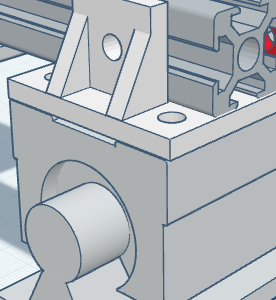

You need to print two 2020 mounting plates!
Place the slider blocks with the hole on the side, facing inward, so you can access it after buiding it in the cabinet, if nececary.
When you are certain that everything is square and parallel, you can loosely bolt the 2020 profile with the 2020 mounting plates onto the slider blocks and check if everything moves smoothly and stays square by moving the X-axis back and forth during assembly. Once confirmed, you can carefully fasten the bolts one by one onto the slider blocks, checking in between to ensure that everything continues to move smoothly. See the video.
Check for any play in the slider blocks and eliminate it by adjusting the screw in the hole on the side, facing inward. This is different from photo 3, where the hole is facing outward. I later changed this to face inward!
Left End of the X-axis
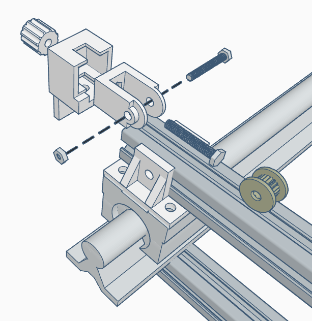
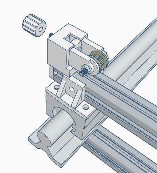
Secure part 1 of the tensioner with a low-head bolt to ensure that part 2 can move in and out freely, and with an other screw to the end face of the 2020 frame. To do that, use a self-tapping screw or tap threads into the end face.
The knob has an embedded M4 nut, which must be printed with a pause at the correct height to allow the nut to be inserted. Search the internet for instructions on how to do that for your printer.
A M4 (30mm) hex bolt goes trough part 1, part 2, and to the knob.
The free-run pulley is secured with an M5 (30mm) Allen screw and a Nylock nut. Do not overtighten; the pulley must spin freely without resistance. Use the pulley washers to position the pulley nicely in the center.
The X-axis Motor
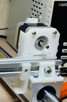
Attach the motor holder to the 2020 profile as shown. The holder in the photo is a preliminary version, without an attachment bar for a cable chain. The belt mount plate, left, underneith, will be added in a later step.
Foot Supports


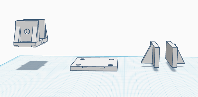
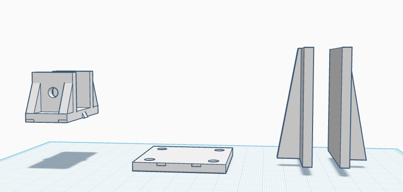
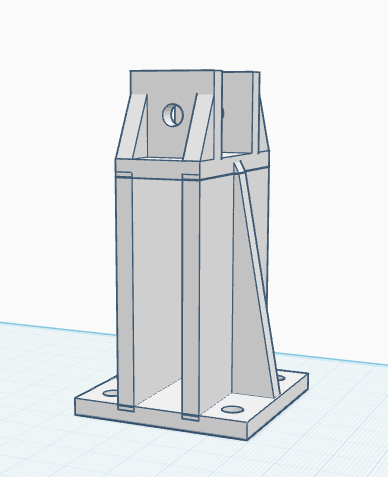
Attach the four foot supports with 2 bolts per foot on the 2020 profile as shown. On photo 1 you can see where I put them.
You probably cannot modify the STL file via ungrouping it. If you need to alter the height of the supports, you can do it like this, in Tinkercad:
- Make 2 copies of the model.
- Create and position 4 see-through blocks as shown in photo 2.
- Group each part separately, as shown in photo 3.
- Adjust the height of the stem (an exaggerated height difference is shown in photo 4 for clarity).
- Align the parts and position the top section at the correct height, photo 5.
- Group everything together and print.
Downloads
Attach 2nd Mirror Holder Mount and the Mirror Holder to the Mount
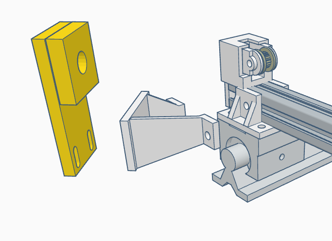
.png)

Just like in the photo!
First, tap M5 threads into the holes of the mirror holder mount (the holes used to secure the mirror holder) and attach the mirror holder mount to the 2020 profile.
It's now possible to roughly align the mirrors using a red laser module or pointer. This is very helpful when the frame is assembled, as it makes the final alignment with the CO2 laser much easier! Just place a red laser on the table and make sure the the beam is parallel with the the Y-axis and shines to the second mirror holder, like if it is coming from mirror 1! On photo 3.
Downloads
Attaching the Belt Tensioners


You need to print these 2 times!
Attaching these belt tensioners is similar to step 4. See the photos for reference. In step 4, you’ve already printed the washers!
The Y-axis Drive Axel


First, attach the bearings to the bearing studs, then slide the 8mm axle through both. Don't forget to place a GT2 pulley (with an 8mm hole and fastening screws) and the 112mm closed belt between the two bearings.
Attach both studs with axel as shown in the photo.
Attach on both ends of the axel the other 8mm GT2 pulley's.
Y-axis Belts


Print two belt clamb mounts. Do not attach them right now!
The two belts must be the same length! Start by cutting one belt to size: lay a long enough piece of belt over the pulleys, ensuring the tensioner pulley is turned outward just enough so that the spacer barely fits. Bring the ends together, pull the belt tight, and cut it to a length where it fits precisely on all the teeth of the belt clamp on both sides. Do not fasten it yet!
Next, place the sized belt on the table with the teeth facing up, and lay a new piece of belt next to it to cut it to exactly the same length.
Lay the belt on theire places, be shure to run the belt trough the tensioner, it isn't nececery to lay him over the pully of the drive axel at this point, just lay it beside the pully. Attach the belts with the belt clamps to the belt clamp mounts with exactly the same amount of teeth covered. This way you know that the belts are equal in lenght. Now lay the belts over all the pulleys and attach the belt clamp mounts to the 2020 profile as shown on the photo. Remove some (not all) slack from the belts with the tensioners. Make sure that the belt runs in a straight line across the pulleys and the clamp mount.
To check if the x-axis is square, pull the x-axis towards you to approximately 2 or 3 cm from the front edge and count the exposed teeth between the clamp and the pulley on the belt on both sides, photo 3. The number of teeth must be the same! If the number of teeth differs, you can easily adjust it by shifting one tooth: insert a piece of filament or something similar between the belt and a pulley, then turn the pulley one full revolution while ensuring the piece of filament also makes one revolution. This will shift the belt by one tooth. The best place to do that is on the drive axel where the pulley is totally exposed!
Now tension the belts and check if the slider blocks run smoothly over the rails. If they do not run smoothly, loosen the 2020 mounting plate on the left side. This will create enough room for the mounting plate to settle when you move the x-axis back and forth. Once you are satisfied, tighten all the screws again. And maybe run the rough mirror allignment of step 7 once again!
Downloads
Y-axis Motor

Attach the motor mount and the motor as shown in the photo's, using 4 bolts to secure it to the 2020 profile, of course (not just two as shown in the photo!). You can adjust the belt tension using the slotted holes
Downloads
X-axis Belt


Make sure the tensioner is in its loosest position.
Cut roughly the required length of belt from the roll and lay it over the pulleys and through the holes in the gantry plate. This is easier if you slightly loosen the gantry plate. Remove any slack and secure the belt ends with zip ties, as shown in the photo. Fasten the gantry plate.
Now you should have something similar to what is shown in photo 2, but now with cable chain mounts!
Limit Switches

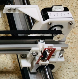
Attach the limit switches as shown in the photos, using the limit switch mounts.
In this step, I am assuming a home position at the top right!
The Final Step Outside the Cabinet

The final step outside the cabinet is to attach the X-axis cable chain, as shown in the photo! The photo also shows the state of the setup before installing it in the enclosure.
Building It in the Cabinet and Allign the Mirrors

Below are a few steps where an unprotected laser will be in use. While I assume that if you’re reading this Instructable, you are familiar with how to handle CO2 lasers, I still want to emphasize this warning:
**************************************************************************************************************************************
NEVER, EVER DO THIS WITHOUT SAFETY GOGGLES! USE GOGGLES THAT ARE DESIGNED TO BLOCK THIS TYPE OF LASER LIGHT (10.6 µm)!
While laser light, whether direct or even reflected, in the visible spectrum can damage your retina, the laser light from a CO2 laser can destroy your cornea. That’s definitely not something you want to experience!
So please be very very carefull and allway be aware of what you are doing!
***************************************************************************************************************************************
Carefully determine the location and orientation for the setup to be installed! Put on your safety goggles, switch on your laser, and apply painter's tape to mirror holder two (the one that moves back and forth). Push the 2020 profile to the back and briefly fire the laser with as little power as possible. Now, pull the 2020 profile towards you and fire the laser again. Slide the frame and repeat the previous steps until the laser spot lands in the desired position.
When everything is ok, screw the frame to the bottom, if you have a wooden cabinet you can use M4 screw inserts for wood (what I did), like on the photo, or with normal screws.
Now you can attach the motors and switches, adjust the settings of your burner program regarding dimensions, home position, etc., and perform a test run without the laser. Check if everything is functioning correctly, then adjust the laser mirrors.
If you also want to create a cable chain from the sidewall to the X-axis, I’ve included a print file for that as well! If you use this additional mount, you will need to remove the top two screws from the motor and reattach the cable mount to the motor bracket using the same screws.
End
Thank you for checking out my Instructable!
I truly appreciate your interest in my design. If you decide to build it yourself, I hope you enjoy the process as much as I did. Wishing you the best of luck with your build—may it work flawlessly and bring you lots of satisfaction.
Feel free to share your results or any feedback; I’d love to see how it turns out for you!
Happy building!
As a final note: I noticed that the laser head wasn’t at the correct height, so I designed an adapter ring to elevate it to the desired height. If you also need one, you can print the adapter to match your required height.