A Persistence of Vision Rotating Display Controlled by a Raspberry Pi Pico.
by lhm0 in Circuits > Raspberry Pi
1527 Views, 18 Favorites, 0 Comments
A Persistence of Vision Rotating Display Controlled by a Raspberry Pi Pico.


The Rotating Display Pico is a compact disc-sized persistence of vision display that rotates quietly using a CD motor. It features 56 white LEDs which are controlled by a raspberry pi pico. The device can display animated images as well as time and weather data sourced from the internet. It is wirelessly powered and controlled via a user-friendly web user interface. The device has been developed with a focus on reducing the number of components and thus cost, it only uses off-the-shelf components, and is easy to assemble.
The Story
The rotating display pico works according to a simple principle: persistance of vision. It is fascinating to watch some flickering LEDs paint images when they move. The idea of this version of the display, which is the third in a row of generations, was to further simplify the design and to reduce complexity, improve image quality, and to allow for the display of animated images.
The development of the device presented some highly interesting engineering challenges. The Raspberry Pi Pico with its powerful programmable IO (PIO) allowed for a new approach to controlling the LEDs. While previous versions of the display used serial shift registers for addressing the LEDs, this model uses fast multiplexing. The approach might be further scalable, for example for a rotating 3D display.
Here are some of the features of the rotating display pico:
* Simple design with few mechanical components
* Complete balancing of the display board to ensure vibration-free operation
* Replicable wireless power supply with printed coils
* Hand solderable PCBs with relatively few off-the-shelf electronics components
* Full control of the device by Raspberry Pi Pico
* fast multiplexing of the LEDs by means of the programmable IO (PIO)
* interlacing for higher resolution and less flickering
* easy to use user interface via a standard web browser
* Retrieval of time and weather data from the internet
* Display of animated GIF images
* Implementation of a file browser for the SD card for uploading image data
* Transparent, object-oriented structure of the Raspberry Pi Pico software
The Operating Modes of the Display
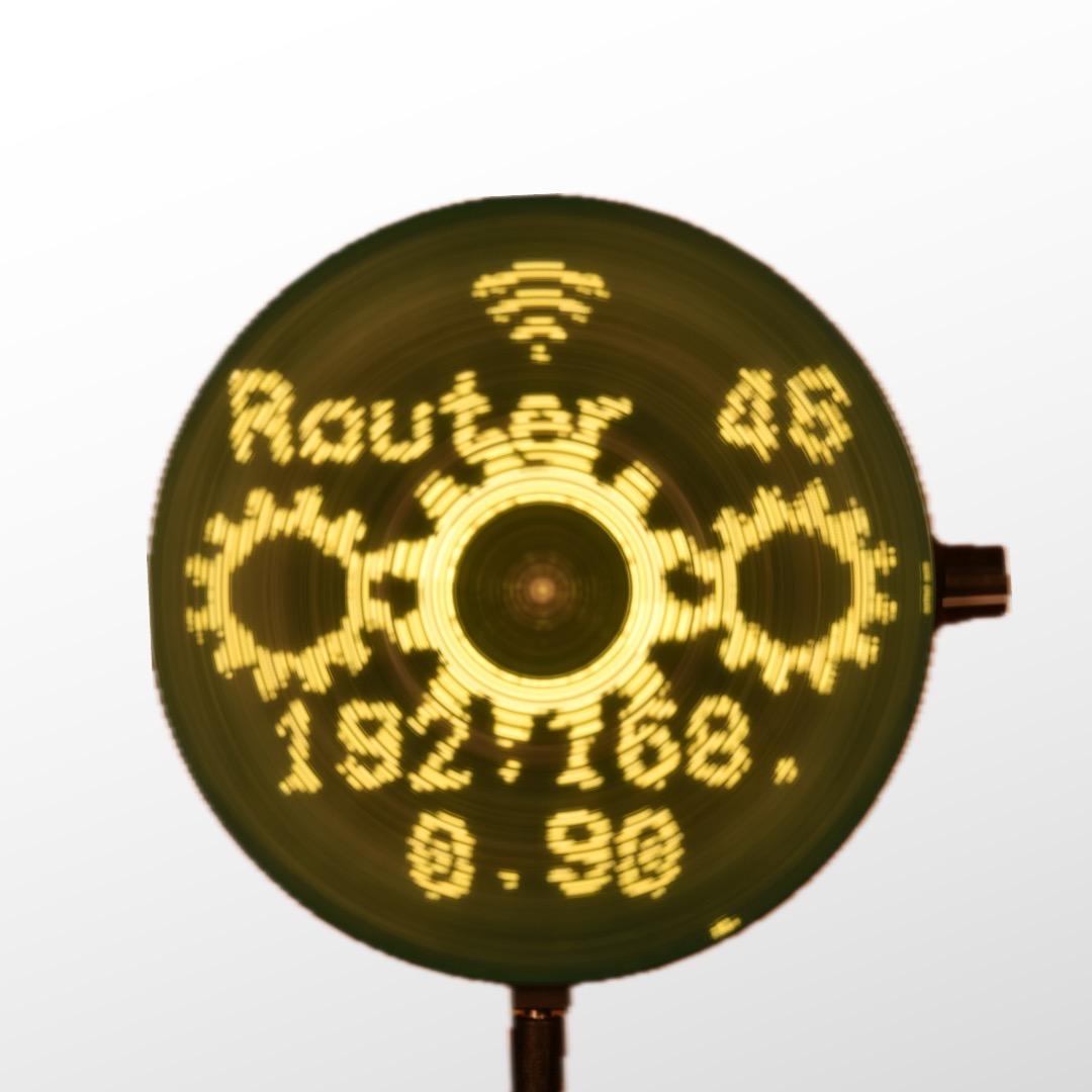



When switched on, the device tries to connect to a known wifi. If no valid wifi credentials are found, the unit will be configured as wifi access point. In this mode, a computer or mobile device can be connected, directly (SSID: RD56m, no password).
Once the wifi connection has been established, the unit will display its IP address on the home page of the device. Enter this address in your web browser. This will load the web user interface and will allow you to configure your local wifi.
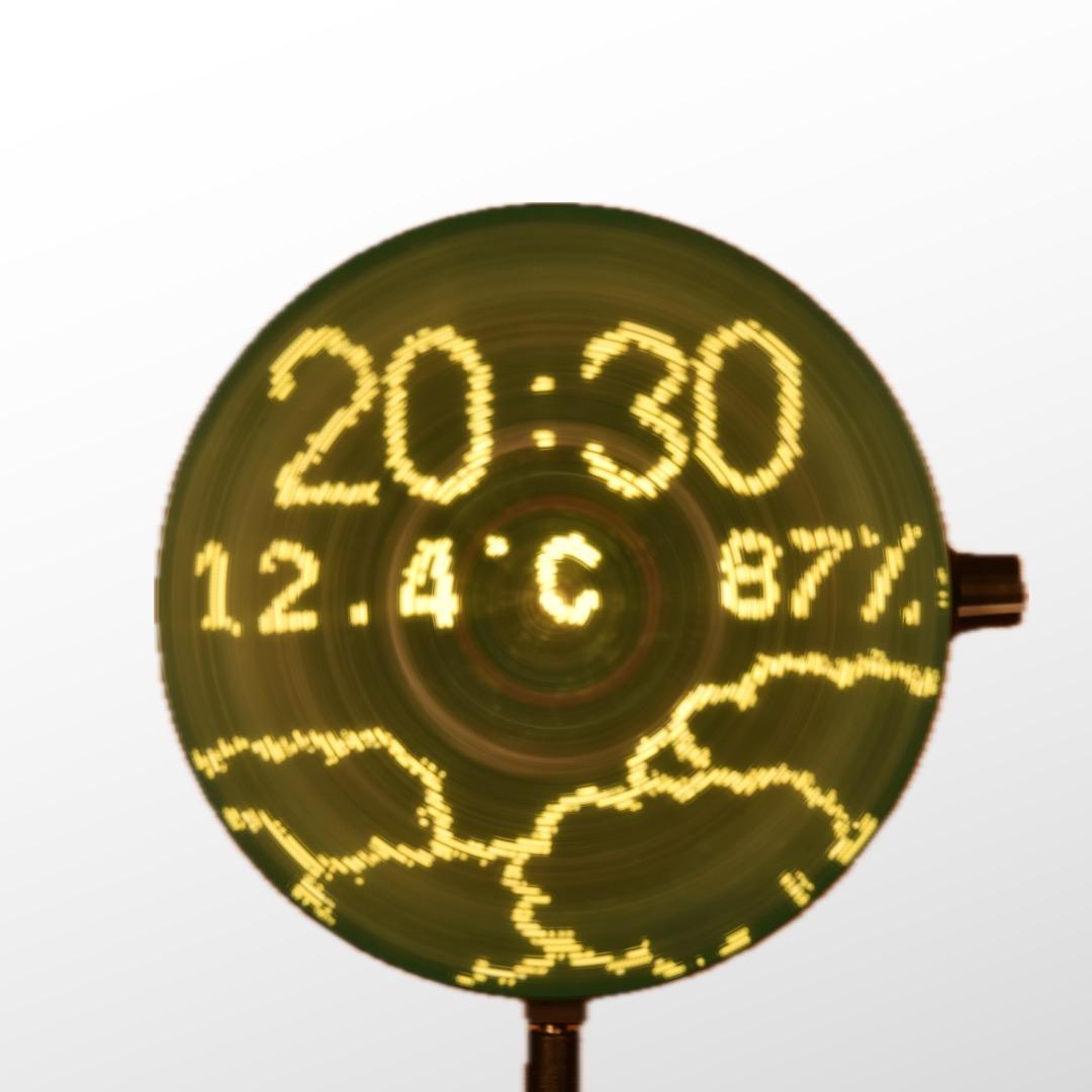
There are several operating modes that display time and weather information. Both in analog clock mode and logo clock mode, images can be displayed in the background. These images might be animated. Images of various formats, including animated GIF images, can be easily uploaded from the user interface and converted into a specific format.
How to Use the Display


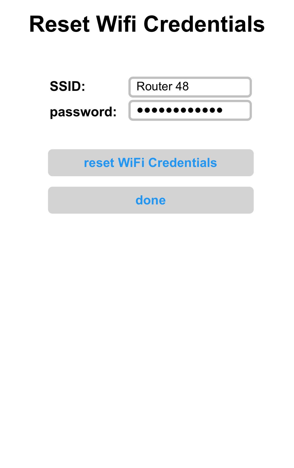

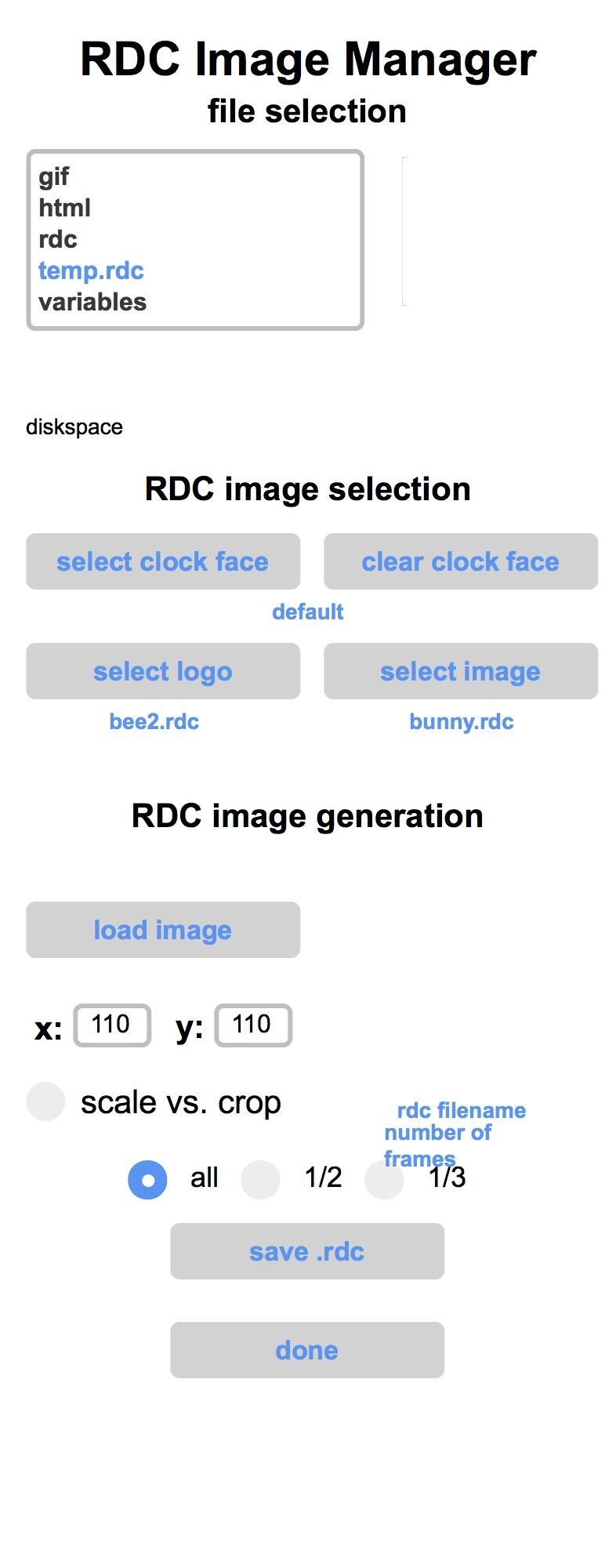

Device operation is managed through a web interface, accessible from any web browser. The interface allows users to select the operating mode, adjust the display brightness, manage login credentials, upload image files to the display, and control image and configuration files through a file manager. The use of the interface is intuitive and self-explanatory.
The Structure of the Device


The device consists of two assemblies: power supply and display. The power supply board is also the base plate, which can either be placed on a flat surface or hung on a wall. A standard CD motor is attached to this board so that the CD tray above the power supply board can accommodate the display assembly. The display board is fixed with two M2 x 6 mm screws. Furthermore, the base plate carries a potentiometer to control the motor speed as well as an on/off switch for the motor.
The display board is equipped with a row of 56 white LEDs. The LED operations are controlled by a Raspberry Pi Pico microcontroller, which also generates the display content, and manages the user interface by means of a Wi-Fi connection. Images (including animated images) can be stored on and loaded from a micro SD card. The access to the Internet allows for the acquisition of time and weather data.
An important requirement for the display board is that the center of mass of the unit is exactly in the middle, on the axis of rotation of the motor. This is the only way to ensure smooth and vibration-free running of the display. To achieve this, the electronic components are arranged largely symmetrically. Residual asymmetries are compensated for by balancing weights (M3 screws and nuts).
The core of the power supply is a Royer converter for wireless power transfer. The circuit uses very few components, but its coils are quite complex. In order to ensure reliability and reproducibility of the device, the coils (bifilar primary coil, coupling coil, secondary coil) are implemented as a printed circuits.
How to Assemble the Rotating Display Pico




5.1. component supply
The parts list and all necessary documentation is available on GitHub. The Bill of Material also contains sources and corresponding links for purchasing the parts. Most components are off-the-shelf and easily available. However, the only critical component might be the LEDs, as they need to have very high brightness (I have used 1800 mCd). I purchased the LEDs from this source.
The production files of the PCBs (Gerber files) are included in my GitHub repository. Any PCB manufacturer can make boards out of those. I used JLCPCB for manufacturing, but there are many other high quality suppliers as well.
Remark: I have made both black and green versions of the PCB. The photos are mixed.
5.2. the motor assembly
Use fast curing two component epoxy resin to glue the CD motor to the carrier plate. Furthermore, carefully glue two M2 nuts to the CD tray auxilliary plate, without contaminating the threats.
Use double sided tape to attache the auxilliary plate with the two M2 nuts to the back of the CD tray. By means of two M2 screws you can make sure the plate is in the right position.
Solder the two wires of the motor to the carrier plate (red = "+").
5.3. the power supply board
Solder all the components to the power supply board, as shown in the photos. Further details can be obtained from the KiCad files in the GitHub repository. Then, use 4 pin connectors to attach the motor assembly to the power supply board. Use M3 screws with a flat head to screw the 20 mm bolts to the pcb. Finally, use fast curing epoxy resin to glue rubber bumpers onto the ends of the bolts. Insert the 6 mm magnet into the respective hole in the power supply board. The orientation of the magnet is critical. To find out, which side to but upwards, attach the magnet preliminary with a piece of adhesive tape, first. The only way to check orientation is trial and error.
5.4 the display board
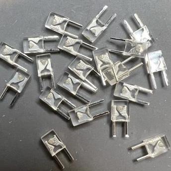
Fit all the electronics components to the display pcb. Start with the LEDs. It is MOST critical to insert the LEDs with the correct orientation, as a mistake can almost not be corrected (I made that mistake…). Double and triple check the correct orientation. Use the above photo to identify the cathode of the LEDs. Note the print „cathode“ and „anode“ on the pcb. The squared pad is the cathode. Note that the orientation of the LEDs flips in the middle of the disk.
If you want to use SMD MOSFETs, continue with those. I usually use cross-over tweezers to hold the component, while soldering. The easier choice are the threaded MOSFETs (BS250), but they are considerably more expensive and more difficult to find.
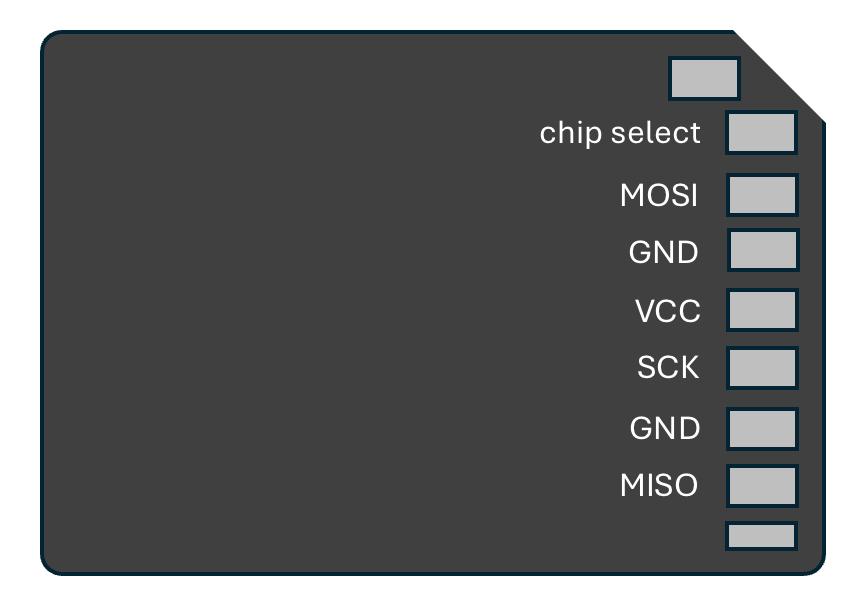
Next, insert the SD-card slot. If you use the SMD component, first attach the housing, then solder the contacts. Do not hesitate to use lots of solder first, then remove surplus solder with a desoldering pump and/or desolder braid. An easier alternative is to use a SD to micro SD adapter. Check the correct orientation of the adapter in the wiring diagram. Wires need to be soldered to the adapter and then need to be connected to the pcb pads (position it vertically to the pcb at first). Then bend the adapter such that the contacts are facing the pcb. Unfortunately, this is the only way to allow for the insertion of the card. Glue the adapter to the pcb.
All other components are easy to solder.
Use 6 pins to attach the secondary coil pcb to the back of the display board. Make sure, the two boards are connected and soldered tensionlessly, as the relative position between the two boards needs to be as precise as possible. Finally, use two M2 x 6 screws to attach the display pcb to the power supply assembly.
Uploading the Software and Necessary Data to the Microcontroller
The nice thing about the Raspberry Pi Pico is that you do not need to be familiar with the software development tools in order to install the software. Just connect the Raspberry Pi Pico W with a micro USB cable with your computer. Your file browser will open a new drive „raspberry pi“. Drag and drop the file „firmware.uf2“ to this drive. You can find this file in the GitHub repository. The computer will automatically upload the file,
Finally, you need to copy some folders and files to a micro SD card. First, properly formate the SD card. You might want to use the formatter of the SD association. Possibly, the on-board formatting routine of your PC serves as well. Then navigate to the data directory of the repository (RDpico_software > data). Copy the four folders (gif, html, images, variables) to the SD card. Insert the micro SD card into the card slot of the display board.
Setup the Rotating Display Pico
Once the software is uploaded to the Raspberry Pi Pico and the micro SD card with the necessary data is installed, restart the display by pulling the power plug and reconnecting again. Switch on the motor. Now, the system should run properly and display the home screen with the wifi information. If there is no stable image, turn around the magnet.
Use your computer to connect to the wifi (SSID RD56m, no password) and start a web browser. Enter the displayed IP address in the address line of the browser. The user interface page will be loaded. You can edit the wifi credentials by clicking on the “config wifi” button of the user interface. Enter the data for your local wifi, click on “done”. Re-start the display. Now, the device will connect with your local wifi and will display it’s new IP address.
If you would like to use the weather clock mode, you need to configure the access information to openweathermap.org. In order to do so, you need to register and subscribe to the “Current Weather Data” Service, which is free of charge. The platform will provide an API-key, which you need to copy to the UI of the Rotating Color Display.
Uploading images, converting them, and downscaling the resolution to 110x110 pixels can be done with the “RDC image manager” page of the user interface. The software can deal with a wide range of image formats and resolution, including animated GIF images. As a last step, select an .RDC image in the selection box by long clicking on the entry. Assign the image to the analog clock, the logo clock, or the image mode by clicking on the respective button.