A Quartz Crystal Color Chandelier
by vchaney in Workshop > Lighting
230 Views, 1 Favorites, 0 Comments
A Quartz Crystal Color Chandelier
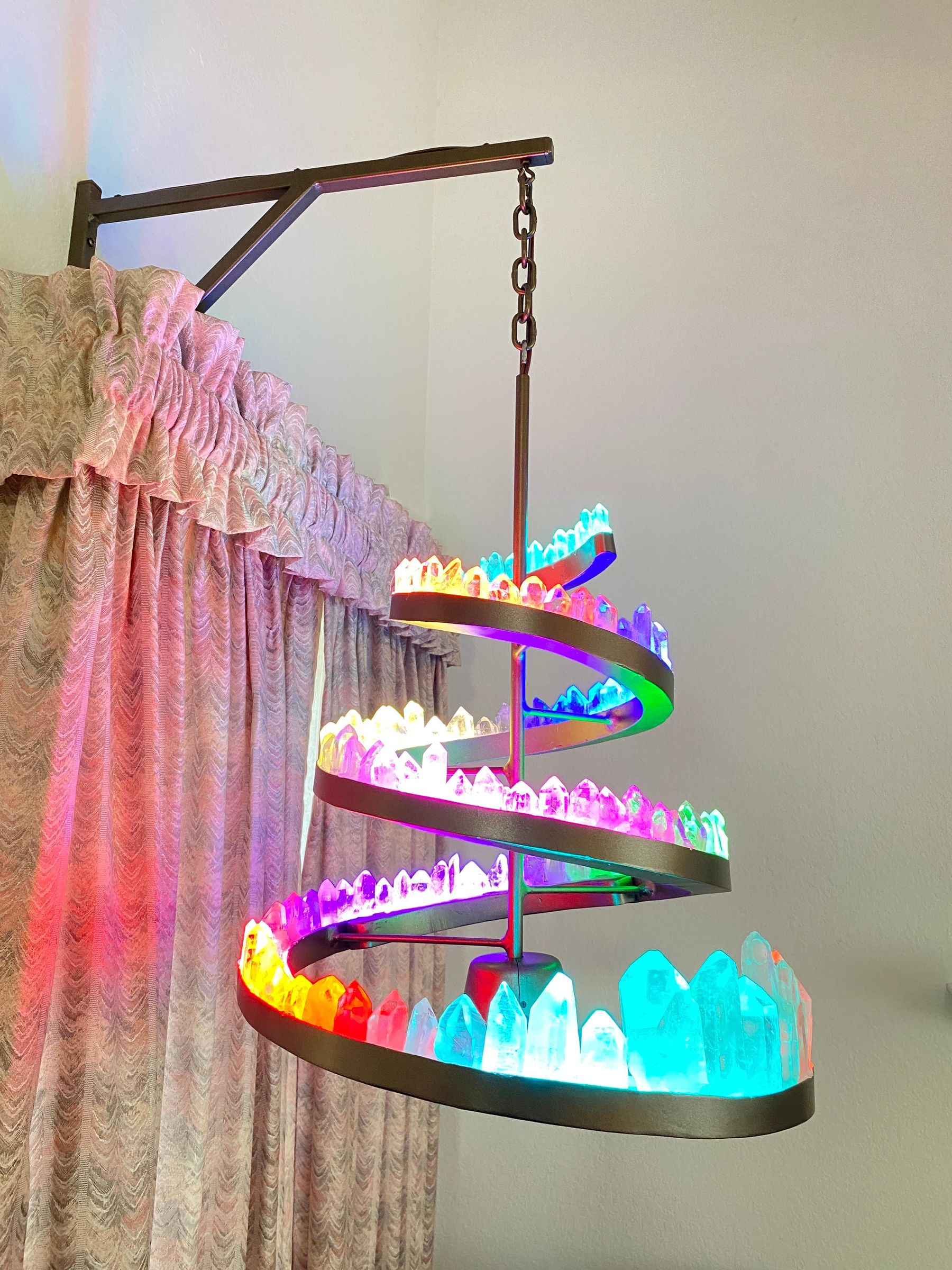
Have you ever dreamed of creating a stunning piece of art that not only illuminates your space but also captivates your imagination? Imagine a chandelier adorned with genuine quartz crystals, shining brightly with a spectrum of colors and dynamic light patterns. This guide will take you through the intricate process of constructing your very own crystal chandelier, a masterpiece that merges elegance with innovative technology. Prepare to unleash your creativity and embark on a journey that combines craftsmanship, engineering, art, and the natural beauty of crystals.
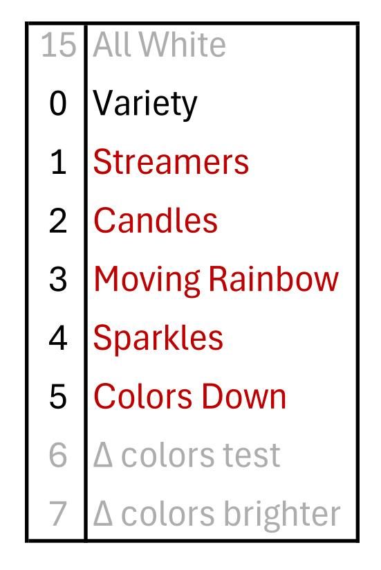
Quartz crystals are mounted into a spiral channel and lit from underneath with DotStar LEDs. The LEDs are controlled with a Teensy 4.0 microcontroller, and in addition to being able to light them all with a single color, it can make moving groups of colors, moving rainbows, flickering lights that are like candle lights, and twinkling colors.
The Crystals
I used 132 quartz crystals, which I got from Vacaville Rock Shop. They came in bags, and I bought a bunch and picked out the ones that I liked the best. They come in different sizes, and some are very clear (best) and some are smoky (not so good). I got some bigger ones about 1.5 inches in diameter, and then small ones ranging from 1.25 down to 3/4 inch in diameter. I went there and picked them out, but a phone call would enable you to tell them what you want and have them shipped to you. They say that they are the biggest rock shop in the world. I don’t know if it is true, but seeing the size of the store it is very believable. You can also buy the crystals at Amazon, and other places as well. I bought twice as many as I thought that I would need, so that I could pick and choose the prettiest ones.
Making the Metal Structure
The framework that holds it all is made of 16-gauge sheet steel. I started with a 24” x 36” sheet, and it gave me enough to cut all the pieces with a little left over. I used a jig saw (saber saw) with a 32 TPI metal cutting blade to cut them out. Brush a narrow line of cutting oil (or other oil) onto the line to be cut before cutting to preserve the blade.
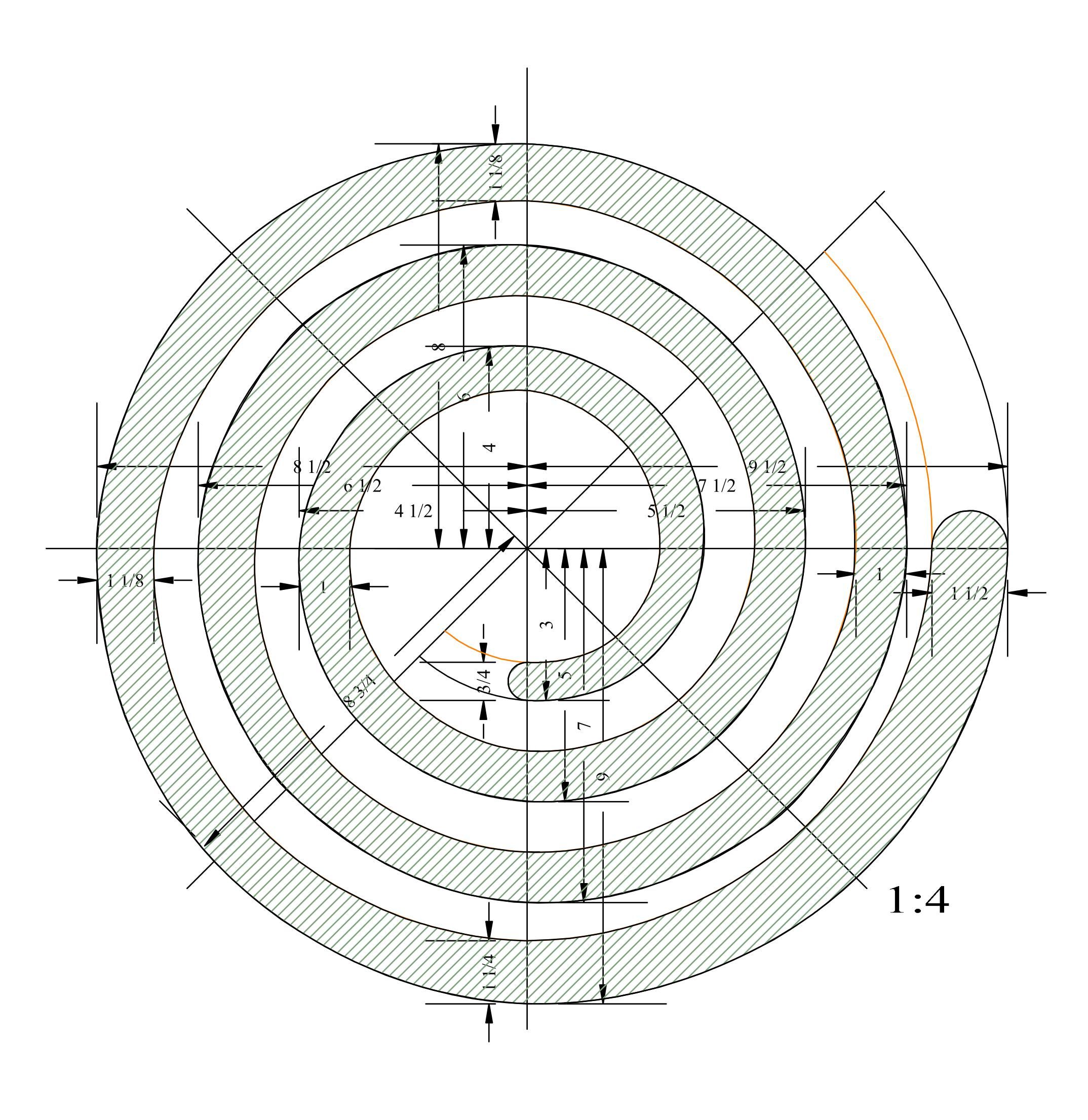
First, cut out the spiral. The outer edge of the spiral starts 9 ½” from the center, and spirals in 2 inches horizontally per turn. I drew mine on the metal, but I also created a drawing of it (Figure 1), and if you have it printed 4 times the size of the drawing at your local copy store you will have a full-sized template. The channel is widest at the bottom and gets narrower to accommodate small crystals as it goes up. You may wish to use different widths, depending on the size of crystals you acquire. You should have the crystals before you cut out the spiral to get the correct widths of the spiral at the appropriate positions on the spiral. Keep the outer edge of the spiral like the drawing and adjust the width by adjusting the position of the inner edge. The metal needs to be very clean for good welding, so sanding it with 100 grit angle grinder sanding disks is easiest before bending it, to get off the gray layer that interferes with the weld.
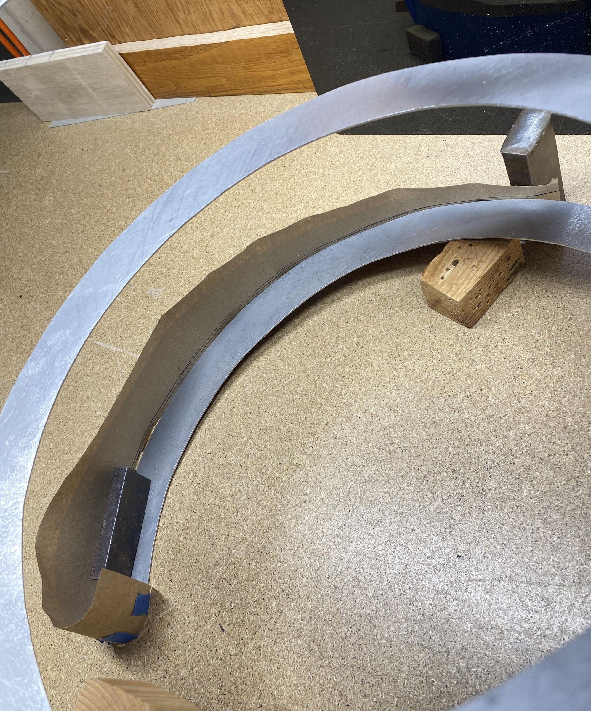
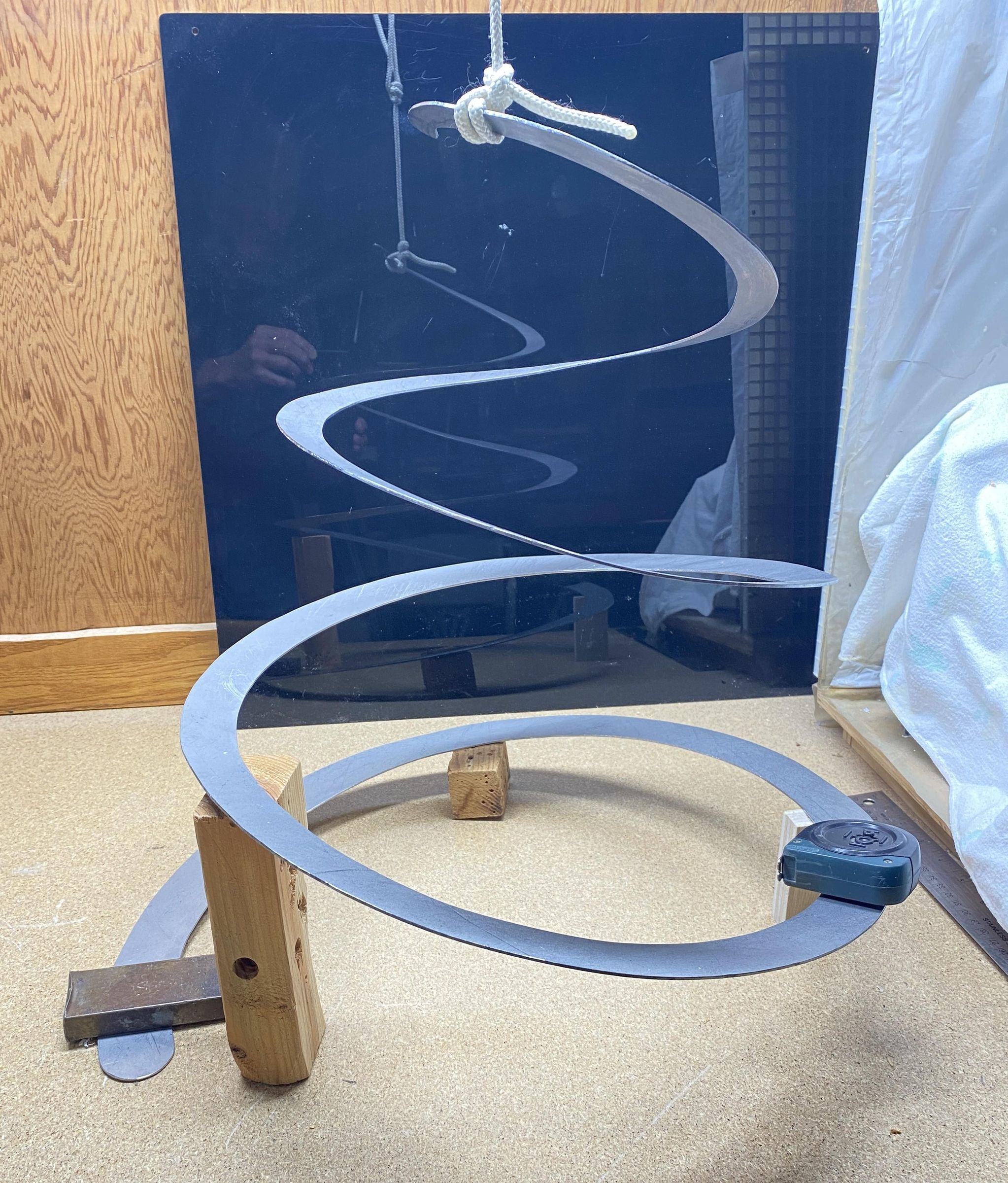
If you stretch the spiral into a spring, it will slope down from the center. Instead, using two sets of pliers curve the metal up at the outside and the inside at the same time, and you will get a spiral whose floor is more level from inside to outside. (Figure 2) I went for 6 vertical inches between each turn of the spiral. Then I used rope to hang the top, and blocks of wood underneath to get it in close to its final position. I wrapped some heavy paper against the outside, to get the shape of the outer side of the channel. (Figure 3) Then I transferred it to the steel and cut out the first piece. I welded this on and then made 24 inch segments, all 1 1/8 inch wide (includes a little extra that overlaps the bottom and will get ground off to be even), welding them on one at a time. Except for the top and bottom pieces, the rest of the pieces are the same shape, with the bottom edge curving up about the same amount on each piece, and the ends are adjusted to fit the previous piece. The top and bottom pieces curve around the ends, so that the joints between those and the inner sides of the channel are more hidden.
I am not a professional welder, and my welds are sometimes less than beautiful. I used brazing instead of welding, The brass brazing rod melted more beautifully without melting the steel. Even so, my welding was not pretty enough, but the application of an angle grinder by both grinding and sanding got it closer, and then a thin layer of Bondo (used for car body work) could be added and shaped, giving it a much more even appearance. With the Bondo, only make a little at a time. It sets fast, and there is not a lot of working time. After a short time, it has an initial set that is much more easily filed and sanded than when it sets completely.
I made my spiral longer than necessary at the top, welded on the outer wall, then laid some rope along the bottom to gauge it to 3 meters, and then trimmed the spiral. The strips of LEDs ended up longer than I figured, so I cut off 5 to have 427 LEDs instead of 432. The code for controlling the strips needs to be adjusted for the number of LEDs by changing the NUM_LEDS constant.
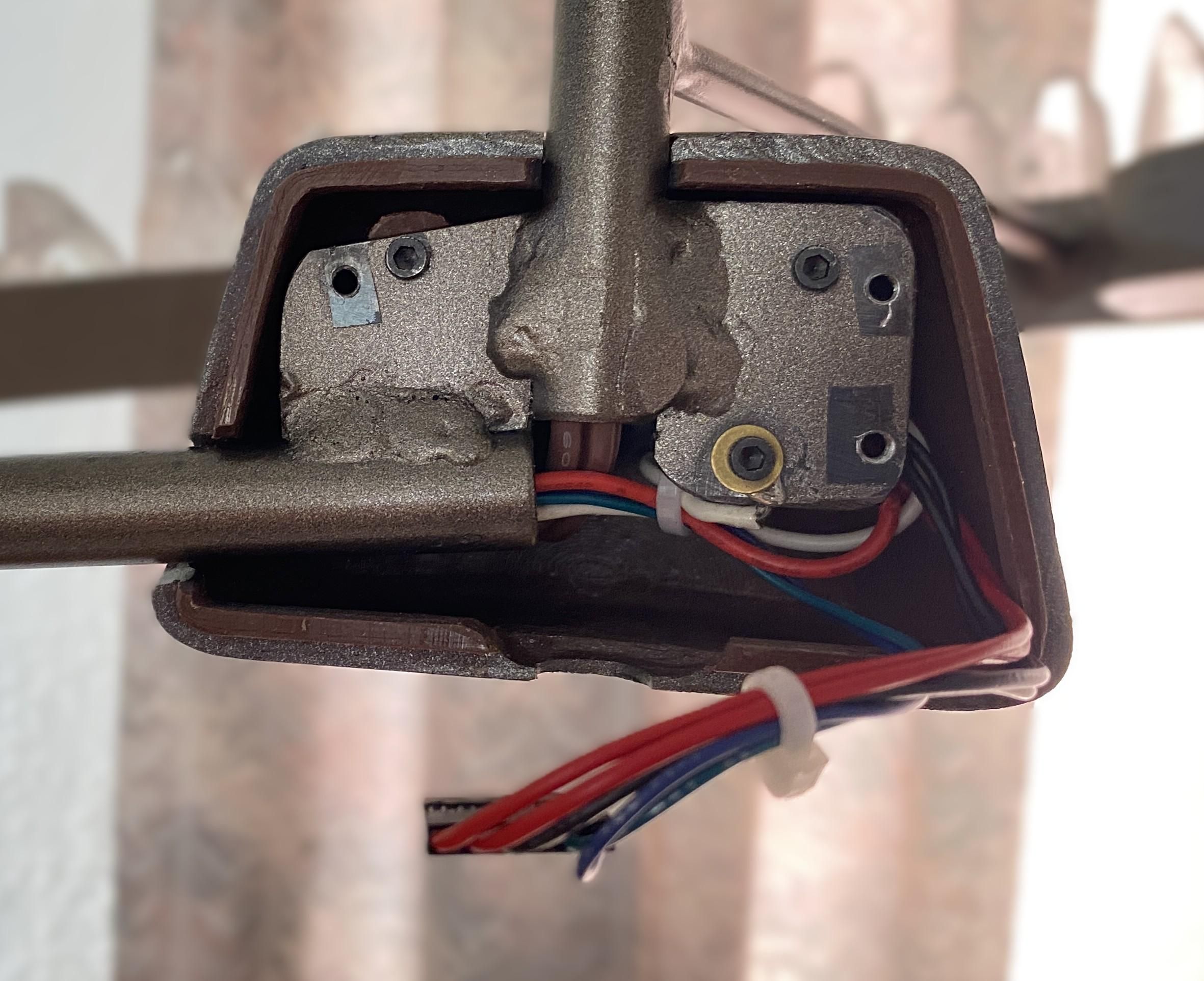
The center tube holds the wire bringing 5 volts from the power supply to the chandelier. At the bottom, another tube connects to the channel holding the LEDs. Then I used 3/16” rod every 120° to support the rest of the channel. Two tabs of 1/8” thick steel connect the two tubes at the bottom and have holes to mount the circuit to the bottom, and to the back cover. (Figure 4) If you drill the holes for mounting the plastic cover at the same dimensions as mine, then it will fit the 3D printed cover (see the circuit holder at base.pdf). The cover is attached with two 4-40 machine screws by holes threaded int the mounting posts inside the cover. Also needed is a hole to connect the electrical ground to the structure.
I made the cover for the electronics by 3D printing it, and the stl file is included with the files. The halves of the cover are fastened together with 2-56 flat head machine screws. A cover could also be made using wooden disks at the top and bottom surrounded by thin sheet metal. Papier mâché could also make a nice cover.
When the framework is complete, now is the time to paint it before adding the rest.
Add the LED Strips
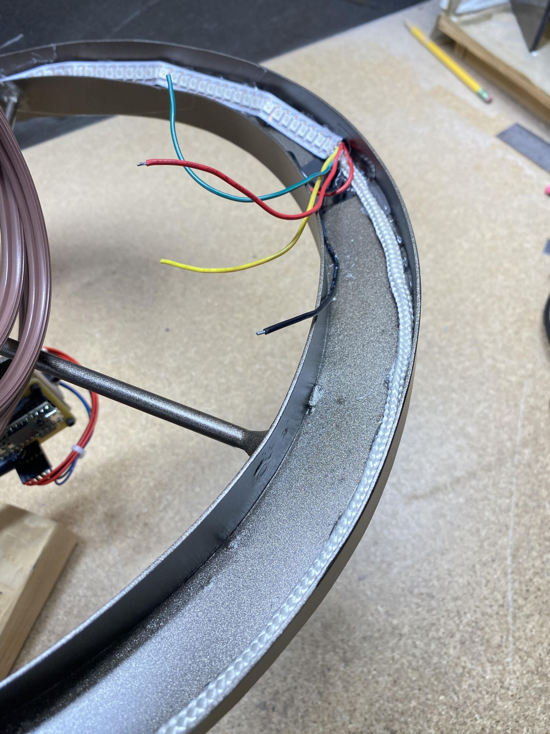
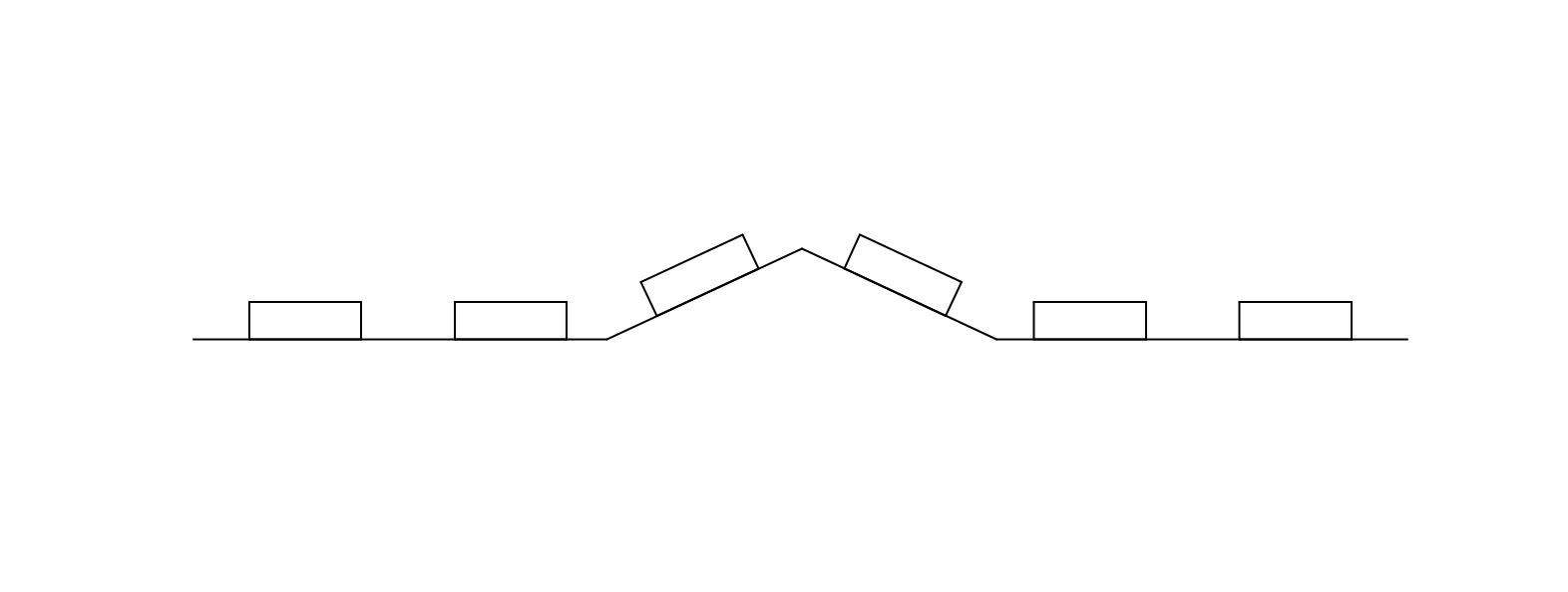
The LED strips are laid at the base of the outer wall of the channel, facing up about 45° from the floor of the channel. (Figure 5) The strips do not really want to bend this way, so by bending the strips a little every 15 LEDs will allow them to face at the correct angle (Figure 6). I glued a piece of ¼” thick rope to the outer corner of the channel and then dots of hot glue attaches the strips onto that. Try not to get the hot glue directly under the LEDs to avoid overheating them. The strips are wired in series. You must connect the data and clock lines between each strip, but the strips can’t handle enough current for the 5V and ground power wires to get to the lights at the end if they are only connected end-to-end. So, the power wires are connected between each strip, and power is connected also to the junctions between each strip and to the far end of the whole chain of strips. I ran all the wires along the base of the inner wall, hot gluing them into place. I got one strip into place and tested it with the test section of my programs, making sure the number of LEDs is set correctly for the number of strips being tested.
Make a Reflective Bottom
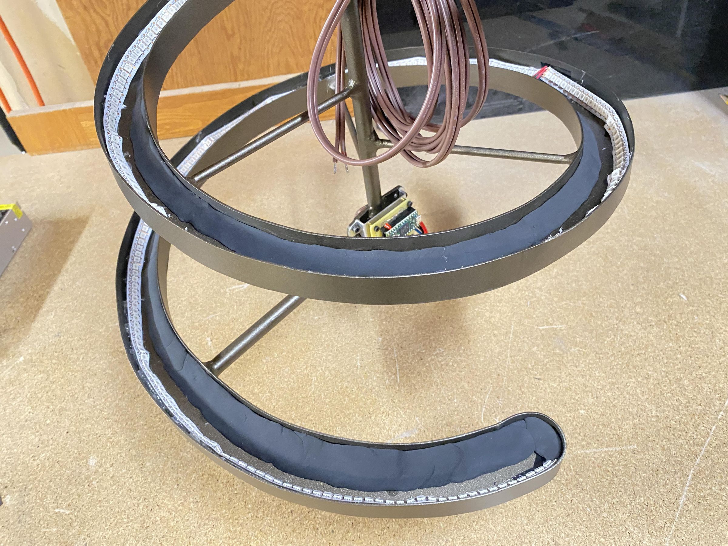
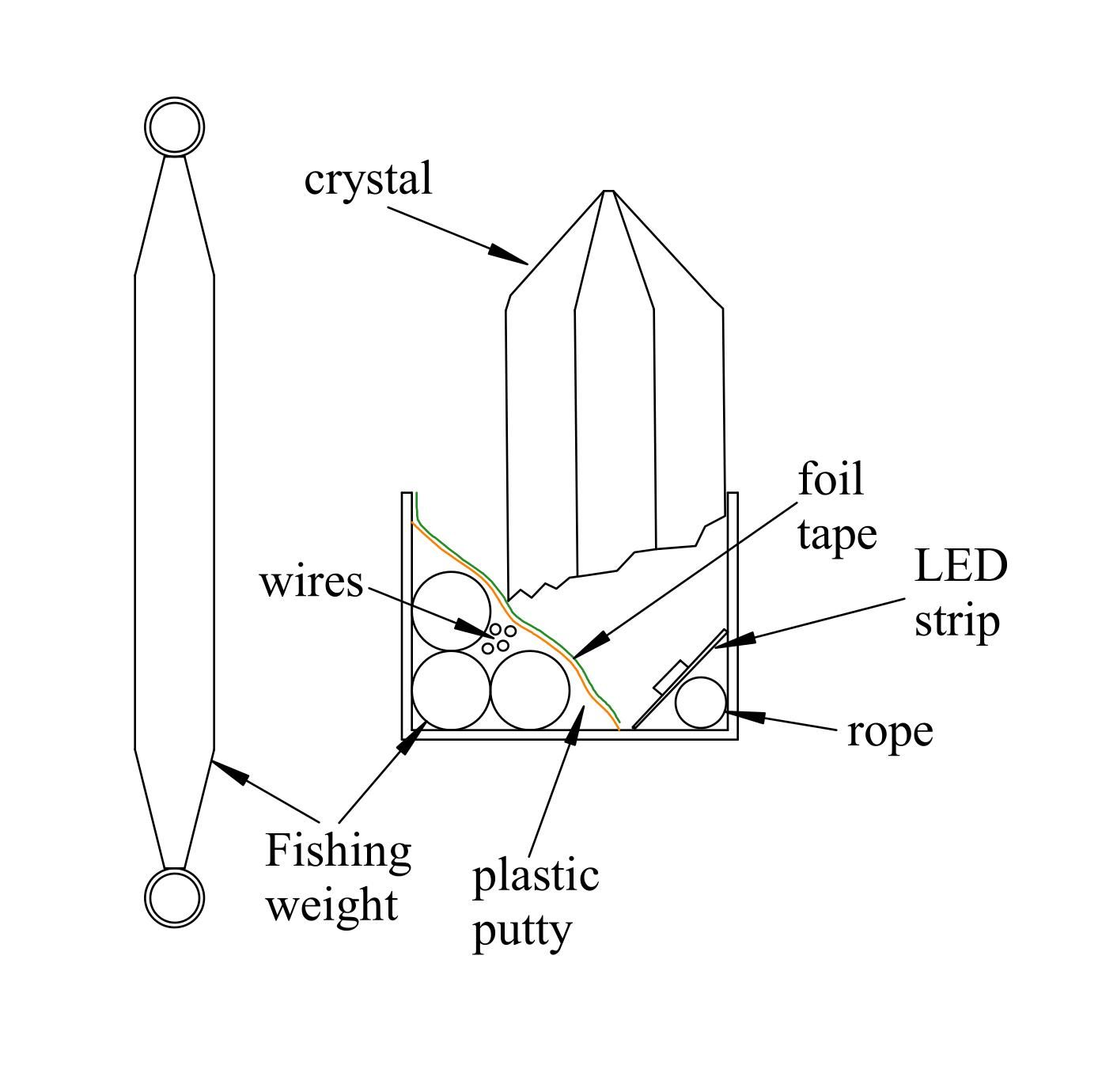
Once the LEDs and the wiring were in place, I used plastic modeling clay to cover the wires giving me a plane at 45° to the floor. (Figure 7) Then I covered the outside wall, the inside wall, the 45° plane, and the floor with shiny aluminum tape, being careful not to short out any of the electronic parts with the tape or the structure.
For balancing the whole thing, I skipped the clay to add some lead instead of the clay opposite the heaviest side of the finished assembly. This did not hold near enough lead, and I ended up adding a lead weight on the inner side of the channel to balance it all. An alternative would be to use smaller crystals on the lower portion to make it lighter, and then weight could be added inside the channel. More on this later.
Add the Crystals
I selected the crystals ahead of time and tried to arrange them in an order that I liked. The biggest ones were at the bottom, going to the smaller ones at the top, but still preserving some variations in size so that it doesn’t look like a picket fence.
The crystals are glued into place with spots of clear hot glue, trying not to get the glue right on the LEDs. I picked the crystals but did not glue them on the part opposite the bottom, so that the counterbalancing weight could be placed. The crystals have been fractured off a big cluster of crystals, and so the bottoms are very slanted. I ground off some portions at the bottom of some of the crystals with a diamond-tipped disk in an angle grinder to make them fit better. Other places I glued in pieces of clear acrylic to support the crystal along the back wall along with some hot glue. TAP Plastics has some acrylic spheres and cubes, cut and polished, that worked well for this, supporting the crystals and yet allowing more light to get to the base of them. You can also make your own by cutting pieces of clear acrylic. The crystals are a little cloudy at the base, and the edges are not smooth from grinding with the angle grinder, but this seems not to matter, and it looks great anyway. There is a bit of space along the inside of the channel below the LEDs in some places. This is not noticeable, especially if you have it all mounted with the bottom edge around eye level.
Balance It All
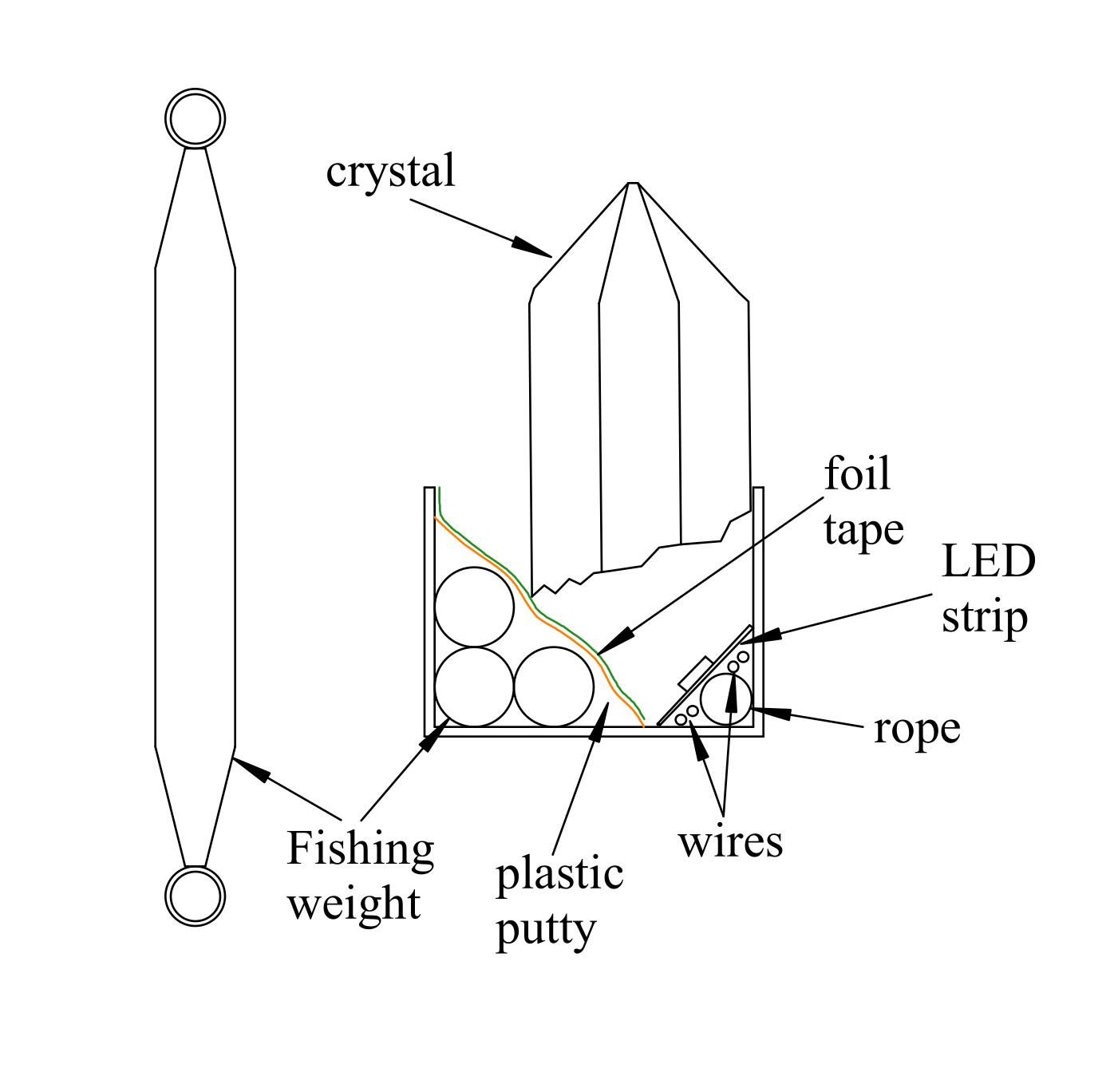
It was very likely that the chandelier would not hang straight. I put some big crystals in the bottom, also requiring a wider channel at the bottom, and this unbalanced it even more. The simplest way would be to have the same size crystals for the whole thing, and then it can be balanced with oblong fishing weights under the putty on the side needing the weight to balance it. (figure 7.5) I really liked the idea of the big crystals at the bottom. This required more weight than would fit inside the channel, so I cast a lead weight to attach to the channel outside of the channel but on the wall facing the center. This is optional, and smaller crystals all around or bigger crystals in the area needing more weight would allow the use of lead fishing weights inside of the channel. Lead is toxic to handle, so the weights should be handled using gloves.
I made the whole thing but did not glue the crystals in place on the side I knew would need the weight or put in the putty that would cover the weights. I hung the chandelier, and then with a small wire hook over the inner edge of the channel I attached a plastic bag to temporarily hold weight. Then I added weight to the bag and adjusted the location of it until I found the correct amount and location of the weight.
One method of making a counterbalancing weight would be to laminate strips of sheet lead, used for roofing and available at amazon.com or mcmaster.com. Cut it into strips with tin snips and glue the strips to make a weight the proper size and weight. If the strips are sanded a little to make them rough, epoxy will stick to it and hold the lead together. Some Bondo on the outside top and bottom could make it look like one solid piece. Again, use safety precautions when handling the lead.
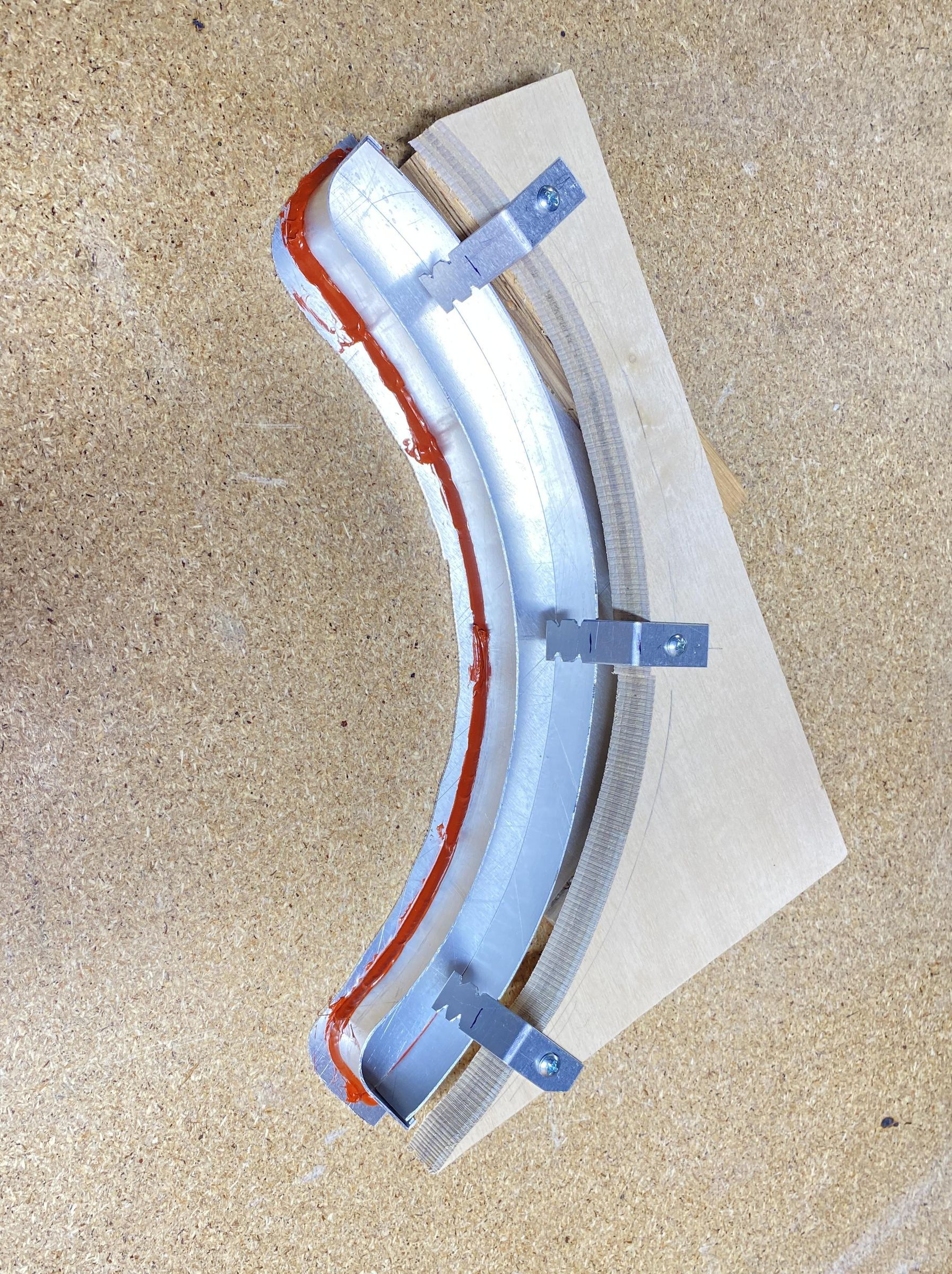
Since I had a more unbalanced chandelier, I ended up needing 5 pounds of lead. Fishing weights are an easy source of lead (Amazon.com). The whole thing weighs 25 pounds including the lead. I decided to cast a weight from lead. I made a sheet aluminum mold to cast the weight, the same height as the inner wall of the channel (plus some extra just in case), and 1” in width, and long enough to go between two of the supports. (figure 8) A mold made of plaster (carve the shape out of foam, cover it in plastic, sink that into some plaster) would work well too, but make sure the plaster is dry before you pour molten lead in it. I glued the sides of the form to an aluminum base with high temperature silicone sealant. Then it can be filled with water to see how much volume the lead will take. One ml of water equals 11.55 grams of lead. From this you can determine the amount of lead needed. A piece of wood temporarily holds some tabs of aluminum that will be embedded into the lead and can later be bent to hook over the inner edge of the channel.
I melted the lead in an old food can using a propane torch. Be sure to do this outside, stand upwind, wear safety glasses and gloves, and ideally wear a filter mask that handles lead fumes. I put the can over the propane torch. Pour a little melted lead into the bottom of the mold, and let it chill a little. If you put too much lead in at first, the aluminum will warp, the sealant will break, and the lead leaks out. If a little lead leaks out, that is ok, and once the bottom layer has solidified that will keep more lead from leaking out when you pour in the rest of it.
When it is all cast, the surface will have bubbles and grooves where adjoining layers meet each other. I filed down the edges, covered with a thin layer of Bondo, and then filed, sanded, and painted it to make it more presentable. Gloves, safety glasses, and a dust mask are needed for this. Lead is absorbed a little bit through your skin, but is especially a problem if you eat with lead on your hands. The aluminum tabs can be trimmed and bent over to hang the weight from the inside edge of the channel.
Electronics
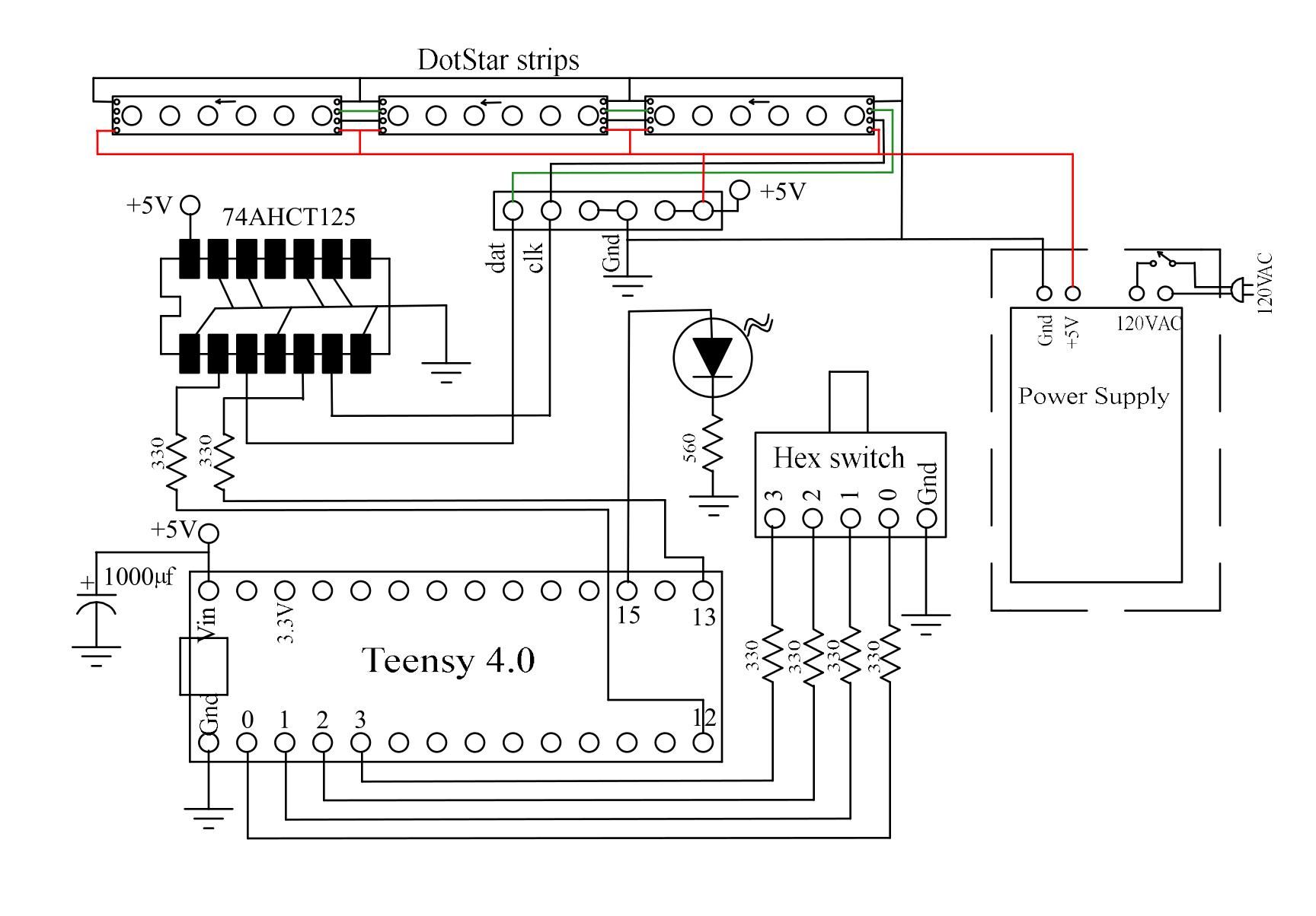
The Teensy microcontroller is programmed through the Arduino development environment. Instructions are at the www.pjrc.com website on how to add the Teensy ability to the Arduino environment. Be sure that you have the FastLED library installed, that is “included” at the beginning of the code.
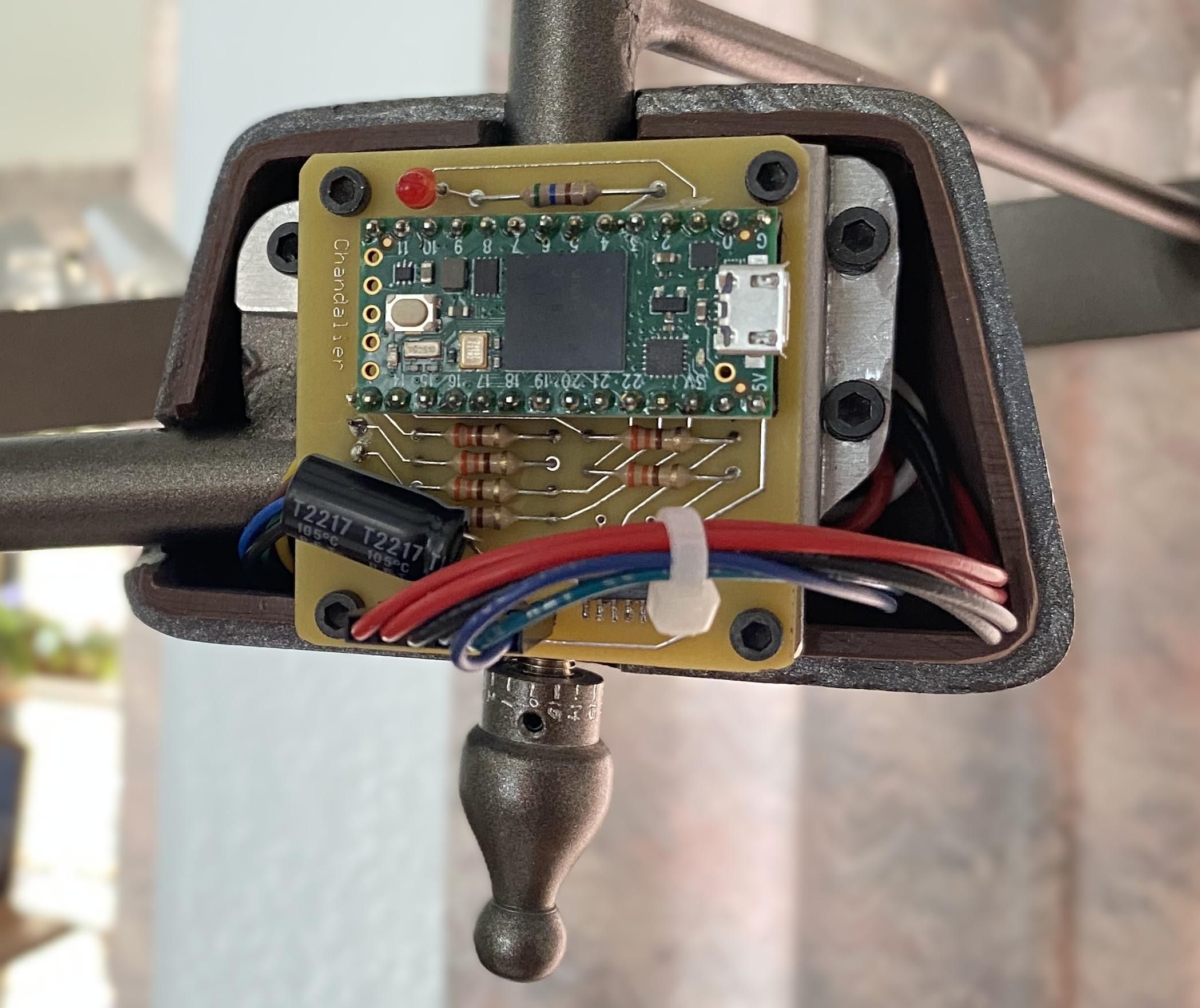
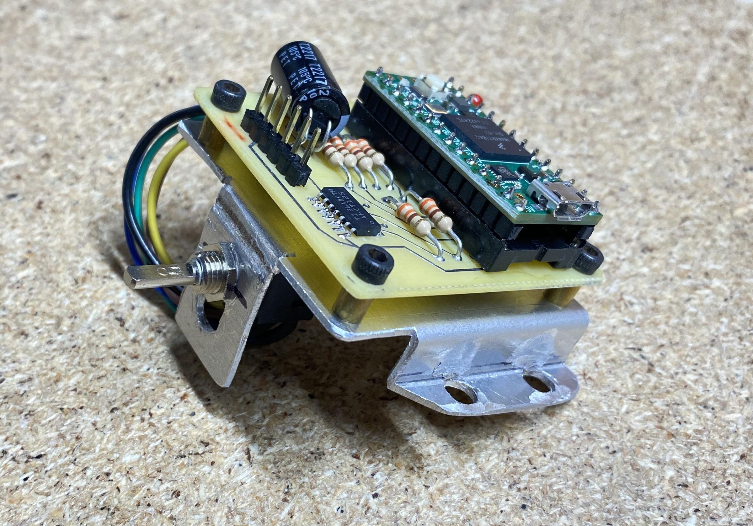
I designed a printed circuit board for this with ExpressPCB. You could wire it all by hand, but the buffer chip only comes in surface mount and the PCB makes it easier. If you want to wire it by hand, solder the buffer chip to a SMD-to-DIP adapter, and then mount that onto your circuit board. The buffer converts the 3.3-volt signal from the Teensy to 5 volts to drive the DotStar strips. The surface mount tabs are not too small to solder with a small tip on your soldering iron, some flux, and some skinny solder wire. An anti-static wrist strap and table pad are a great idea for soldering the static-sensitive parts of the circuit. I cut the header pins that come with the Teensy a little shorter before soldering them, giving a lower mounting profile. It is then plugged into the DIP socket. Figure 10 shows it in place at the bottom of the structure.
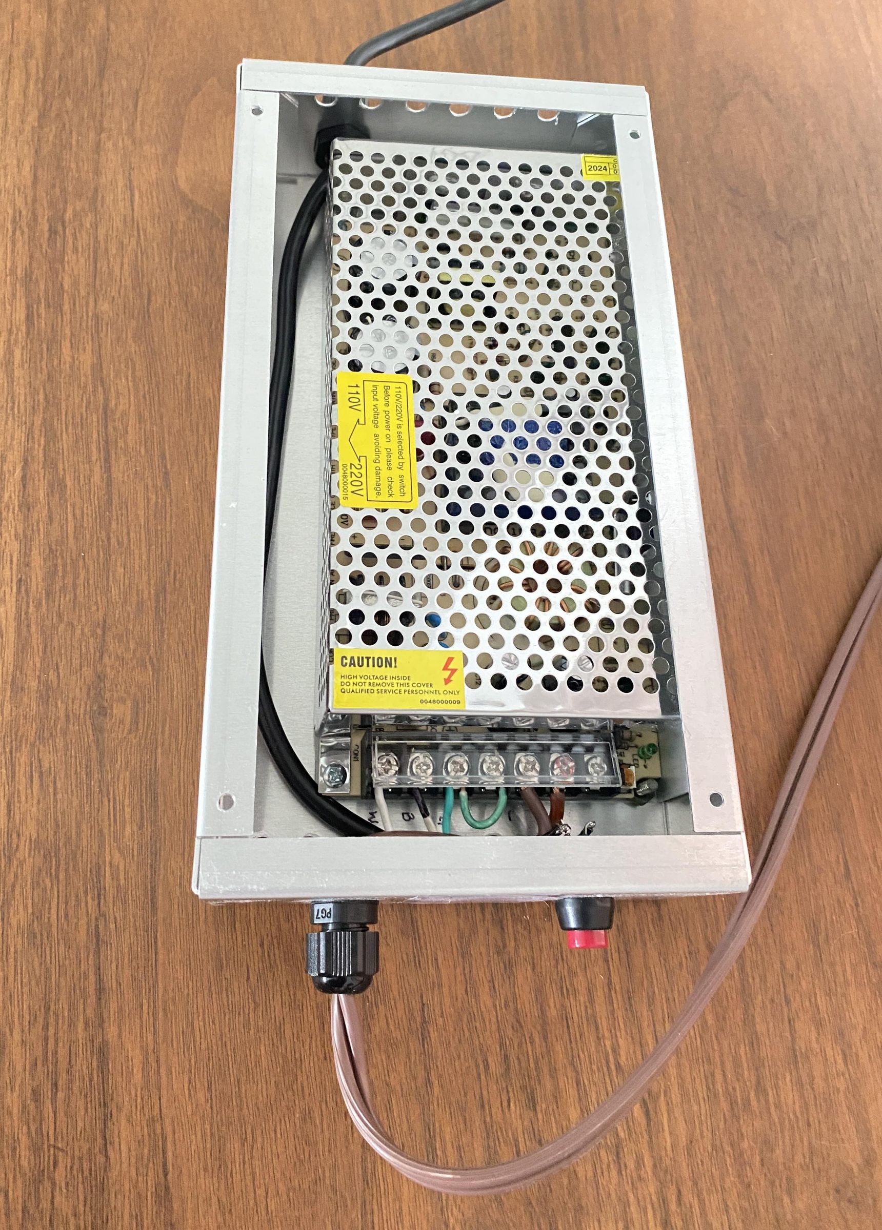
The ground of the power supply (Figure 11) is connected to the steel framing structure and to the aluminum power supply box. The red LED and its resistor are not necessary, but I put this onto all my microcontroller projects, which is useful when programming and getting it to work. If I can flash the LED, I know the basic program is working, and I can use flashes to tell me things while trying to debug the code.
I used a hex rotary switch mounted so that the shaft comes out of the bottom of the electronics package. The PCB is mounted to a piece of sheet aluminum that also holds the hex switch with its shaft pointing straight down and aligned vertically with the central shaft of the structure. (Figure 12) It allows selection between some different programs that I wrote, including one that switches between programs every minute.
The program called “Twinkles” causes crystals to flash all over the place with changing colors and each flash fading out before the next flash. To figure out the LEDs for each crystal, I made it light 20 LEDs in sequence at a time to observe and record the starting LED number and the number of LEDs for each crystal so that each crystal can have its own color.
NeoPixel LED strips would work, and cost a little less, but the DotStar strips are brighter and prettier. With the very fast PWM rate, they don’t flicker. An alternative is to use WS2812B strips, that are equivalent to NeoPixels, can be purchased online, and imported from China are much less expensive.
Conclusion
This project offers a delightful blend of challenge and creativity. Each step, from forming metals to programming LEDs, is a journey into the fascinating world of making. As the vibrant hues of the DotStar LEDs illuminate the crystals, there's a profound sense of accomplishment that photos and videos simply can't capture. The beauty of nature, accentuated by the brilliance of technology, creates an enchanting spectacle that is sure to captivate anyone who sees it. This project is as rewarding as it is illuminating.
About the Author
Victor Chaney has been an amateur maker all his life, and has written for Make Magazine, Nuts and Volts magazine, and Instructables. His website has more of his unusual creations. He is a dentist by profession and has a degree in Physics as part of his background, as well as learning from books and The Web.
Links
www.chaneyproductions.com is Vic’s website.
chaneyproductions is Vic’s YouTube channel.
www.pjrc.com has everything you need to know about the Teensy 4.0 microcontroller.
www.adafruit.com has tons of information about the DotStar LEDs.
www.expresspcb.com has what you need to order the printed circuit board.
www.mcmaster.com has more hardware and materials than anywhere else.