A Raspberry Pi NAS That Really Look Like a NAS
by tobychui in Circuits > Raspberry Pi
191003 Views, 850 Favorites, 0 Comments
A Raspberry Pi NAS That Really Look Like a NAS


Why a Raspberry Pi NAS
Well, I have been searching for a beautiful yet space saving Raspberry Pi NAS from the internet and I found nothing. I did find some NAS design with a Raspberry Pi get glued to a wooden based but that is not what I want. I want a real NAS. Those looks like professional and durable that can be used to store my massive amount of movie collections. So I decided to build myself a NAS from the ground up. Yes, you heard that. FROM THE GROUND UP.
In this project, I will not use any existing parts that is specially design for Raspberry Pi NAS. Instead, I will be using some common parts you can easily found on Amazon or ebay. So, lets get started!
By the way, that is my initial design sketch up there.
3D Modeling and Printing


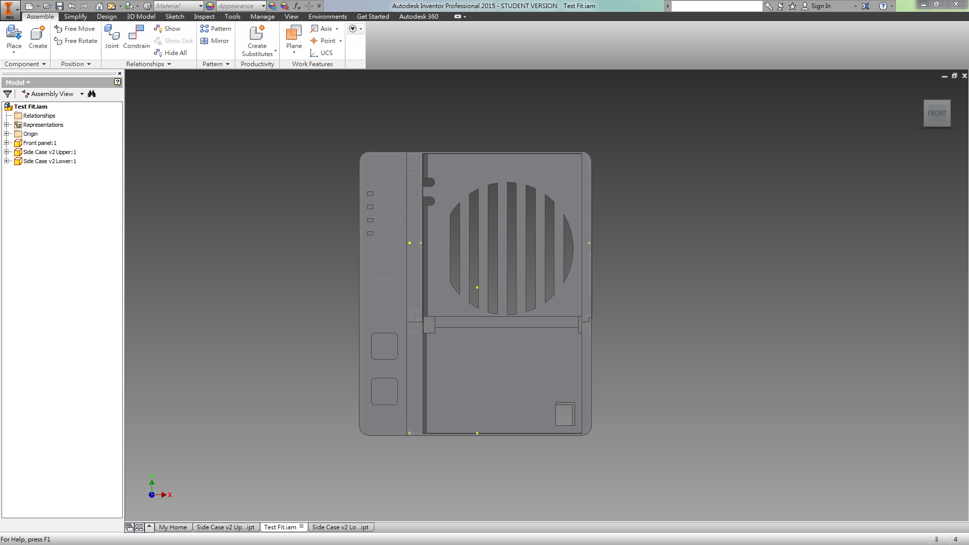
After I have designed my NAS case in Autodesk Inventor, I test fit them to see if every joint is correctly designed.
Let me explains how the parts works. This case is divided into three parts. The left section is for the power management board and Raspberry Pi 3B+. You can use a Pi 3/ 2B+ as well as their footprint is the same. But you would want to use the Pi3B+ as it is faster. I will explain the detail later.
The right section of the case is design to hold two 5inch hard disk how swap mount (See picture 4). And the extra space at the back is for a 7 cm fan, a DC jack and the cabling.
3D Models Download (Case)
The 3D models can be downloaded here. License under:
Attribution-ShareAlike
CC BY-SA
Printing and Assembling


After the prints has finished, we can start building the case.
The case is made up of three parts as mentioned before, you can attach them together with some M3x5 screws and M3x10 (for the top and bottom screw holes). Afterward, inserting the button caps into the holes and you will be ready for the electronic parts.
Buttons and Signal LEDs


Actually the buttons and LEDs are some simple circuit that attach the signal from the Pi's GPIO to the front panel. There is nothing much special here except the button is a bit tricky. I would recommend you to do some test print before fitting the PCB inside the case with glues. That can make sure the quality of the buttons are good and clickable. In my design, as the RED LED require 5V, so I added a resistor on it and planned to directly connect the LED VCC pin to the power management board's 5V output. You can use the Raspberry Pi's 3.3V GPIO pin as well without the need for the extra resistor.
Test Fitting


After receiving the hot plug bay from ebay, I placed two 2mm acrylic plate on the bottom and top of the right case. This is used to strengthen the support for the two HDD bay as HDD are kind of heavy after inserting into the bay.
Afterward, I used an old USB hard disk drive which, usually contain some kind of SATA to USB converter circuit board. For the one I bought, it come with a pre-soildered 12V input port that can support 12V power input for a 3.5 inch HDD. I attached them to the end of the two HDD hot plug bay and attached two cable to the end of it. One of the cable is a 2.1mm DC jack for the 12V input and the other one is a micro USB male cable for data and 5V. Both of them are special ordered so they bend in a direction towards the bottom and preserve space.
The finished product should look something like the picture 5.
Tape and Glue


Now, we need to tape and glue the HDD hot plug bay into the case. First, I would recommend sticking a double sided tape on the metal bracket of the bay. After the bay is inserted and secured, put some superglue on the contact between the Acrylic plate and the metal bracket. But REMEMBER TO REMOVE THE PAPER ON THE ACRYLIC PLATE. I have forgotten to do so for the first time and I have a bad time moving everything out and do the same process again.
After finishing this process, you would not see two slot stick out of the right case and you can open then and close them via the handle build onto the hot plug bay.
Test Fit


Now, stick your hard disk into the bay, and it should fit perfectly. (If not, you should ask for a refund from your seller of the hot plug bay xD)
You might notice that there are two rounded slot at the top back section of the right case. Those are for the USB cables. You can now stick the cables out and make it looks more tidy before start working on the electronics.
Power Management Board


Here comes the power management board.
In the middle is a Tinduino. It is a self developed Arduino for low cost deploy and development from our Lab. Of course you can use an Arduino UNO for this and control the relay on off when there is a button press.
There are plenty of tutorials online which teach you how to make a board like this, for example:
https://www.instructables.com/id/Toggle-Switch-Wit...
It is basically a latch switch so you can do it in whatever style you want.
On the right is a buck converter. It steps down the voltage from 12V to 5V for the Pi and the Arduino.
And lastly, the bottom 3 port, from left to right is 12V power in, 12V power out for HDD1, 12V power out for HDD2
Fixing Everything Together

Now, attach the power management board with the raspberry pi as shown in the picture above.
Plugin the 12V power input and everything should lights up (If not, maybe you can short the button and activate the Arduino Relay Toggle System)
Close the Case and You Are Done!


Now, screw in all the screws, plug in the power cable and you are ready to go?
Not yet. We still need the software. But here is what the finishing hardware looks like.
As the software is still in development, I would recommend installing some open source OS / NAS system like the FreeNAS or open media vault. But I won't do that as I have planned to build my NAS from the ground up.
So what would I do next? Write my own NAS operating system!
Install OS and Start Creating Your Own NAS Interface

Install the Raspbian Lite from the Raspberry pi website.
https://www.raspberrypi.org/downloads/raspbian/
and install it on your SD card. I think there are plenty of tutorial online so I don't duplicate those parts in this instructable.
Move On? ArOZ Online System!


You might remember my post two years ago which is a Raspberry Pi media center system called
ArOZ Online (Alpha)
https://www.instructables.com/id/Simplest-Media-Ce...
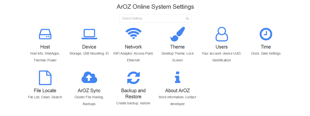
Now, I have completely rewritten it into a brand new, DSM like Web UI called the ArOZ Online (Beta)
This system will works on both Window Host and Linux Host (of course Rasbian as well).
Comming Soon!

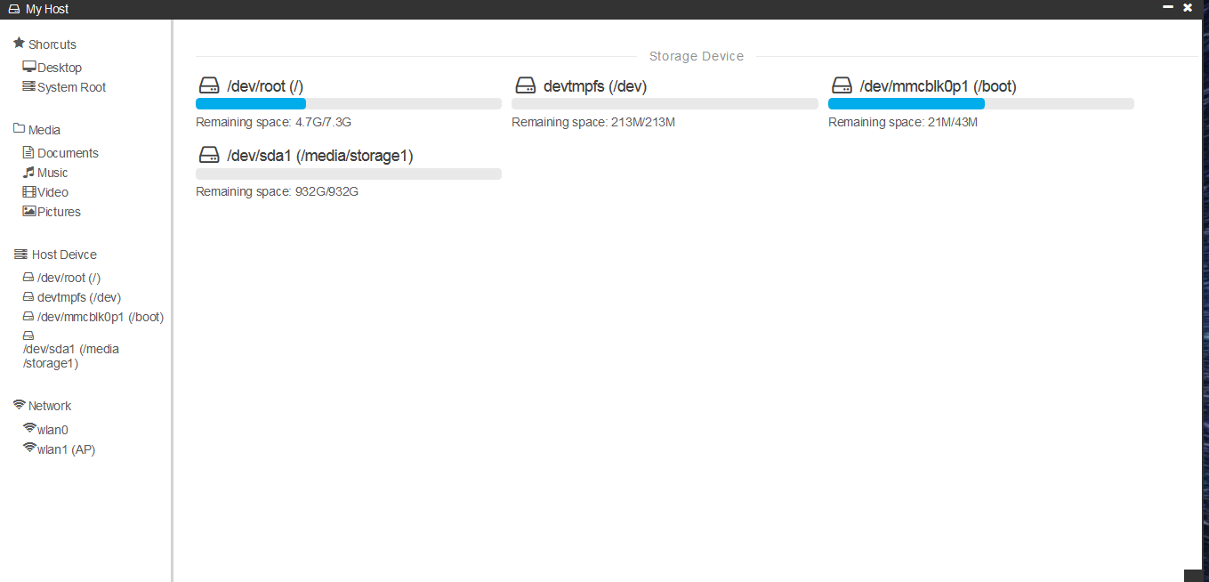
Well, at least for now the system I wrote detects the 1TB drive I have inserted into the NAS.
So what next? The software still needs years of developments in order for it to run smoothly.
Currently, the max speed of transfer over 5G WiFi to HDD is around 100Mbps. Which is kind of OK for the fact that it is just a tiny little computer that is handing all your request. And it can reach around 93Mbps while transferring with Samba (Window SMB / Network Disk). This might be the advantage of using the Pi 3B+.
Please look forward to the update instructable to this project next year :))
======= April 2020 Updates ========
You can now get a copy of the semi-finished, custom written NAS OS with web desktop over here :)