ALorAtMe - a LoRa Alert Me Circuit
by mars91 in Circuits > Wireless
84 Views, 0 Favorites, 0 Comments
ALorAtMe - a LoRa Alert Me Circuit
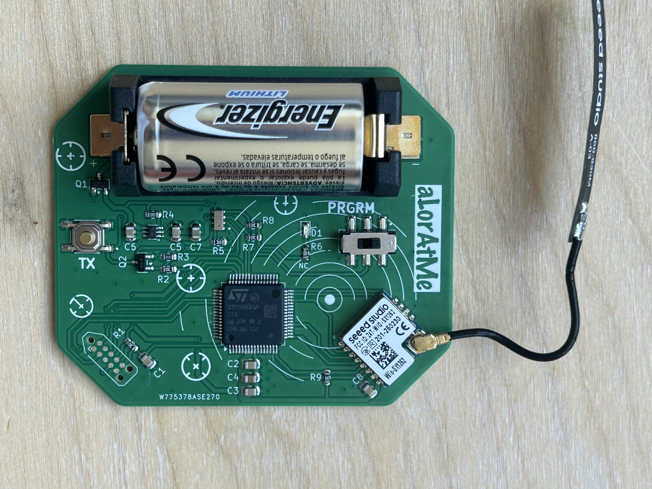
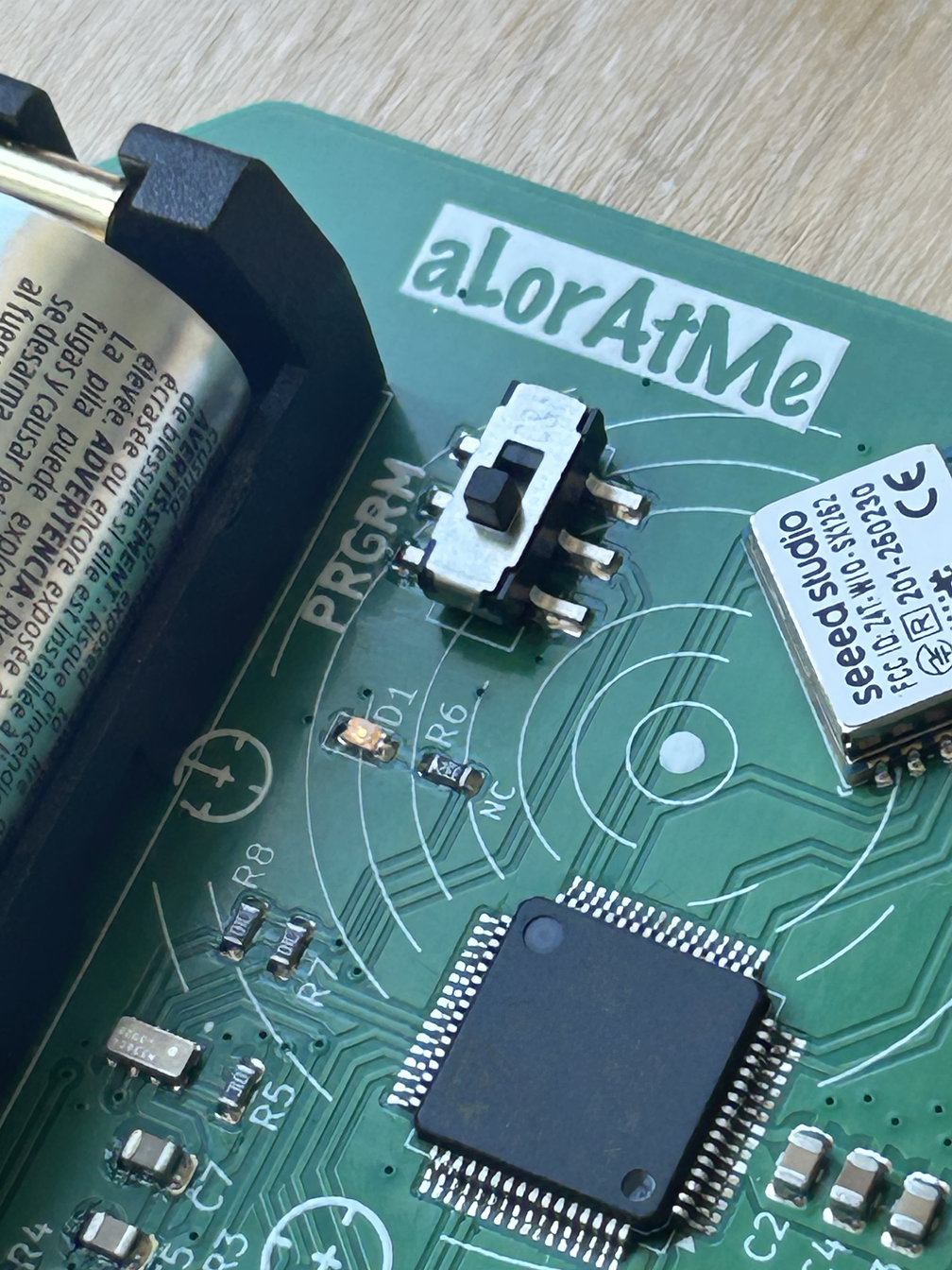
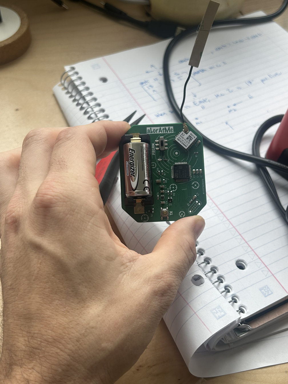
A battery-operated, extremely low-power alarm that sends a LoRa radio transmission.
Why?
I built this mostly for fun while experimenting with ultra-low-power, alarm-based circuits. When an alarm wakes up power-hungry components only when needed, then shut them off completely.
The less practical inspiration came from arriving home to find every deadbolt and chain locked. A receiver inside the house could detect the ALorAtMe radio in my car and turn on an LED, giving my girlfriend a heads-up that I’m almost home (radio waves travel far). Whether I’ll actually build that part is another question :)
Supplies


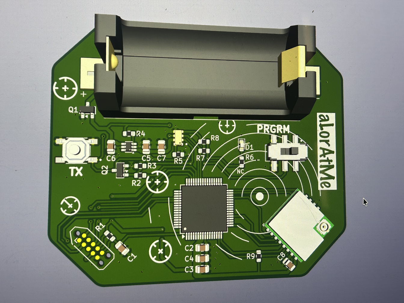

BOM
Main Components
- STM32G0B1RETx microcontroller
- Seeed Studio Wio-SX1262 LoRa module **I use the 915MHz Module, legal where I live**
- RV-3028-C7 real-time clock
- SiP32432DR3 power switch
- CR123A battery holder
Transistors
Resistors
- 6× 10 kΩ resistors | Package: 0603 | References: R1, R2, R5, R7, R8, R9
- 2.2 kΩ resistor | Package: 0603 | Reference: R6
- 1MΩ resistor | Package: 0603 | Reference: R3
- 100 kΩ resistor | Package: 0603 | Reference: R4
Capacitors
- 5× 0.1 µF capacitors | Package: 0805 | References: C1, C2, C3, C5, C8
- 2× 1 µF capacitors | Package: 0805 | References: C6, C7
- 4.7 µF capacitor | Package: 0805 | Reference: C4
Controls and Indicators
- LED | Package: 0603
- push button
- six-position switch
Programming software
- STM32CubeMX
- STM32CubeIDE
Programmer Tools
more on programming below
- STLINK-V3MINIE
- Tag-Connect TC2050-IDC-NL-050-ALL | Normal orientation.
- TC2050-CLIP-3PACK retaining clip set
- custom 14-pin-to-10-pin adapter PCB
- 100 Ω 0603 resistor.
- Samtec FTSH-105-01-F-DV-K-TR
- Samtec FTSH-107-01-L-DV-K-P-TR
The complete programming connection is:
Computer -> STLINK-V3MINIE -> custom 14-pin-to-10-pin adapter PCB -> Tag-Connect TC2050 cable -> alorAtMe PCB
PCB Ordering
Soldering
- 110V 850W Soldering Hot Plate (this one is big - i'm sure a small one would work)
- Solder Paste
- Solder Flux
- Stencil Squeegee
Programming the STM32
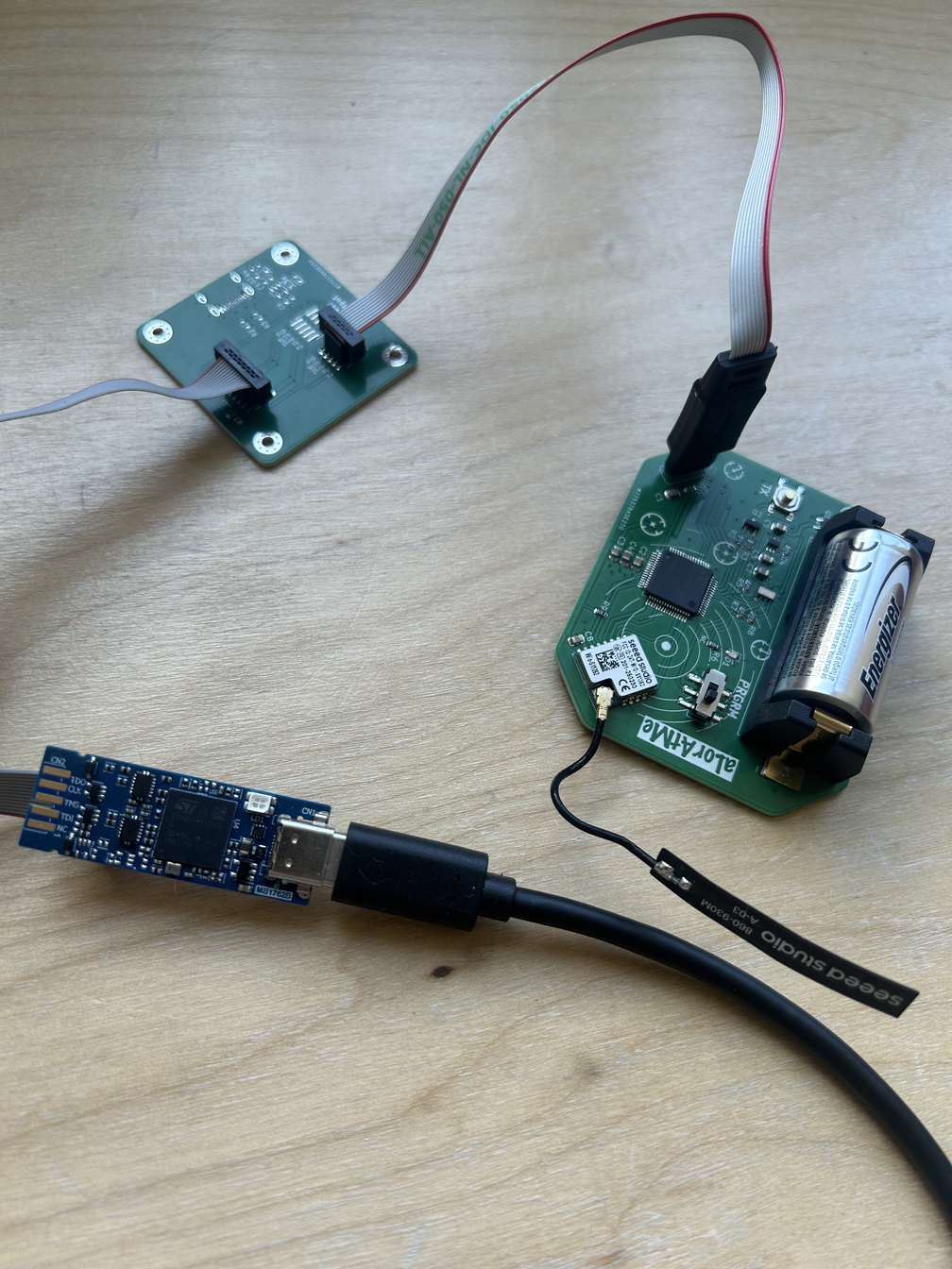
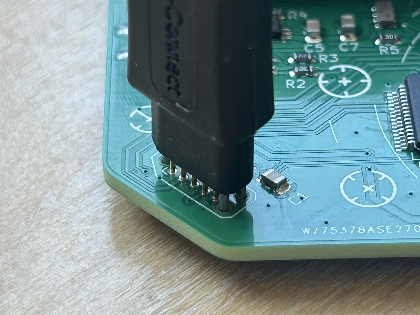
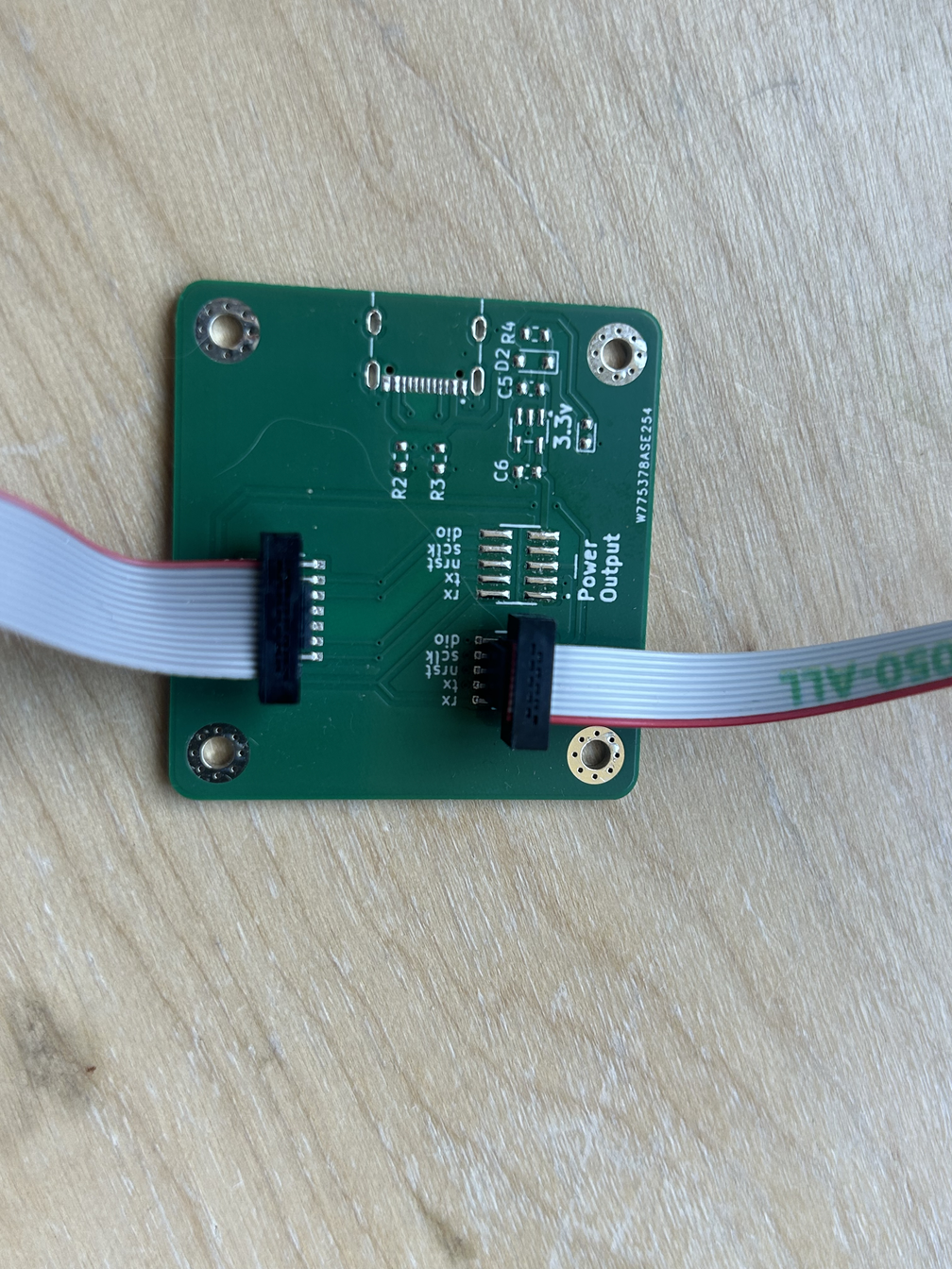


Intro
The problem is simple: the STM32 has blank pins waiting for connections so code can be uploaded.
My programming solution includes using some custom hardware. I really like the connectors from Tag-Connect, and I use the STLINK-V3MINI to program my STM32 boards.
The STLINK-V3MINI is a 14-pin connector, but I only need 7 signals. IMHO it's too big. So I end up using the 10-pin Tag-Connect programmer, which has the minimum number of pins I need (10 is more than 7 but less than 14). If Tag-Connect made an eight-pin version, I probably would have bought that.
**I only have this contraption because I built some boards a while ago with a very small programming footprint- too small for the full 14-pin header.**
Programming Pins
- GND
- V-SENSE
- SWDIO
- SWCLK
- NRST
- UART RX
- UART TX
GND and V-SENSE are used for the power reference. SWDIO, SWCLK, and NRST are used for uploading code and debugging. UART RX and UART TX are used for serial-print debugging.
The STLINK-V3MINI includes extra pins for more advanced debugging features, but those features are not really needed for this circuit.
The Adapter PCB
I have several simple custom PCBs whose entire purpose is to route the 14-pin connector to a 10-pin connector. The complete connection looks like this:
Computer -> STLINK-V3MINI -> custom PCB with 14-pin connector -> custom PCB with 10-pin male connector -> Tag-Connect TC2050 cable -> my circuit board
You may notice that the PCB adapter in my pictures looks a little different from the PCB files I provided. The version shown in the pictures was an earlier design with several parts I never installed because of an error. The PCB files and schematics I provided show the version you actually need.
The TC2050 tag connect also has retaining clips called the TC2050-CLIP-3PACK Retaining Clip. They hold the cable firmly against the PCB while programming it.
Fin
Quite a journey just to get code onto a circuit board...
The nice thing about this Tag-Connect custom solution is that it is a quality product and, hopefully, something you only need to order once. After the setup is complete, you can program and debug STM32 boards while using a very small programming footprint for each PCB.
Between the STLINK-V3MINI, the custom PCB, and the Tag-Connect cable, I expect the complete programming setup to cost about $100 USD. Hopefully, a one-time purchase that gives you a small, high-quality programming and debugging connection for future boards.
You could also use the TC2070-IDC-NL-050 with the GRIP-14 3-Pack. That option would let you skip the custom adapter PCB. The TC2070 also uses compact pads, and KiCad includes its footprint.
How the Ultra-Low-Power Alarm Works
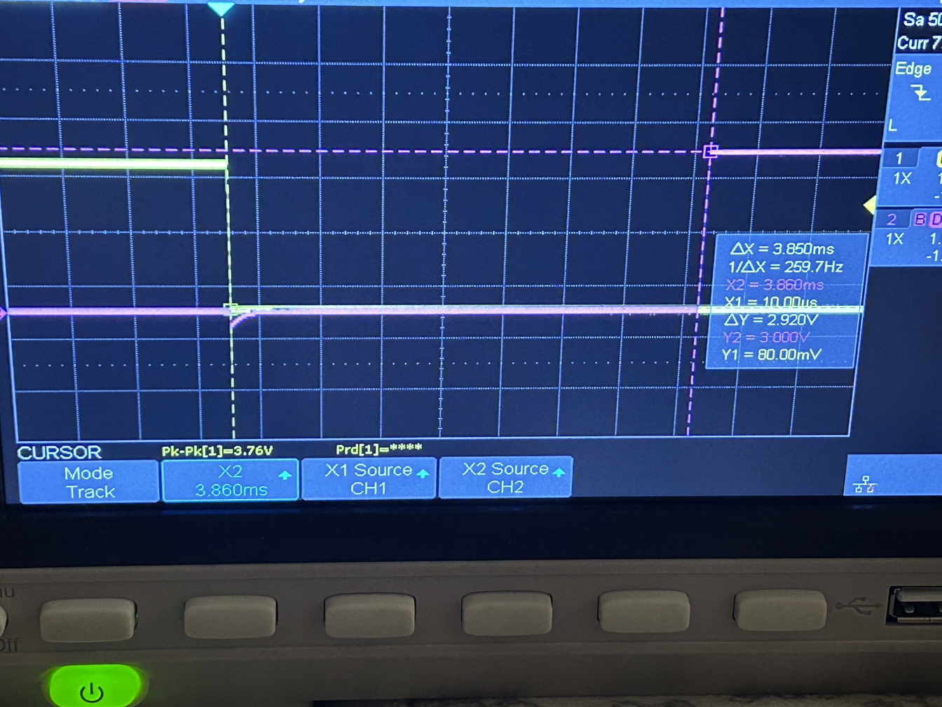
The circuit comes down to two great parts working together: the SiP32432DR3 and the RV-3028-C7. The RV-3028-C7 is a high quality real-time clock, or RTC, that uses nanoamps to control an alarm. That's a few 1/1000000000 of an amp! The SiP32432DR3 is a power switch that lets power pass thru when it is told to turn on. It also uses only nanoamps.
Together, these two parts create an alarm and power system that uses almost no current.
The RV-3028-C7 Code
The RV-3028-C7 can do much more than just wake up a circuit. I had a lot of fun writing the C code for this part.
The code provided at the bottom is written from scratch using the RV-3028-C7 datasheet. In the code, you can see the comments I added while I figured out how to write firmware. With AI this code could probably be written in minutes instead of the 3+ days it took me. However, now when I look at the RTC, I feel like we are friends. We understand each other. If AI had written the whole thing, I might look at the RTC like a black box that I just hope is working correctly.
The RTC has three main alarm modes:
- A calendar alarm
- A countdown alarm that activates every N seconds
- A periodic alarm that activates every second or every minute
The code I wrote currently supports only the second every-N-seconds countdown alarm.
The RTC Interrupt Line
When the countdown alarm activates, the RTC pulls an electrical line low.
On my PCB, this line is called RTC_INT. It is pulled up to the battery voltage, which is about 3 volts, thru a 100 kΩ resistor. The line normally stays high. Almost no current flows thru while idle since the RTC_INT line has no path to ground or 0 volts. Every N seconds, the RTC briefly pulls the RTC_INT line down to 0 volts. The signal basically switches between a 1 and a 0.
Convenient that the SiP32432DR3 turns on when it receives a low signal, a 0. It has a pin labeled ON (tied to RTC_INT). When this pin is high, the SiP32432DR3 blocks power. When the ON pin is pulled low, it allows battery power to pass thru to the rest of the circuit.
Turning On the STM32
When the RTC alarm pulls the line low, the SiP32432DR3 sends power to the STM32. Once the STM32 starts running, it pulls the ON/RTC_INT line low thru its own latch signal. This keeps the power switch turned on even after the RTC stops pulling the line low. Essentially, the STM32 keeps itself alive. Sorta like now after we are born, we have to drink water every day to stay alive.
When the STM32 finishes its work, it releases the latch pin; the ON/RTC_INT line returns high; the power switch turns off; and the STM32 loses power.
You may notice that there is an NOSFET(BSS138) between the STM32 latch pin and the latching system. The ON/RTC_INT line stays high at about 3 volts for 99.9% of the time. It is not good to continuously apply a high voltage to a microcontroller pin when the microcontroller is powered off trying to sleep. The NOSFET isolates the STM32 pin while the board is off.
Race Condition ?
There are real warning flags about a possible race condition...
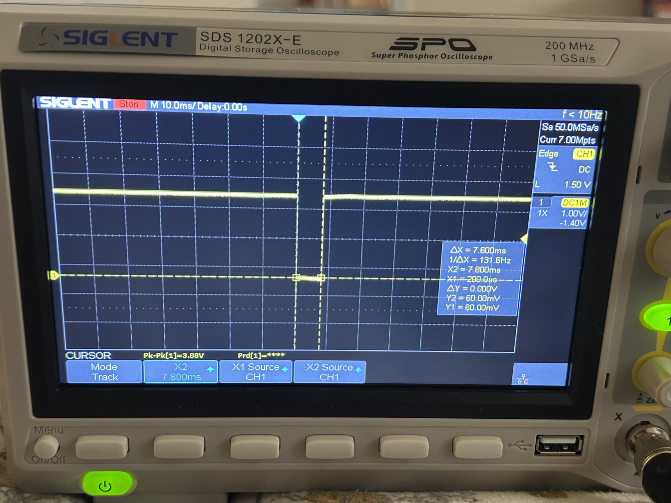
The circuit has power only while the ON/RTC_INT line is low. In my code, I programmed the RTC to pull the line low for 7.8 millisecond pulse. Of the available pulse options for the every-N-seconds countdown alarm, 7.8 milliseconds is the longest pulse. Wish the RTC would pull the line low and leave it low until the STM32 cleared it, but that is not how this alarm mode works. ̄\_(ツ)_/ ̄
This means the STM32 has about 7.8 milliseconds of guaranteed power to start up and latch the power switch on.
How long does the STM32 actually take to latch?
I measured it with an oscilloscope. In the pink trace above, I measured the time between the interrupt line being pulled low and the STM32 activating its latch signal. The result was about 3.8 milliseconds!!!
Nice this non optimized (in software) STM32 can start running and perform an action in such a short amount of time. However, 3.8 milliseconds still felt a little close to the 7.8-millisecond alarm pulse.
Extra Power-On Time
But I also measured the output of the SiP32432DR3 without allowing the STM32 to latch the circuit.
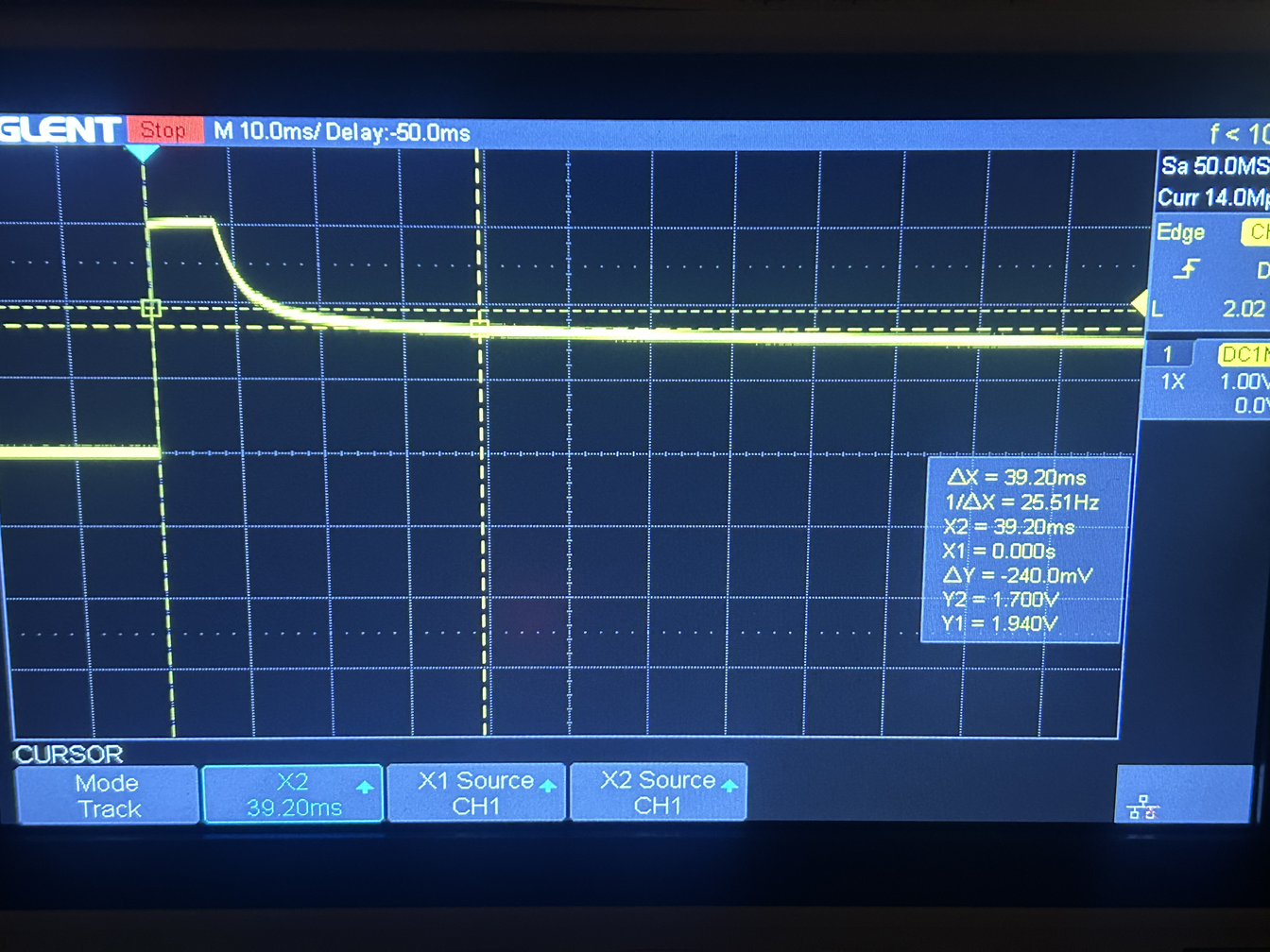
That test was a big relief. In the yellow trace of the second plot, the power output stays strong for exactly the 7.8 millisecond plateau. After that, the voltage falls very slowly instead of shutting off instantly.
It takes roughly 40 to 60 milliseconds for the voltage to fall to about 1.7 volts, which is around the point where the STM32 stops operating. This extra time comes from the capacitance on the power line. It depends on several analog factors, including:
- Filter capacitors
- PCB layout
- Temperature
Because of this, I would not treat the 40-to-60-millisecond window as a perfectly guaranteed value. Still, since the STM32 latches the circuit in about 3.8 milliseconds, I'm confident that there is plenty of time. This is a robust alarm latch circuit.
Other Alarm Modes
The RTC’s calendar alarm does hold the interrupt line low until it is cleared. My code does not currently support the calendar alarm or the periodic every-second or every-minute alarm modes. Still my code should hopefully be a useful starting point for anyone (or any AI) that wants to add those features.
Storing the Time
The RTC also stores the current UTC time. My code stores it as a `uint32_t`, so it should remain valid until the year 2106 :)
Setting the UTC time is a little awkward. You set it in the code using:
Now the RTC keeps track of the time by itself using nano amps. But, if that line runs again every time the STM32 starts, the clock will reset to the same original time... Because of that, I flash the board twice. The first time, I flash it with "RTC_SetUnixTime()". Then the second time I comment out this line and flash again.
There is also some code in main.c that sets up the periodic countdown timer and the setting(s) that tells the RTC to use its backup battery. This also needs to be configured only once. These settings are stored in the RTC’s nonvolatile EEPROM memory. As long as the backup battery remains connected, the RTC remembers the time and knows what it is supposed to do.
Power While Programmed
The STM32 needs power while it is being programmed. Flipping the PRGM switch on the PCB keeps the entire circuit powered on, allowing the STM32 to be programmed and debugged without the alarm circuit shutting it down. The TX push button also pulls the RTC_INT line low so in my circuit, pressing the TX button causes the STM32 to wake up and send a LoRa radio message.
LoRa Radio



For the LoRa radio, I wanted to use a modern, powerful, and fairly inexpensive chip. I chose the Seed Studio Wio-SX1262, which uses the SX1262 sub-GHz radio made by Semtech.
SX1262 Code
This was the part of the project I was most nervous about. I am comfortable writing C code for I2C devices or simple commands with easy levels of abstraction. However, I had never written firmware for a specific, complicated radio device before.
This ended up being a nice learning experience. Luckily, the people behind the SX1262 provide an official driver library on GitHub:
https://github.com/Lora-net/sx126x_driver
I copied these files from the repository:
- sx126x_regs.h/.c
- sx126x_status.h/.c
- sx126x.h/.c
- sx126x_hal.h/.c
I then created my own STM32-specific files:
- sx126x_hal_stm32.h/.c
HAL - The Hardware Abstraction Layer
The part that made this project much easier (and, in my case, probably do able) was the hardware abstraction layer. For example, inside sx126x.c, you can find functions like this:
Notice that this function calls sx126x_hal_write(). HAL stands for Hardware Abstraction Layer. Basically, the driver is saying, “I will handle the radio commands, but you need to tell me how to communicate with the hardware.”
Most of the radio functions depend on only a few basic HAL functions, such as sx126x_hal_write()
My job is to connect those functions to my STM32 hardware. Which is much easier.
You can see my version inside sx126x_hal_stm32.c:
The arguments and return values match what the SX1262 driver expects. Inside the function, I added the STM32 code needed to send the command and data over SPI. This provided level of abstraction was honestly a huge relief. I did not have to rewrite every radio command from scratch. I only had to create the connection between the Semtech driver and the STM32.
My abstraction code is also covered in comments I wrote while learning, so take a look at sx126x_hal_stm32.c for more explanation.
My LoRa Code
The abstraction layer made it possible for me to write firmware for the LoRa radio, but that does not mean there was no work left. I still spent several days working on my own lora.h/.c files.
The SX126x driver is a strong and useful library, but it is still up to you to:
- Configure the interrupts
- Build the correct "sx126x_stm32_context_t"
- Handle the correct "sx126x_status_t" return values
- Select the radio frequency
- Configure the modulation settings
- Set up transmit and receive modes
- Choose from the many other available radio settings
I use **915 MHz**, which is commonly used for LoRa devices in North America. Once again, the lora.h/.c files contain many of my comments. Took several days and a lot of work to write, but was very satisfying. Just like with the RTC, I now feel like the radio and I are friends.
My lora.h/.c code mainly initializes the radio and sets it up for either transmitting or receiving. It is not a huge, fully optimized radio library. It simply does a good job of setting up the radio for this project.
Frequency and Antenna Warning
If you plan to build this project in Europe or another part of the world, check your local radio-frequency laws. Different countries allow different frequency bands and power levels.
You will also need to:
- Use an antenna matched to your chosen frequency
- Order the right Seed Studio Wio-SX1262
- Change the radio-frequency settings in the code
- Make sure your transmit power and timing follow local laws
Do not assume that the 915 MHz settings used in my project are legal everywhere.
Hardware Connections
The hardware connections are fairly simple. The radio mainly uses:
- SPI
- An interrupt line
- Reset and busy signals
- Power and ground
- A few other control wires
If you need a refresher on using SPI with an STM32, DigiKey has a great video
STM32CubeIDE and STM32CubeMX


STM32CubeIDE & STM32CubeMX
These tools are part of what makes STM32 so great. STM32CubeMX is used to select the chip and assign pins. STM32CubeIDE is where you write, build, debug, and upload the C code. Depending on which STM32 software version you install, CubeMX may be built into STM32CubeIDE, or you may need to run/download it as a separate application.
Creating the Project
Open STM32CubeMX and create a new project using the STM32G0B1RETx chip.
Once the project opens:
- Go to Project Manager.
- Enter a project name.
- Select STM32CubeIDE as the toolchain.
- Click Generate Code.
CubeMX should now create the basic folders and files needed to get started. The Inc folder should contain header provided files such as:
- main.h
- rtc.h
- lora.h
- The SX126x driver header files
The Src folder should contain source files such as:
- main.c
- rtc.c
- lora.c
- The SX126x driver .c files
Opening the Project in STM32CubeIDE
Open STM32CubeIDE and go to:
File -> Open Projects from File System
Select the project folder created by CubeMX, then import it. If your STLINK-V3MINI is connected correctly and the board is powered, you should now be able to build the project and upload the code. Remember that my board must be kept powered while programming. Flipping the PRGM switch keeps the circuit turned on so the STM32 does not shut itself off in the middle of programming or debugging.
Using UART for Debugging
UART printing is extremely useful. It lets the STM32 send text messages back to your computer. You can use these messages to check whether the RTC initialized, whether the radio started correctly, or where the program stopped.
My UART is configured for:
- 115200 baud
- 8 data bits
- No parity
- 1 stop bit
On my Mac, I usually find the serial port by opening Terminal and running:
You may see a port name similar to "/dev/tty.usbmodem103"
You can then connect to it using:
Main Pin Setup
The main peripherals used by this project are:
I2C for the RV-3028-C7 RTC; SPI for the SX1262 LoRa radio; UART for serial debugging; GPIO pins for radio control and power latching; An external interrupt for the LoRa radio. I use the STM32’s internal clock, so the board does not require a separate external clock crystal
GPIO Pins
The five extra GPIO signals are:
- LORA_NSS_Pin Output, push-pull
- LORA_RST_Pin Output, push-pull
- LORA_BUSY_Pin Input LORA_BUSY_GPIO_Port
- LORA_DIO1_Pin Rising-edge EXTI input
- MCU_LATCH_Pin Output, push-pull
The DIO1 interrupt is especially important. The SX1262 uses DIO1 to alert the STM32 that something has happened, such as a radio tx or rx. In CubeMX, LORA_DIO1_Pin should be configured as an external interrupt input triggered on the rising edge. The matching interrupt should also be enabled in the NVIC settings.
SPI Setup
The SX1262 communicates with the STM32 using SPI. For this project, the STM32 acts as the SPI master. The radio acts as the SPI device being controlled.
Important SPI settings include:
- Master mode
- Two-line communication
- 8-bit data
- Most-significant bit first
- Software-controlled NSS
The LORA_NSS_Pin is controlled manually in the code instead of letting the SPI peripheral control it automatically.
Possible Improvements
If I redesigned this board, I would break out the I2C pins to a small connector or set of pads. That would make it easy to connect a I2C sensors. An ultra-low-power LoRa device that wakes up, reads a sensor, sends the data, and shuts itself off sounds pretty useful.
I would also connect an ADC GPIO pin to the battery through a resistor divider. The STM32 could measure the battery voltage and include it in the LoRa message. The reading would provide a good estimate of the battery’s life and warn you when it is getting low.
Assembly

Tips
Align the stencil over your board. Spread solder paste over the holes and use a squeegee to push the paste through. Make sure the stencil is flush against the board and everything is nice and clean.
Next, carefully place all the components in their correct spots.
Reflowing with a Hot Plate
Here’s my process:
- I place the board, with all components and solder paste, on the hot plate while it's off.
- Then I turn it on and wait for the temperature to reach 215°C.
- Around 200°C, you'll see the solder start to melt.
- Once it hits 215°C, turn the hot plate off.
- Carefully move the board (I use needle-nose pliers) onto a cooling surface (like a cookie sheet).
Post-Reflow Cleanup
Check for solder bridges, unintended blobs connecting pads. If you spot any:
- Dab some flux on the bridge.
- Use a hot soldering iron and gently drag across the area.
- Clean off the flux using isopropyl alcohol and a Q-tip. Burnt flux is sticky and turns yellow-brown.
Also, keep your soldering iron tip clean by wiping it with some solder and a damp sponge.
Customize Your Board/Software

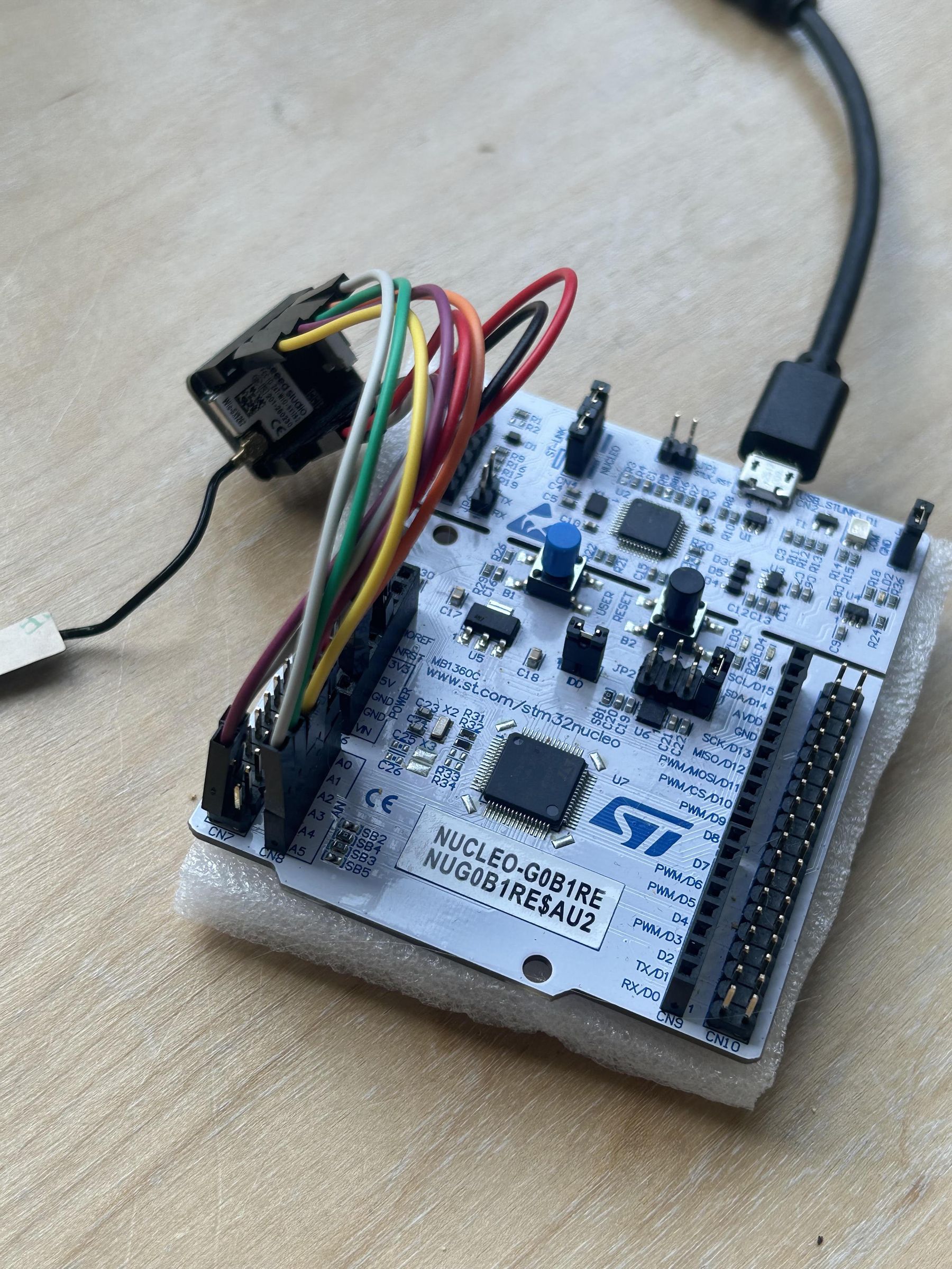
You can customize the alarm rate and the data sent in each LoRa packet. I set my alarm to trigger every 120 seconds.
My packet includes the name stored in MY_SECRET_CODE and the RTC’s Unix timestamp. On the receiver side (still in the nucleo and jumper wire phase), you could ignore unwanted messages by checking whether each packet begins with the correct MY_SECRET_CODE.
And that is it. Thanks for checking out my project!
STL File
A case for it