APOCALYPSE COMPANION
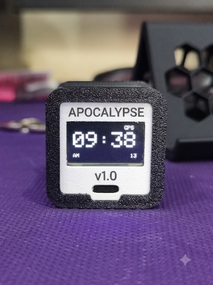
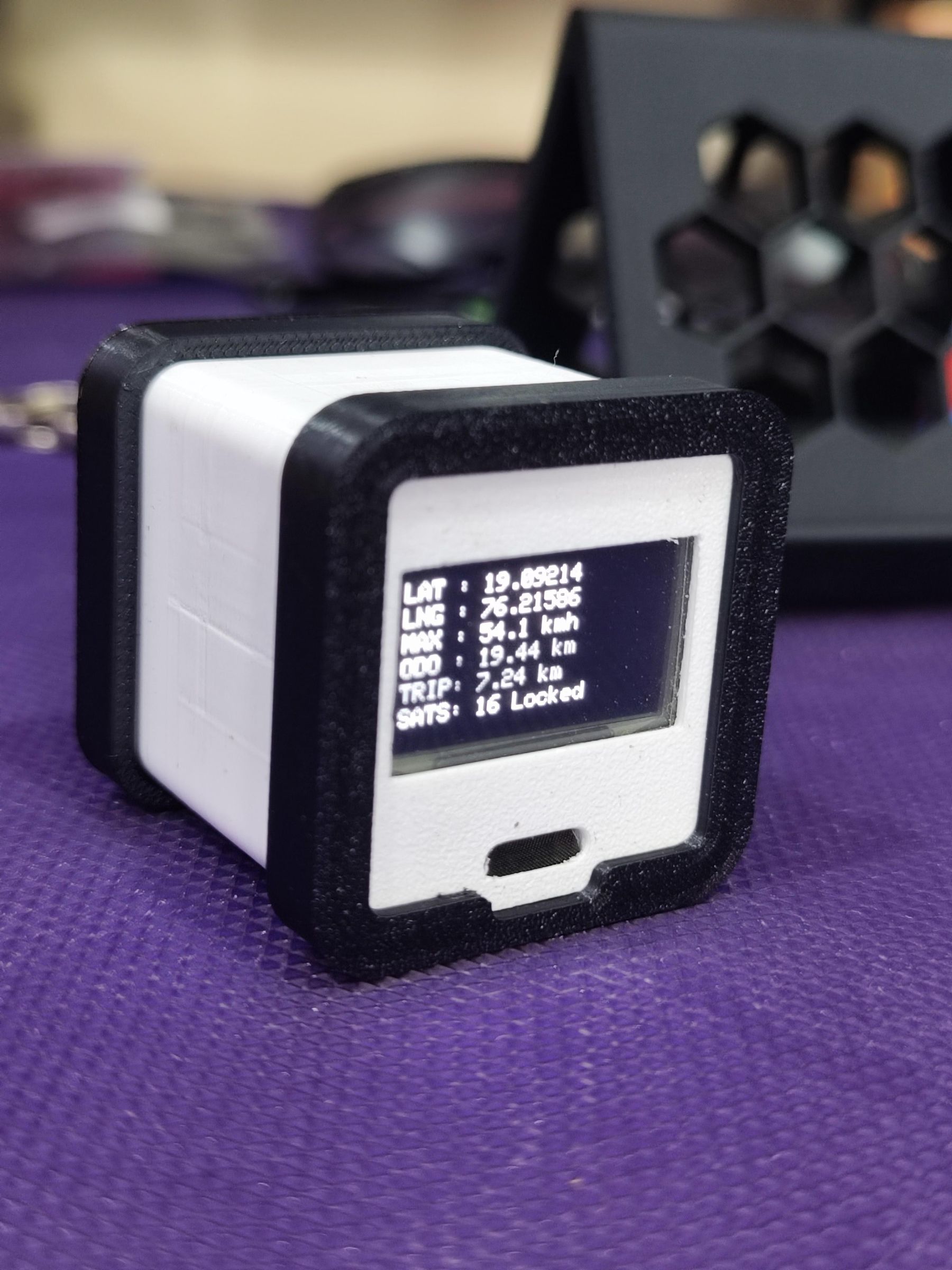
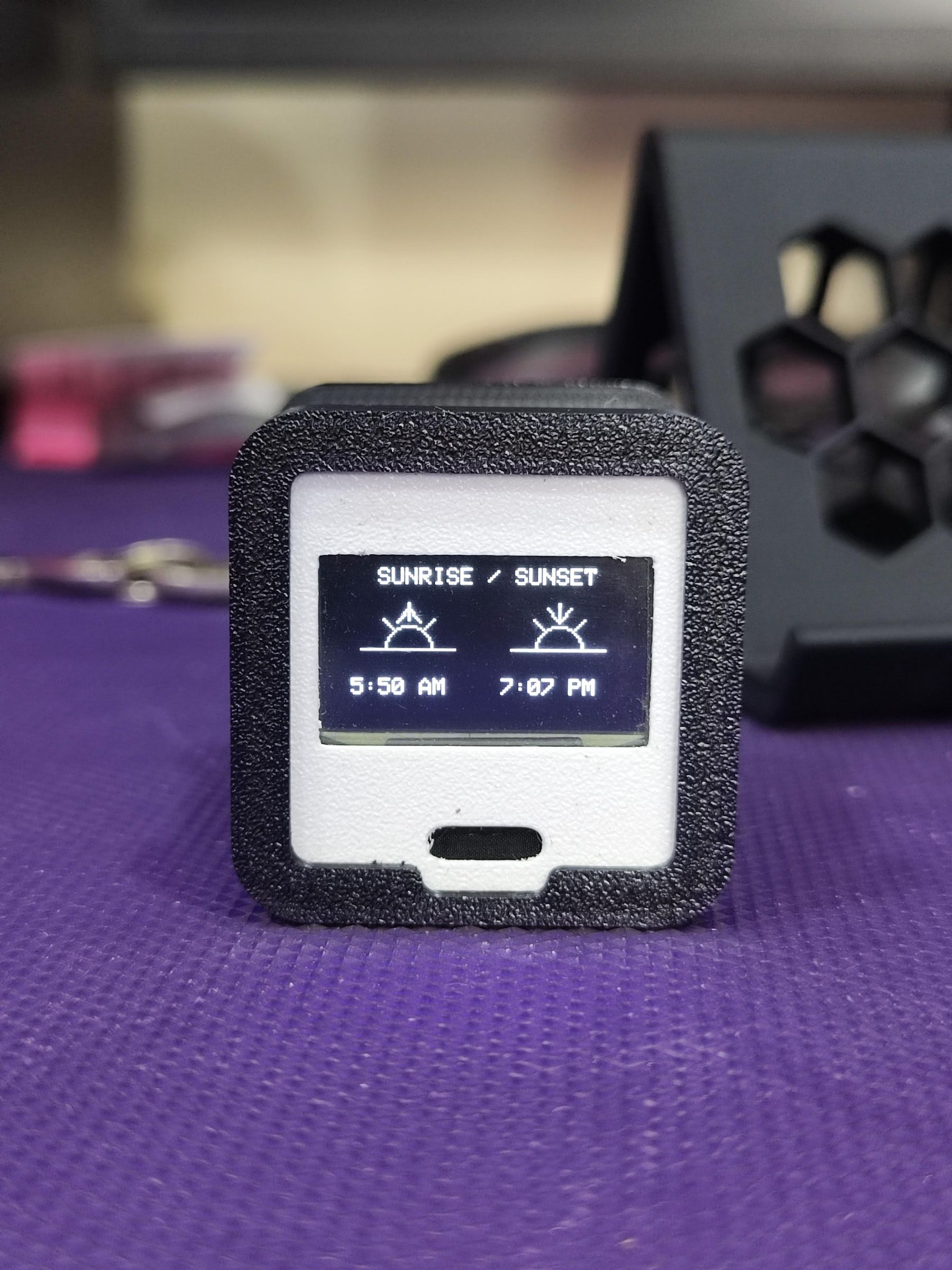
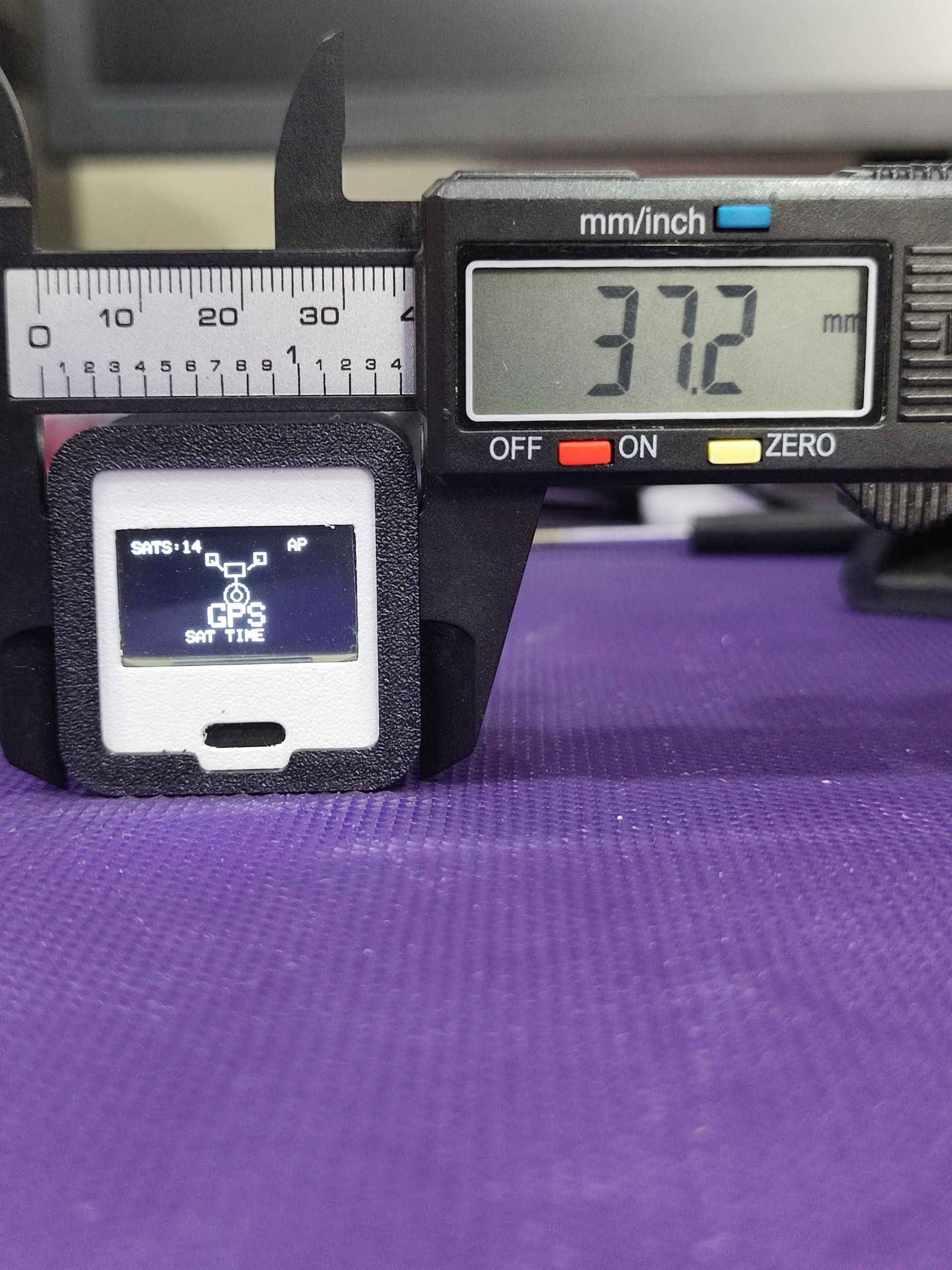
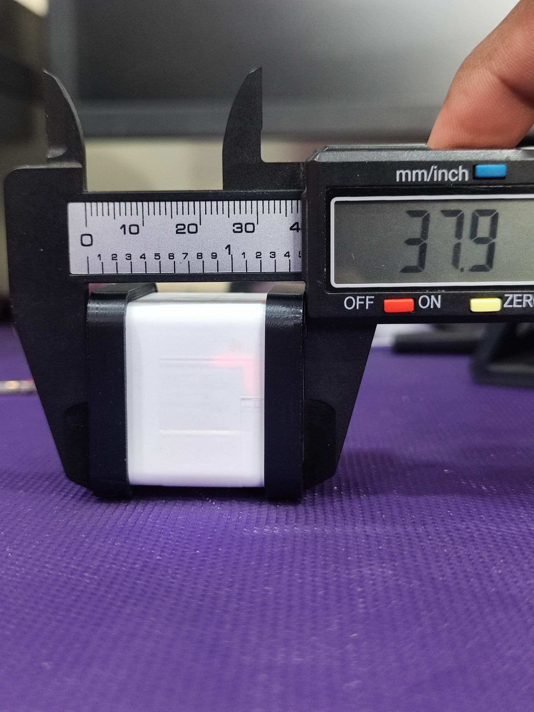
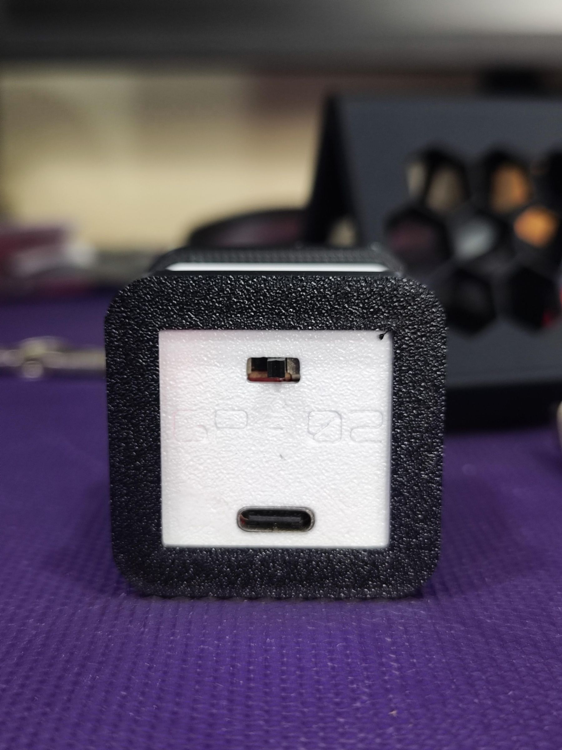
Imagine a scenario where the power grid is down, cellular networks are completely non-functional, and the internet is a memory. In a grid-down or survival situation, keeping track of basic reality—exactly what time it is, how fast you are moving, when the sun will set, and where you are located—becomes a massive challenge.
The Apocalypse Companion is a rugged, self-contained, pocket-sized survival device built to solve this exact problem.
Unlike modern smartphones or smartwatches, this device requires zero internet, zero cellular data, and zero external infrastructure to work. By leveraging the GP-02 GNSS (Global Navigation Satellite System) module, it communicates directly with overhead satellite constellations. It passively listens to orbiting atomic clocks to pull down highly accurate data anywhere on Earth completely off the grid.
Supplies
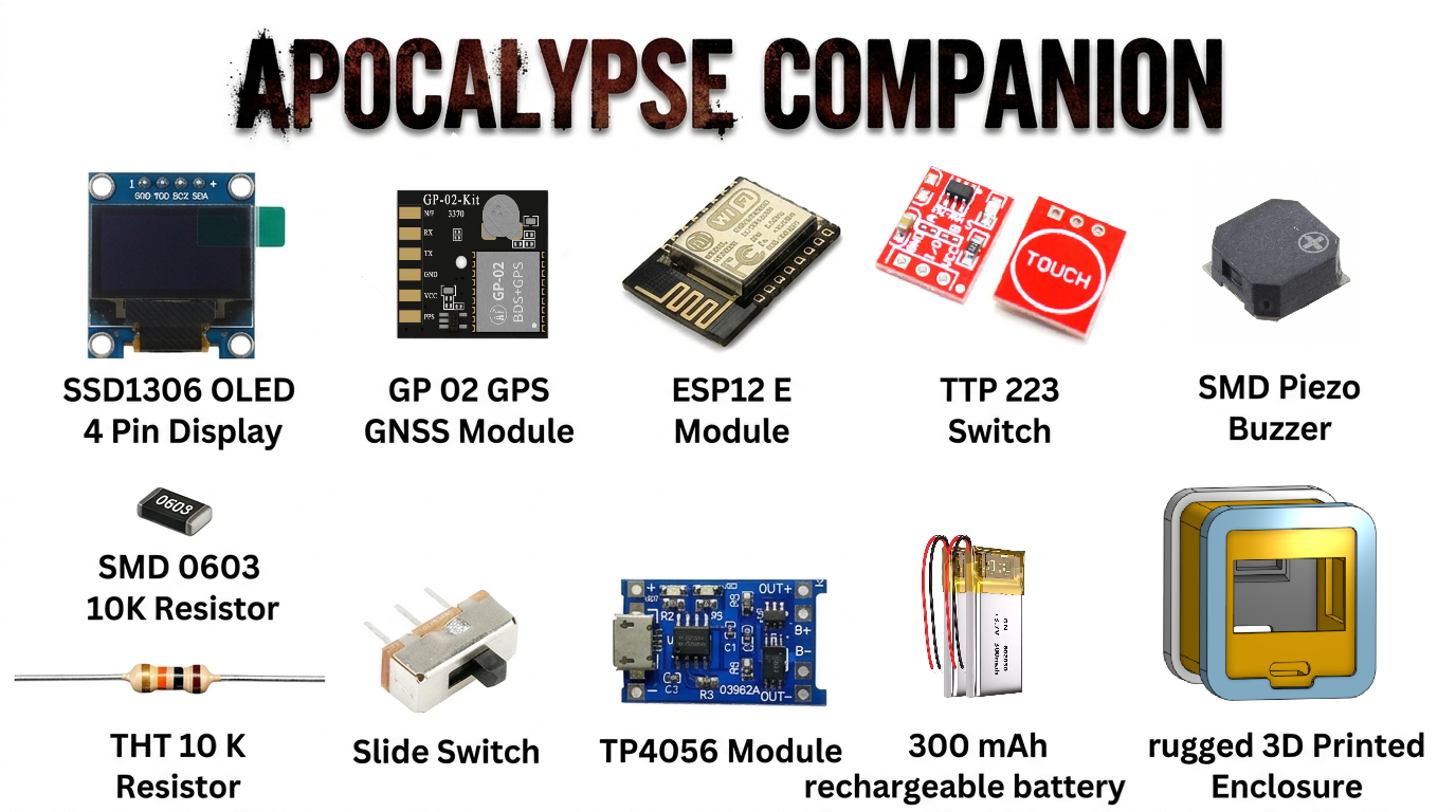
SSD1306 OLED 4 PIN DISPLAY (1 PC)
GP 02 GPS GNSS MODULE (1 PC)
ESP12 E MODULE (1 PC)
TTP 223 SWITCH (1 PC)
SMD PIEZO BUZZER (1 PC)
SMD 0603 10K RESISOR (1 PC)
THT 10 K RESISTOR (1 PC)
SLIDE SWITCH (1 PC)
TP4056 MODULE (1 PC)
AMS 1117 3.3v LDO (1 PC)
RECHARGEABLE BATTERY 300 MAH (1 PC)
3D PRINTED ENCLOSURE (1 PC)
SCHEMATIC
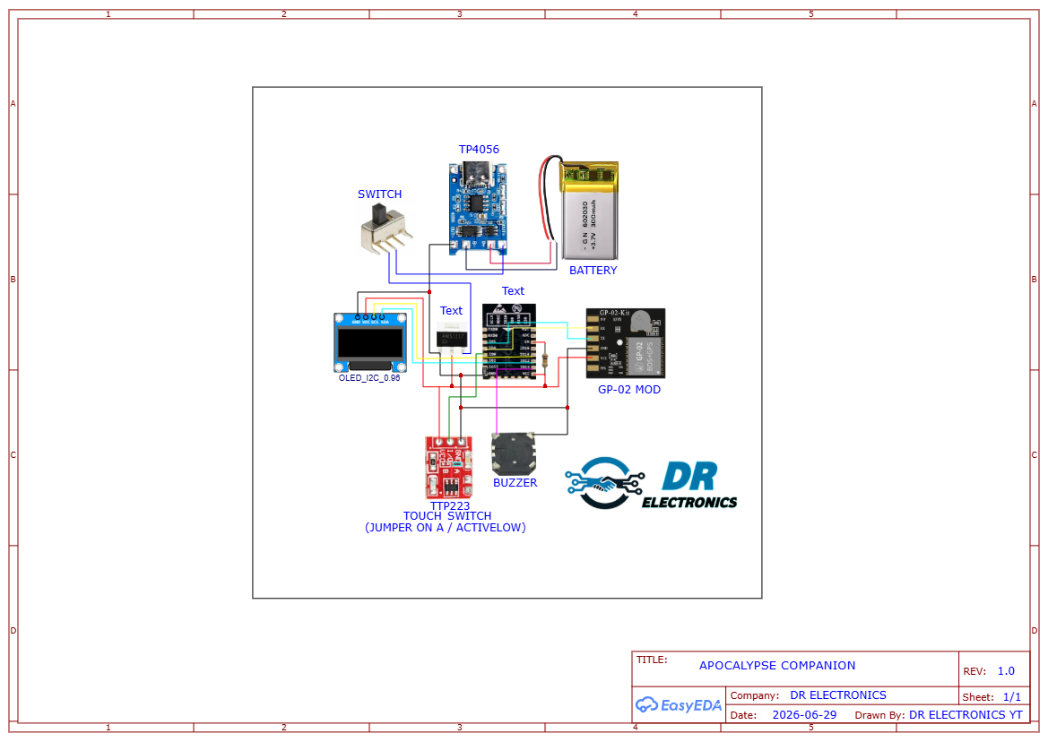
Connection Breakdown:
- GNSS Module (GP-02): Communicates with the ESP-12E via serial communication (TX/RX pins) to pass raw satellite data.
- OLED Display (SSD1306): Connects via I2C protocol (SDA/SCL) to display your coordinates, time, and speed.
- Touch Interface (TTP223): Acts as a digital switch connected to a GPIO pin to cycle through different display screens. (active low trigger)
- Power Management (TP4056): Regulates the 300mAh rechargeable battery safely, connected through a hard slide switch to completely isolate the power when turned off (crucial for long-term storage).
- Audio Feedback: A Piezo buzzer handles simple tones and alerts (like a satellite lock confirmation).
SOLDERING
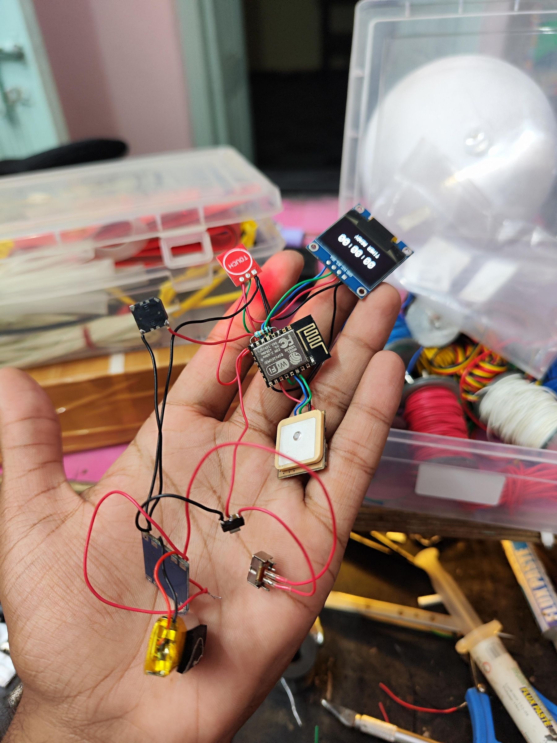
In this step, we will permanently mount our components and wire them up. Because an apocalypse device needs to handle bumps and drops, soldering is highly recommended over a breadboard.
To keep the build simple and prevent short circuits, we will use a specific color-coding system for our wires. This ensures that if you ever need to troubleshoot the device in the field, you can identify every line at a glance.
Wire Color Convention:
- 🔴 Red: Power (3.3 V/4.2V)
- ⚫ Black: Ground (GND)
- 🟢 Green: ( SCL AND RX AND BUTTON )
- 🔵 Blue: ( SDA AND TX )
ASEEMBLY
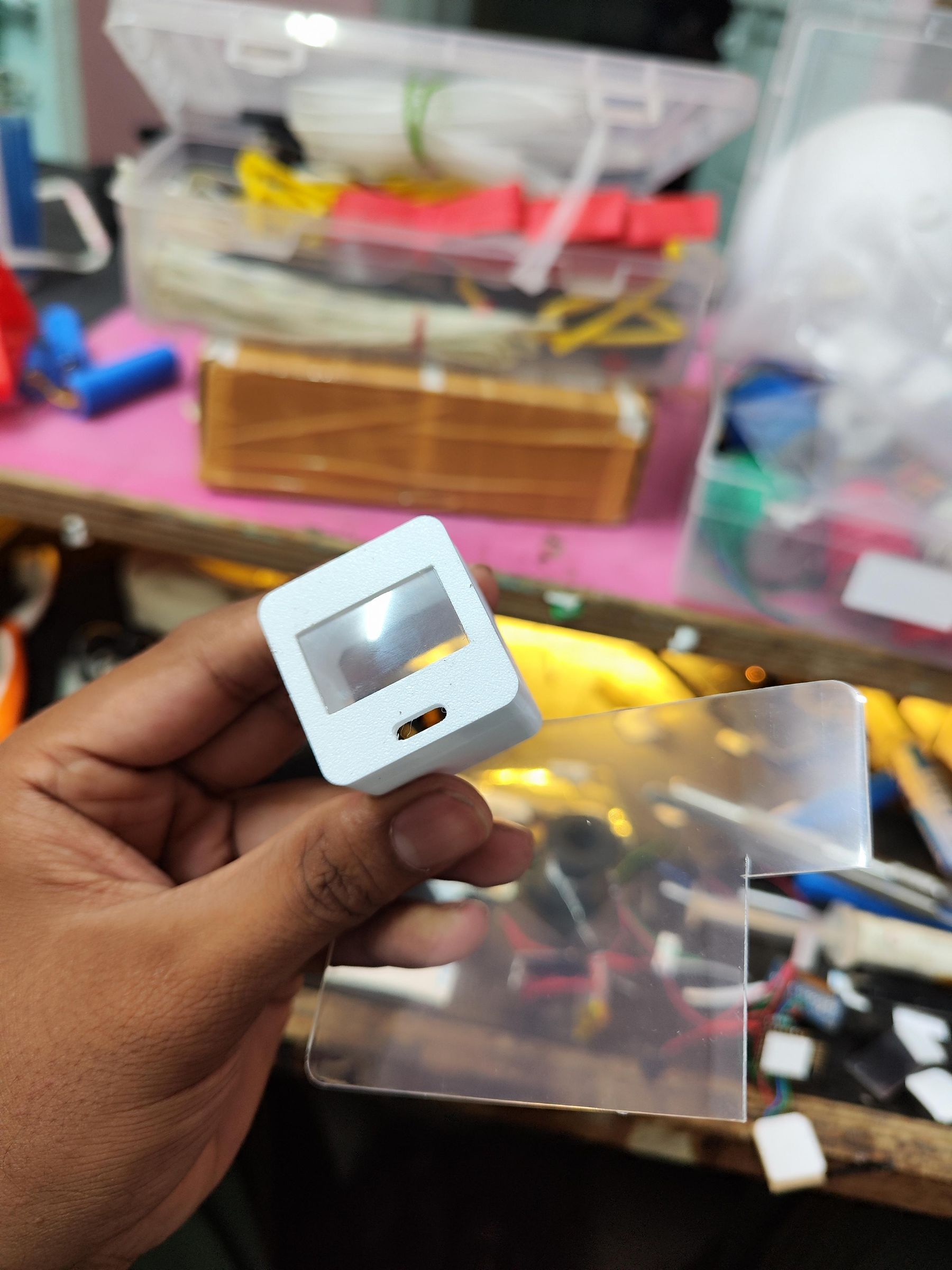
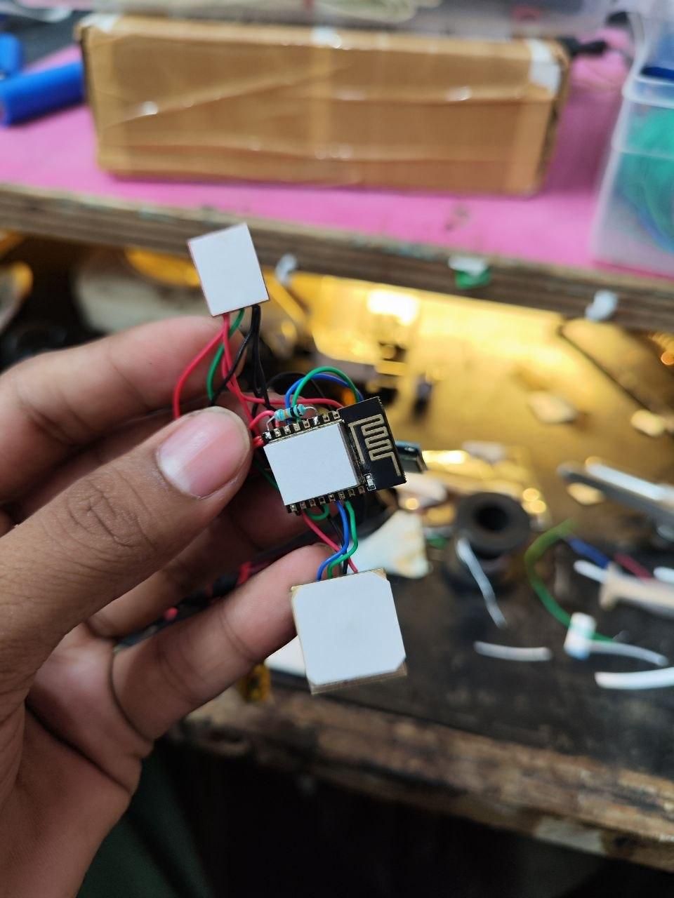
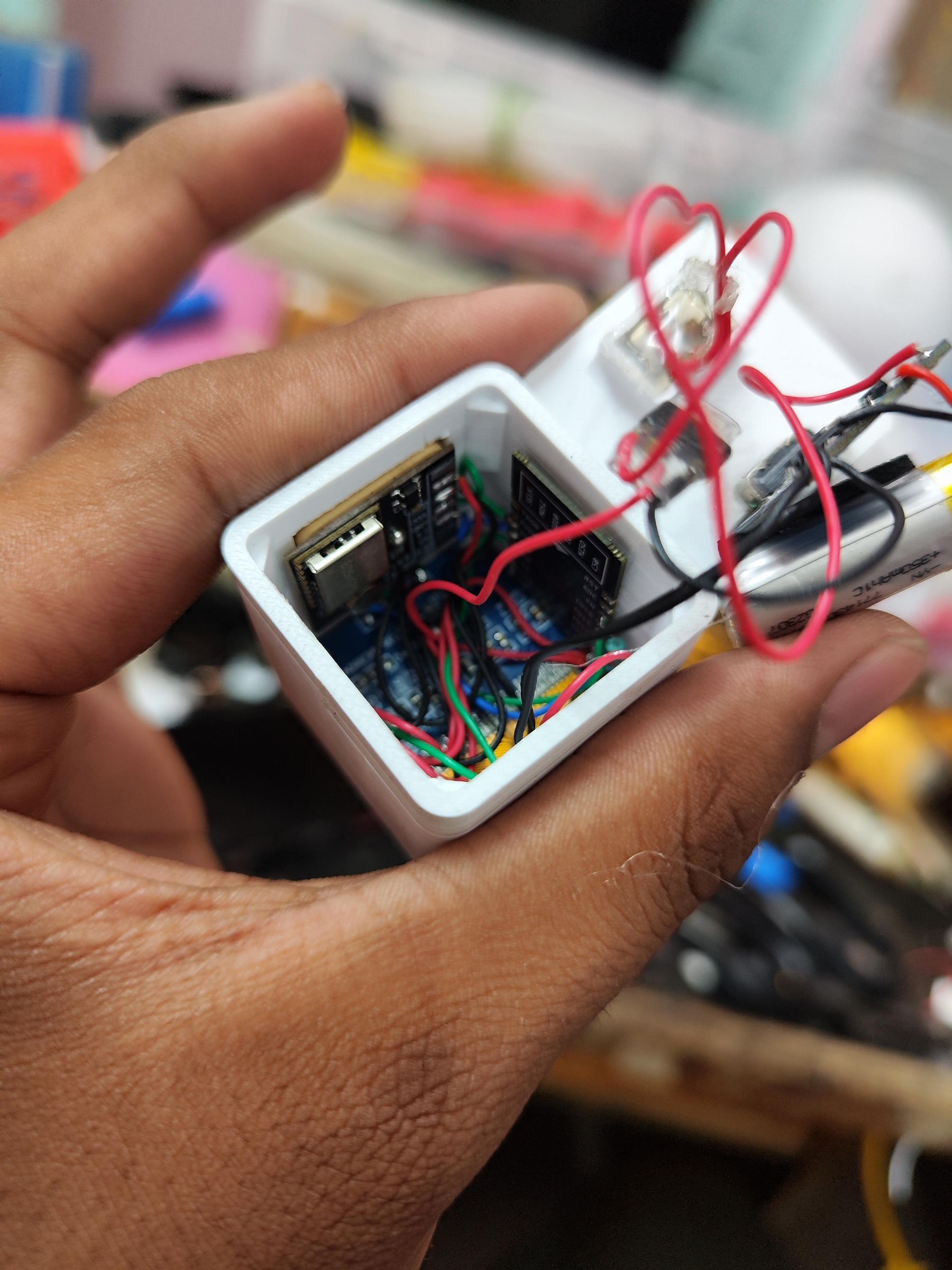
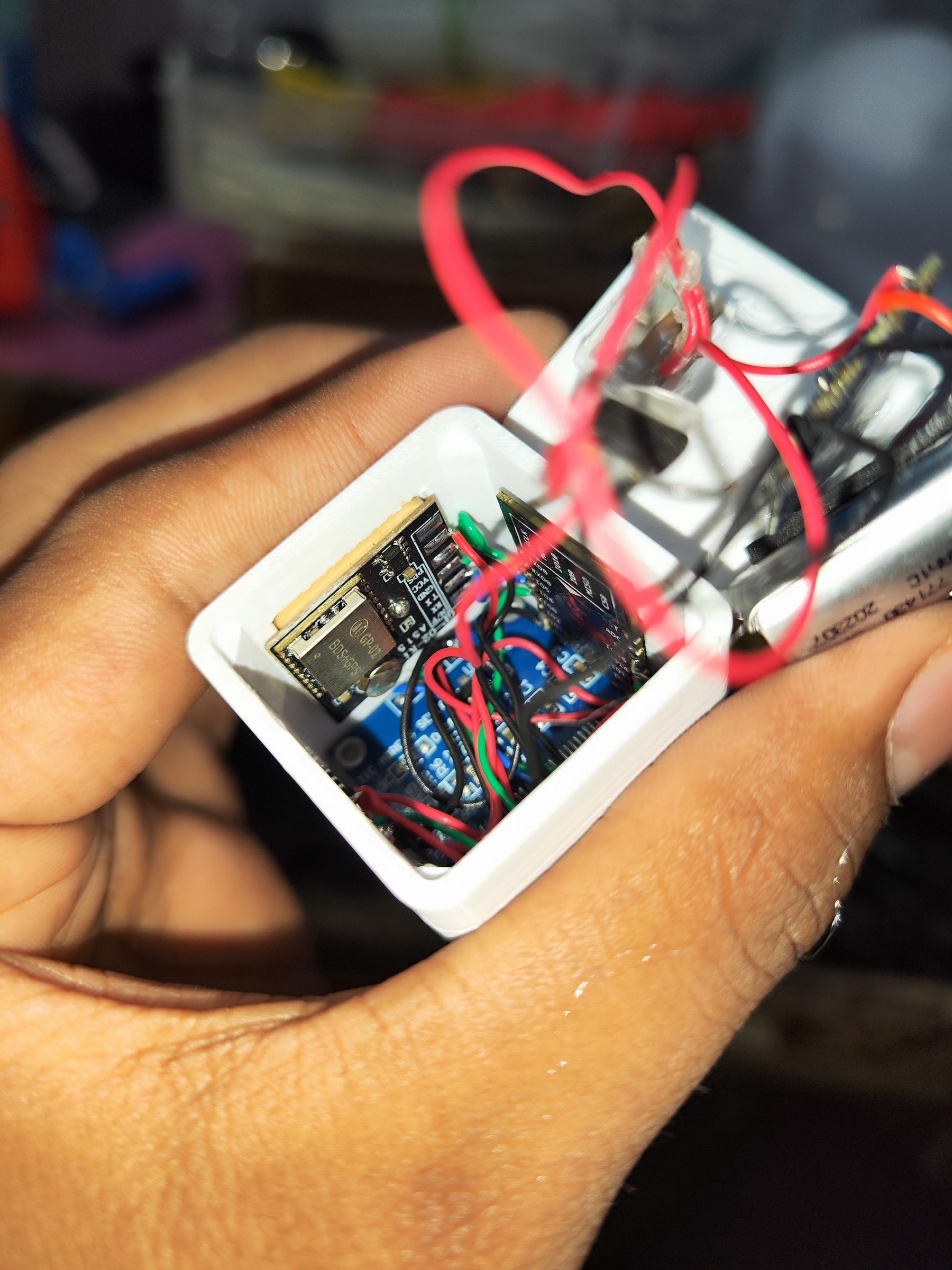
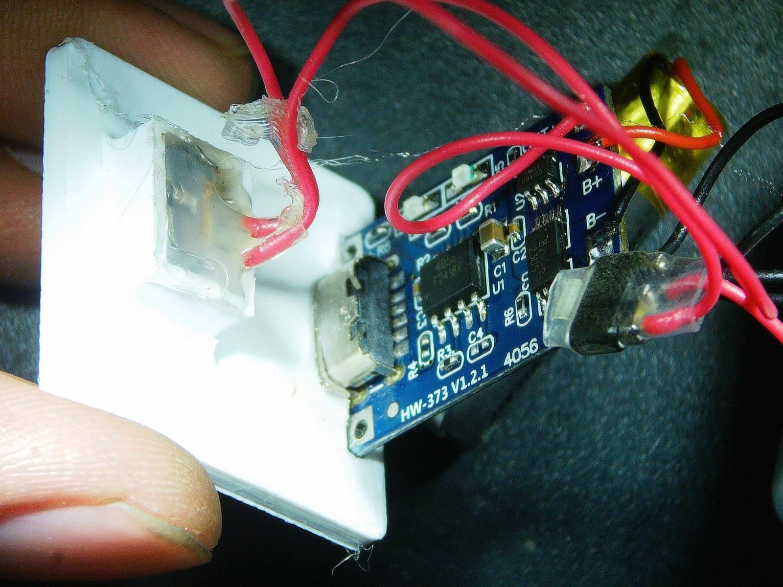
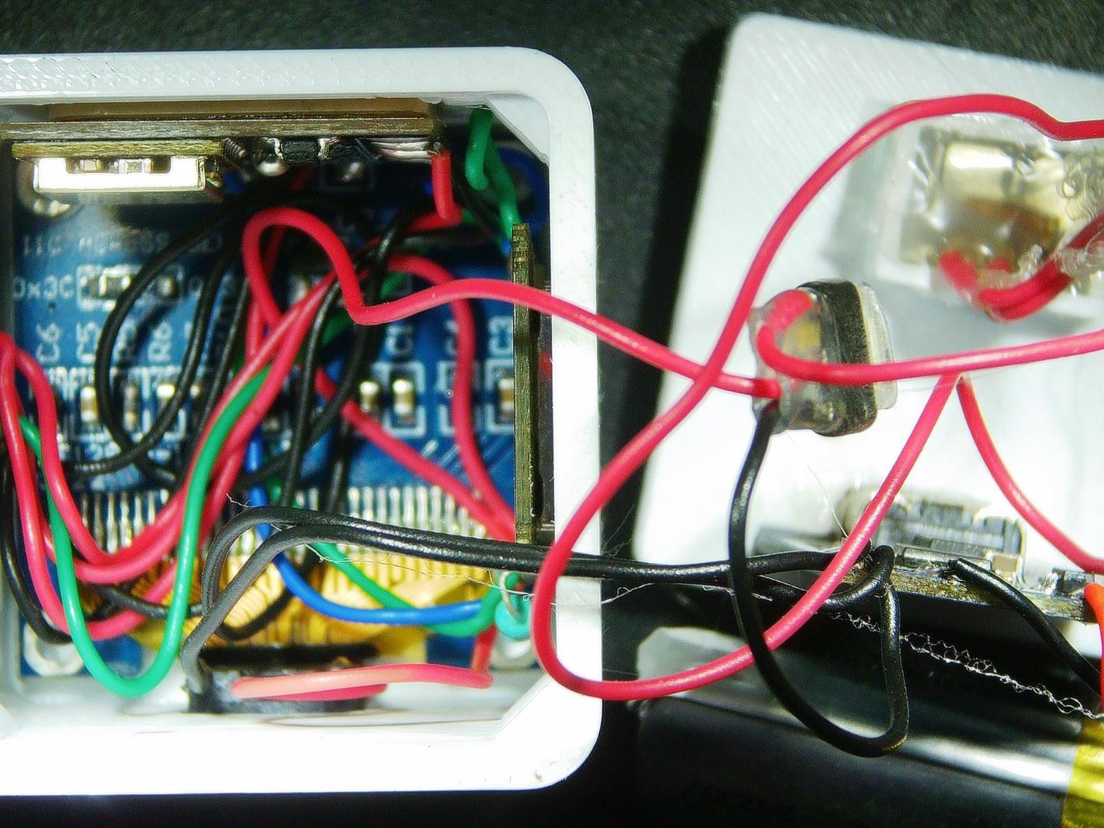
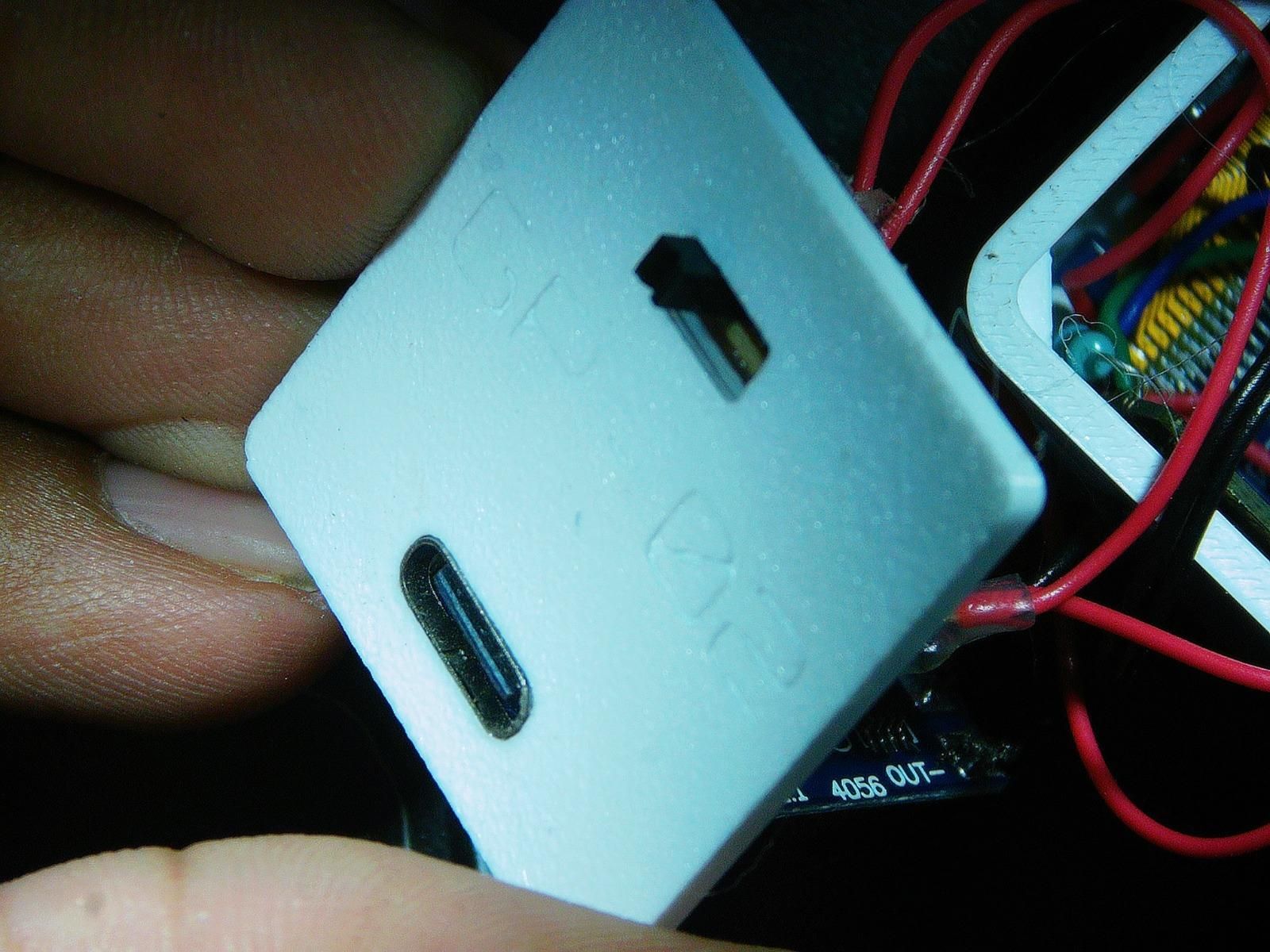
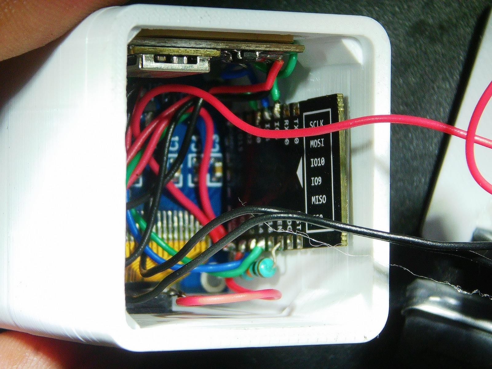
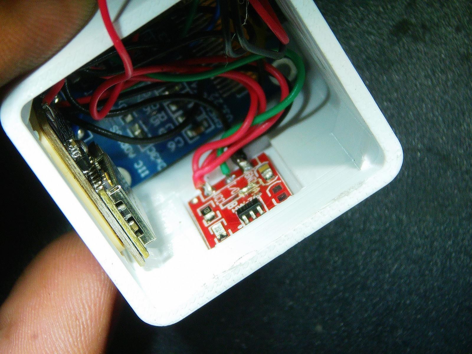
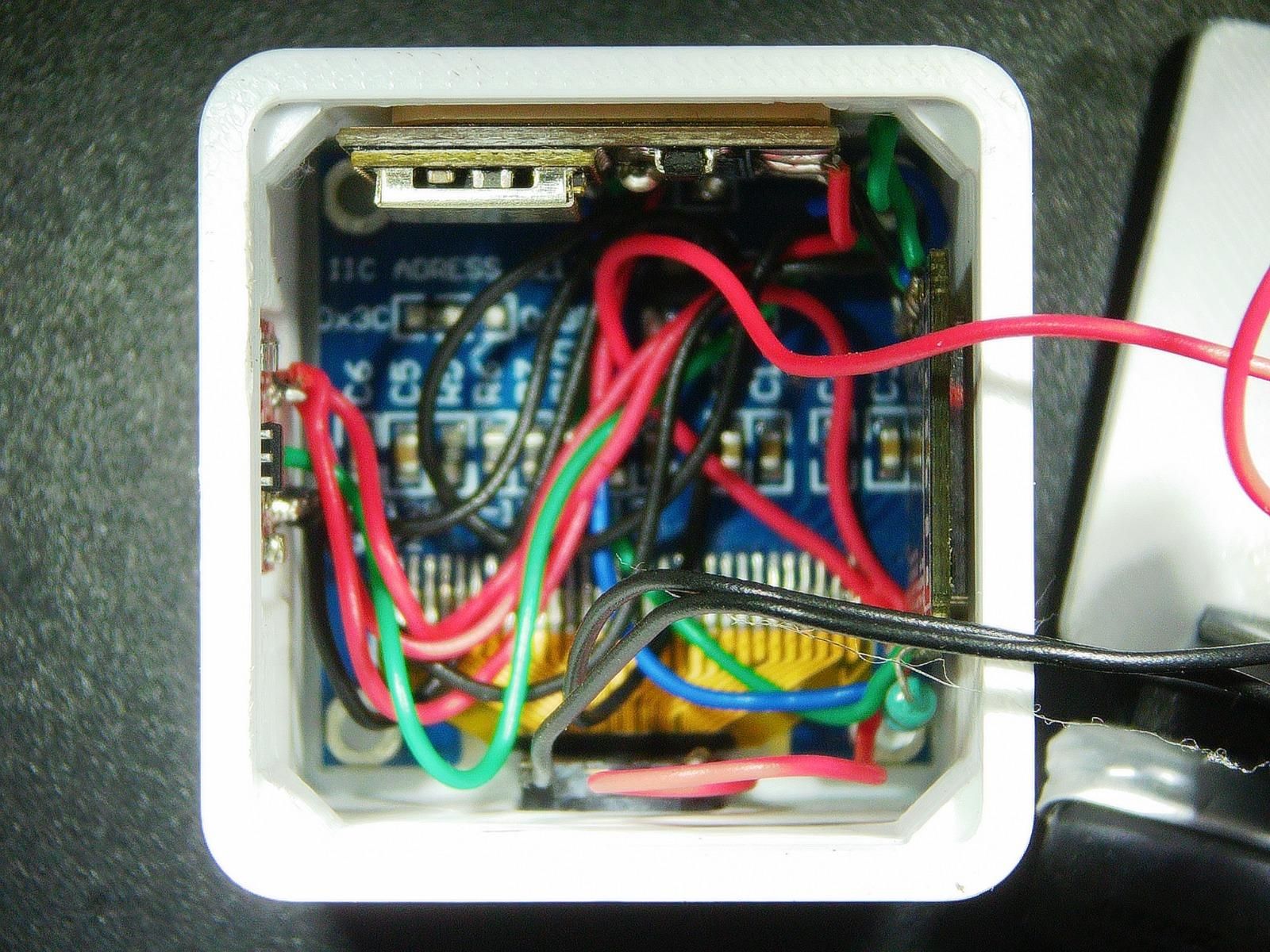
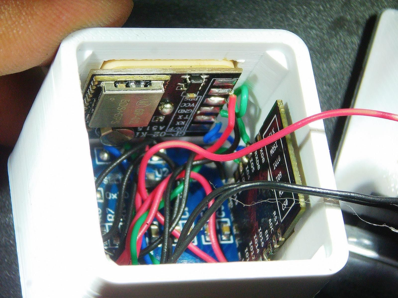
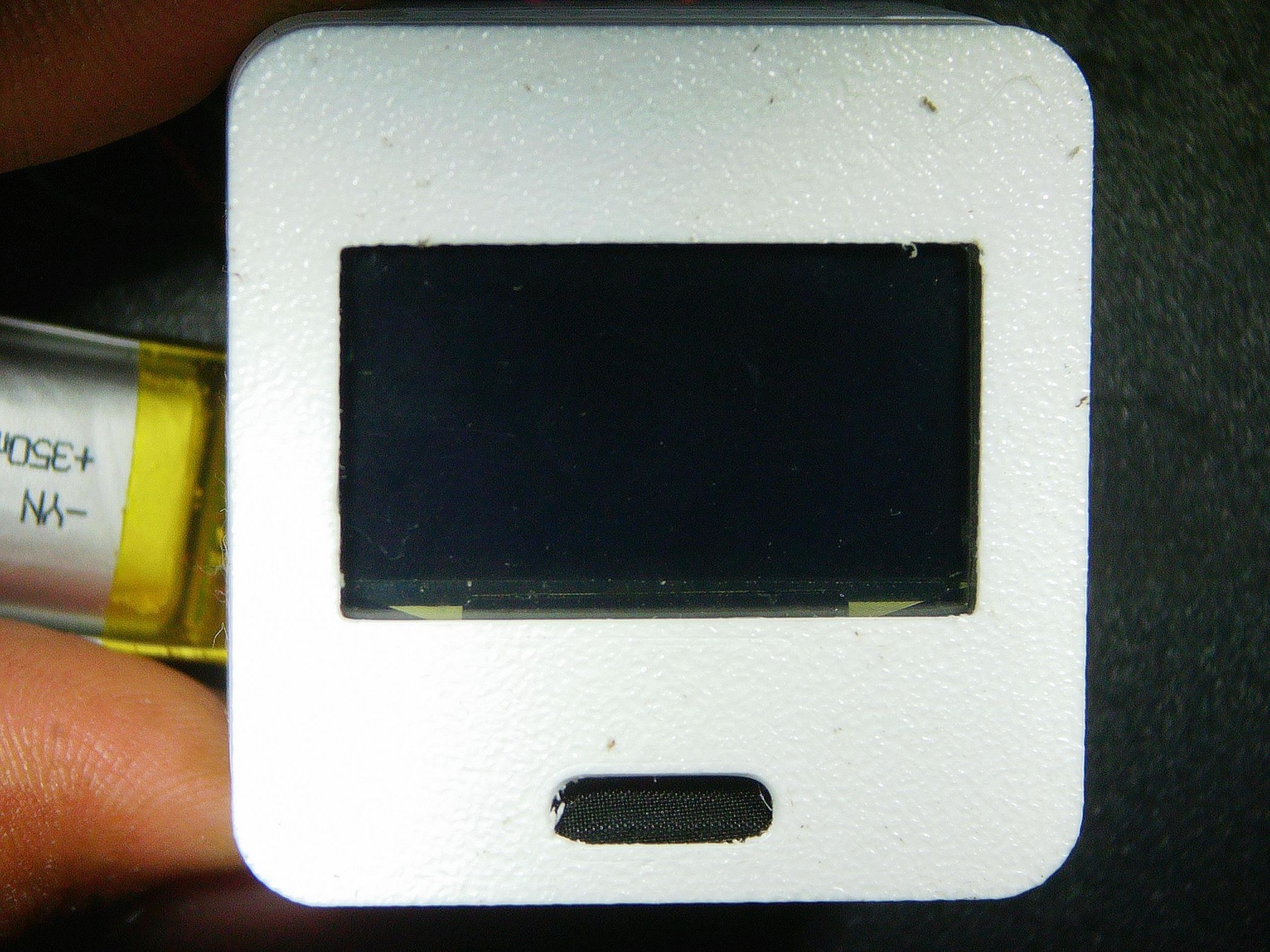
Apocalypse Companion is designed to be highly portable and pocket-sized, fitting all the components inside the 3D-printed enclosure requires a bit of strategy, a steady hand, and a little bit of patience.
Before pushing anything into place, double-check that all your solder joints are insulated (using heat-shrink tubing or electrical tape) so nothing shorts out against the other components inside the tight space.
Assembly Steps:
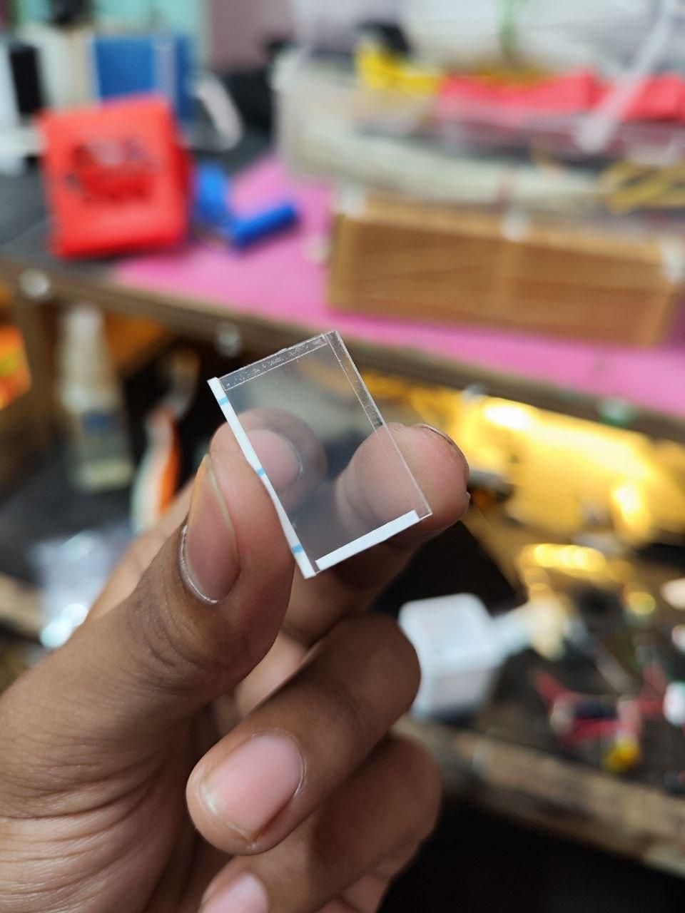
- Add safety glass: I used a plastic sheet which u can buy from the lamination shop , Cut the sheet as per the slotted space for display and add a double sided sticky tape on borders so it sticks and does not fall over while assembly
- Mount the Screen and Touch Button:
- Carefully slide the SSD1306 OLED Display into its front window cutout. Secure it around the edges using small strips of thin, high-bond double-sided tape.
- Place the TTP223 Touch Pad directly behind the designated touch area on the enclosure shell, securing it with double side tape so it remains responsive through the plastic.
- Position the Microcontroller and GNSS Module:
- Set the ESP-12E and the GP-02 GNSS Module into their respective slots.
- Tip: Position the GP-02 module so its built-in antenna faces outward (usually upward or toward the sky ) to ensure it gets the best possible line-of-sight to the satellites.
- Tuck the Power System and Battery:
- Snap the Slide Switch into back cover.
- Place a small piece of foam or double-sided tape on the back of the 300mAh LiPo battery to cushion it, then carefully fold the wires and layer the battery beneath the electronics. Ensure the TP4056 charging port lines up perfectly with the opening on the back cover of case.
- Close It Up:
- Gently tuck any remaining loose colored wires into the empty pockets of the enclosure.
- Carefully press the back cover of the 3D-printed case into place until it clicks secure down with super glue , while making sure no wires are pinched in the sems.
6. 3D Printable Files are available Here
PROGRAMMING
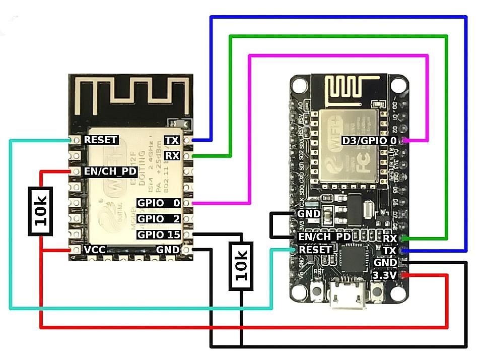
Instead of dealing with complex IDE installations, board managers, or hunting down library files, we can flash the Apocalypse Companion directly from a web browser using an Online Web Flasher.
How to Flash Your Device:
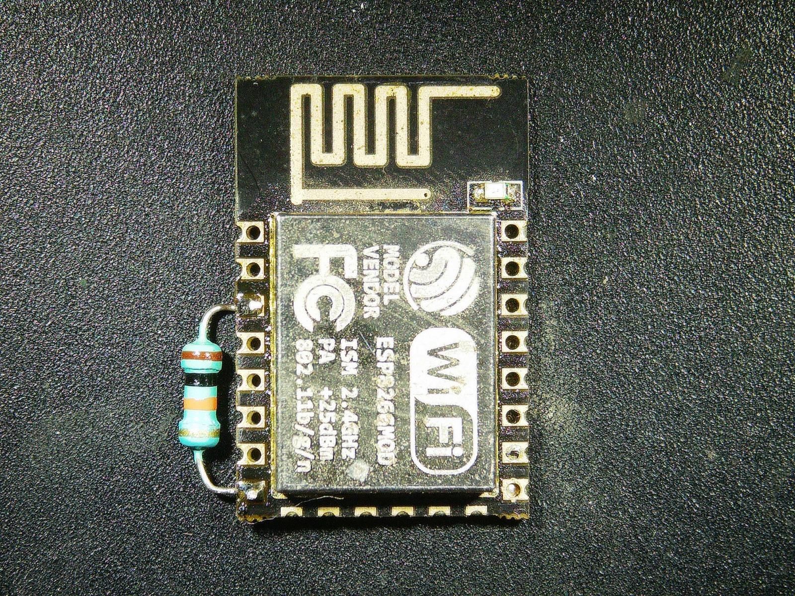
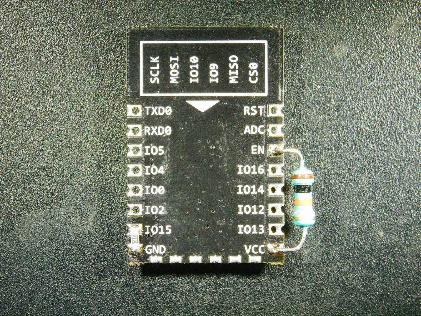
- Connect: Plug your assembled Apocalypse Companion into your computer using a data-capable Micro-USB cable.(Here we are using stand alone circuit for microcontroller so u need to program it before soldering anything , you can use esp12e/f programmer board or above shown circuit )
- Launch: Open the online flasher tool in a Web Serial-supported browser like Google Chrome or Microsoft Edge.
- Install: Click the ⚡ CLICK HERE TO INSTALL button below to open the connection window.
- Select Port: Choose the COM port assigned to your ESP 8266 (usually listed as CH340 or CP210x) from the browser pop-up and click Connect.
- Flash: Select Install and wait for the progress bar to reach 100%. Once done, your device will reboot and immediately begin searching for satellite signals!
🛠️ Troubleshooting Tip: If your computer doesn't recognize the device when plugged in, you likely need to install the common CH340 driver or CP210x driver so your browser can talk to the microcontroller's USB chip.
USER GUIDE , ERRORS and WEBSERVER
- BOOT ISSUE : After boot if shows scrolling message GP-02 Not connected ,connect and reboot . This means the gp02 is not connected or RX/TX wires are connected in wrong polarity , the display will keep showing error and wont proceed unless solved .
- CONNECTIVITY CHECK : after boot a 60 sec Timer will start in that time if no satellites are found it will move to WIFI and check for WI-FI connectivity for 15 sec if fails to connect to WI-FI Device will reboot and follow same pattern again . If any satellite is found it will start the main loop and also check for WI-FI in background without interrupting. And take weather forecast update from the provided API ( at 60 sec timer you can short touch button once to skip and start the loop)
- TOUCH ACTIONS : Single short tap changes FACES and to lock the face long press touch for 3 seconds and you will here double beep and a dot on right top corner , to unlock face do short touch once . to enter timer locate to timer face and long press to enter time settings or set timer from webserver.
- API KEY : get your locations API KEY From OPENWEATHER . Tutorial to get API KEY . and paste it in webserver created by the device and save it if everything is correct it should show weather data .
- WEBSERVER : Here is the offline copy of WEBSERVER open it in chrome or edge to view the copy without uploading code . The link shows approximate look of webserver.
- Watch full video: https://youtu.be/Zf_uiDE4K_s?si=XOk7JGMIdWOY9PFs