ARDUINO - Police Car

Hello! My name is Aarav, and I built a police car with the help of electrical components and of course, the ARDUINO UNO. The idea behind this car came from my love of high-tech cars with advanced features. As you explore this Instructable, you will see how my car differs from regular Arduino Uno cars. That being said, welcome to my Arduino Police Car Instructable!
Supplies

For this project, I used:
- Arduino Uno - $27.60
- Small Breadboard - $10.99
- Breadboard - $8.09
- H-Bridge - $12.85
- Two Motors - $7.29
- Distance Sensor - $2.00
- Capacitors (I used 100uf & 10uf ) - $10.69
- Resistors - $16.64
- 555 Timers - $15.54
- IR Remote & Receiver - $2.23
- Buzzer - $0.57
- LEDs (Mostly red and blue LEDs) - $0.20
And of course:
- Appropriate length wires
- Cardboard
- Arduino Software
- Car Chasis - Custom Build
Before you continue, place your arduino and breadboard on your car chasis. Ensure they are in place and do not move around, otherwise, wiring will be a complete mess.
Flashing Police Lights


What differs a normal car from a police car (that's not the large text reading "POLICE" on the side)? That's right! The Flashing Police Lights.
For this step you will need:
- 2x 555 Timers
- 3x Red LEDs
- 3x Blue LEDs
- Wires
- 2x 330 Ohm Resistors
- 2x 1M (Million) Ohm Resistors
- 10uf Capacitor
- 100nf Capacitor
How it Works:
This circuit may seem complicated at first, but is very simple. The heart of these police lights are the two 555 timers. Essentially, I built two identical astable circuits, but both configured at a different frequency. The first 555 timer IC, uses a bigger capacitor and so it takes more time to toggle the output. The second 555 timer IC uses a smaller capacitor and so it toggles the output very fast. Whenever the red LEDs turn on, the blue LEDs are off, and vice versa. This pattern occurs very fast, which is what causes the rapid visual.
Refer to schematic
Setting Up IR Sensor

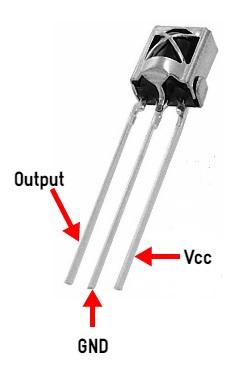
Each and every remote outputs a different infared signal. This is why it is extremely important to understand which signals to configure in order to properly control your car. For my project, I used a TV Remote.
For this step, you will need:
- IR Remote
- IR Receiver
- Arduino Uno & Softawre (Sketch)
- Breadboard
ENSURE YOUR ARDUINO SOFTWARE HAS THE IR LIBRARY.
Firstly, refer to the first image, the set up on a breadboard for this step is temporary and fairly simple. Once you are done wiring the sensor, you can check which buttons send out which signal using the inbuilt code in the IR Receiver Library. Simply go to New >> Examples >> IR-SetUp.
This step will help you build your if-statements in step 5.
Don't Forget to have enough buttons for functions such as forwards, backwards, left & right
You can move on to the next step once you know which signals correspond with the buttons you wish to use.
Turn Signals
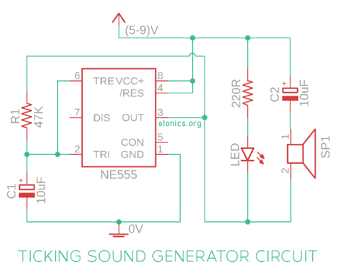
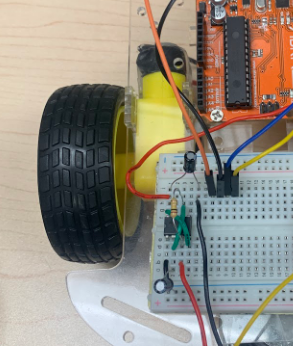
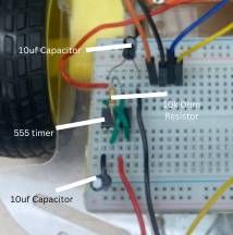

As I mentioned before, I built this car to have as many modern car features as possible. What better than to add turn signals with a functioning version of its infamous "tick-tock" sound.
For this step you will need:
- 2x 10uf Capacitors
- 555 timer
- Buzzer
In this circuit, 555 timer IC is configured to work in astable / bistable mode. It means that voltage at the output of 555 IC continuously toggles between 0V and Vs (The supply voltage, in our case its 5V). Each time there is a transition in the output voltage from 0V to Vs or from Vs to 0V, the diaphragm of the speaker moves rapidly. This movement generates a tick or tock sound depending on whether the diaphragm is moving up or down.
This step also includes LEDs which are the visual indicators. Avoid just placing the LED on your breadboard, and find MALE/FEMALE wires to extend the legs of the LED. This will allow you to properly place the LEDs when it comes to the final step.
The code for this is simple:
CAS (Crash Avoidance System)


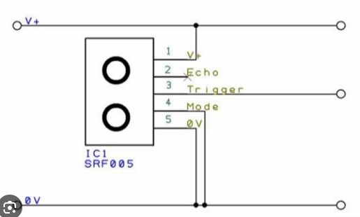
If you refer to the main code attached to this instructables, you will see multiple custom built functions which control how the wheels on the car move. The Crash Avoidance System (CAS) utilizes the stop(); function. This function turns off all the motors, to restrict movement.
For this step, you will need:
- Distance Sensor
- Arduino Sketch
The code for these fuctions look like:
Firstly, wire the distance sensor correctly, and ensure you are using as little space as possible on your breadboard. Once you have the appropriate ECHO and TRIG pins, you can use this code to get your CAS working:
This code uses an ultrasonic sensor to measure distance. The TRIG_PIN sends an ultrasonic pulse, and the ECHO_PIN measures the time it takes for the echo to return using pulseIn(). The duration is converted to distance (in inches) with duration / 148.0. If the distance is 1 inch or less, the stop() function is called to halt the system.
H-bridge & Code
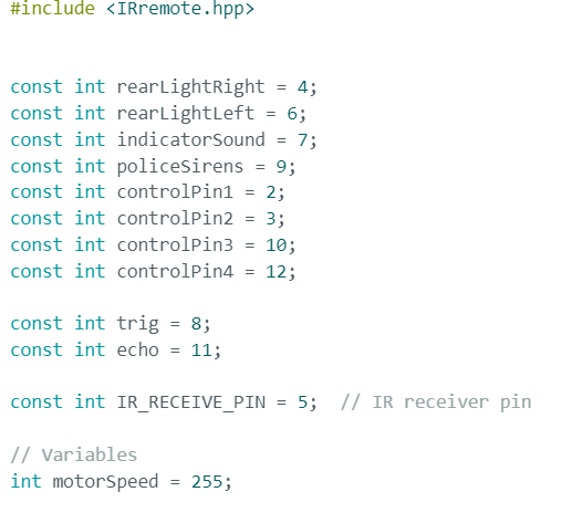

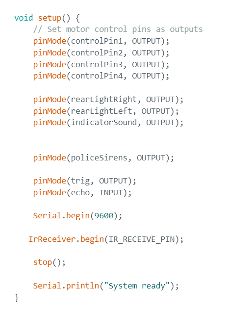


Now that we've explored the fuctions, you can start building your own code!
Firstly, It is essentially you include the IR library in your sketch, otherwise, none of the IR related functions will work. When you wire your H-bridge to the Arduino, refer to the H-bridge schematic. Essentially, you're H-bridge has two VCC, and four GND pins. The other pins are for Analog and Digital Inputs. In this case, I want the speed to me at max no matter what function is called. So, the analong inputs can be connected directly to power. The other remaining pins are the control pin. When you wire the control pins, remember what Arduino pin you connect it to. You will need it for your code! While you're at it, also see which pins your Distance Sensor, LEDs, buzzer, and Police lights connects to, you will need it in order for the previous steps to work.
Refer to the first image to see how to initilize these variables.
Secondly, you must complete the void setup(). This step declared whether the pin you connected your components to should output power, or input data.
Thirdly, the first part of the void loop should look like the fourth image. I used a modified version of the indicators in my code. The fifth image contains all the seperate if and else-if statements in order to correctly call on my movement functions. Remember, my IR Signals would e different from yours.
Downloads
Final Step


All that's left for this step is to build your desired frame!
For this step, you will need:
- Cardboard (optional)
- & whatever you want to add
I chose to build a frame using cardboard. I made a small cut out in the front for my distance sensor, as well as one in the top for my police lights.
For the police lights, I had two seperate wires, one going into a different GND pin, and one going in to PIN 8.
That's all! Have fun building your Arduino Police Car!