Adaptive Game Controller for Cerebral Palsy
by Daniel Sanchez in Circuits > Assistive Tech
1772 Views, 4 Favorites, 0 Comments
Adaptive Game Controller for Cerebral Palsy

Controller #1 (Diplegia)
This controller is designed to use their fist closed and they can slam or touch the button inside the tape outside to send a signal to the Makey Makey. Its buttons can also be switched around for the user's preference and only requires you to change the buttons and connection on the Makey Makey.
Controller #2 (Quadriplegia)
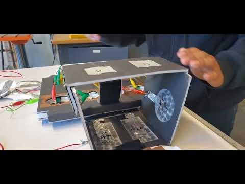
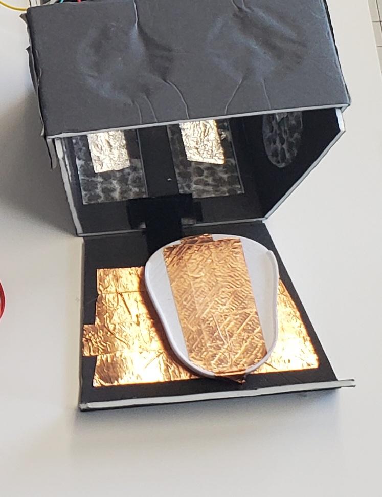
This controller is designed to be used by one foot and they can place their foot on the 3D printed part with a bearing to turn easily to the buttons inside the box. This box is also very compact and can be taken anywhere. Also, it can connect with the first controller to provide more stability.
The idea behind these controllers was to make them durable, clean, and compact so that the wires wouldn't get in the way of the gaming experience so that you can take it anywhere with you, and really easy to set up.
Supplies
Game Controller Base Foam Core (Diplegia)


- Draw a 12''x12'' square on the 1/2'' foam core
- Cut out the 12''x12'' square
- Then draw four circles on the top and three rectangles on the bottom as shown in the picture above
Cut Out the Drawings and Make Channels


- Cut out the circles and rectangles at an angle so that it's like a dome shape as shown in the first picture
- Cut out a space for the Makey Makey so it can fit in.
- Then make channels in the box that go to each button as shown in the last two pictures above
- You're then going to want to cut through the entire circles and rectangles except for the Makey Makey space
- Lastly using sandpaper smooth out all the cuts like the circles and rectangles in the box to look clean.
Cutting Top and Bottom Covers for Controller Base


- Next you're going to want to cut out another 12 6/8''x12'' square using 1/8'' inch foam core.
- Then line it up under the base, draw the four circles and two rectangles, and cut through them.
- Then you're going to want to make sure that the 12 6/8'' length of the square to be sticking out from the top of the base.
- Next you're then going to cut out but not all the way a 1/8'' in the part that is sticking out to create a joint as shown in the 2nd and 3rd pictures. (Once you cut through it you can peel it off with your fingers or however you like to create the gap/joint)
- Then hot glue the small end of the square that is separated by the gap to the side of the box to then be able to open and close as shown in the last picture.
Finishing the Box to Do Setup the Wires


- When you're done then cut out another 12''x12'' square using 1/8'' foam core and hot glue it to the underside of the base to cover the holes at the bottom.
- Then make sure when you put the Makey Makey in the space for it that the USB cable port is facing outwards from the box instead of the inside so that you can cut through the box to make a hole as shown in the 2nd picture above.
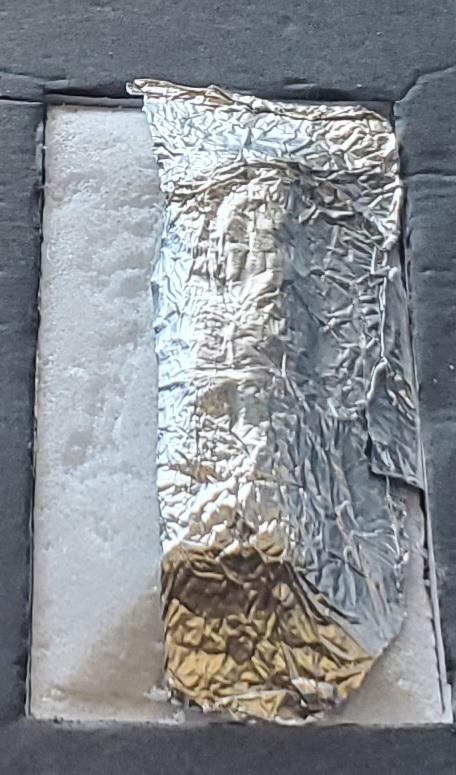
- Then you're going to want to hot glue a strip of tin foil in the middle space of the buttons and use an alligator clip to clip on that strip, once that is done then it should look like the last three picture above.
First 3D Printed Part and Setup


- Once everything is set you're going to want to go to the first Fusion 360 CAD link and 3D print the model.
- Then you're going to want to cut through the 1/8'' top and the 1/2'' base of the controller but not the bottom piece of foam core.
- Then hot glue and place the 3D printed part in that space as shown in the first three pictures. (Note* the 1/8'' foam core top might be hard to close with the new part added but will work to keep it closed.)
Wiring and Tin Foiling the Buttons


- Then using the buttons you removed from the base in step 2 you will wrap half of the bottom part of the buttons and the middle part of the top of the buttons as shown above.
- Once you're done you can label the four circles left, right, down, and up and the two rectangles labeled as space and left click.
- Then this part is up to the user on how to wire and place where each button goes but we'll use the setup from above as an example.
- The buttons from left to right will be up, down, left, and right, and the other buttons from left to right will be space and left click.
- Next you are going to make sure that each alligator clip is connected to the corresponding place on the Makey Makey where the strip of tin foil is in the button area and also use the short alligator clips for these connections.
- Additionally there will be a ground wire that should be longer and that will also go through the channels and out through another hole in the box as shown in the 3rd picture above.
- Once you have wired everything up, you're going to cut little strips of duct tape and put them over the channels to keep the alligator clips from coming out. Once you're done close it up and it should all fit in nicely.
Using Copper Tape and Adding Grip


- Then you're going to use the copper tape and apply it around the buttons and then connect the alligator clip that is sticking out of the box from the last step, the ground alligator clip as shown in the picture above. (Note* the copper tape needs to be touching the other two buttons for the ground clip to work for those as well.)
- Next you'll want to hot glue four times under the controller by the corners and when the glue is a little cool flip the controller and let cool off so that it's even and repeat this process again.
- Lastly you'll want to add two strips of Velcro that are 6'' long and a short piece on the top as shown in the last two pictures above and you're done!
Game Controller Add-on (Quadriplegia)


This is now a new game controller add-on for Quadriplegia (requires one foot to use)
- You're going to want to draw 6''x6'' squares as shown above
- Then you're going to draw and cut out a space for the buttons you created earlier and place them inside to see if they fit in tightly.
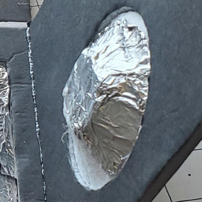
- When you do that remove them from their space and add strips of tin foil with one edge sticking out, you'll use that later to clip in the alligator clips( Note* do this for all the buttons)
- Then cut out a 1/8'' gap in between the squares like in the picture above and hot glue the sides at an angle in the 3rd picture.
- Then you want to cut out a piece of foam core that will connect the two sides together as shown in the last picture. (Note* when you cut out the piece that connects the sides you'll want to cut 1/8'' inch off the edge of the top where the other square is in the last picture)
Adding Velcro and Closing It Up


- The box should look like the first picture if the last step was done.
- Then add two Velcro strips that are 6'' long and place them in the empty square and two little strips on the top of the piece as shown in the 2nd and 3rd pictures.
- Lastly It should close like the last picture above
Add Another Foam Core Square


.jpg)
- You'll want to start by using the shape of the box and place it on a piece of foam core and draw the shape to cut out the desired shape like the one above.
- Next you're going to want to make sure that the piece is a little long like you did in step 3 and have a 1/8'' gap so that it can fold and close
- Then you're going to want to add a little guard like the picture above so that the foot doesn't go back
- Lastly it should be able to close like the picture above
Adding Second 3D Printed Part and Copper Tape


- In this step you're going to want to 3D print the second Fusion 360 CAD link and with the bearing from the supplies you'll want to place the 3D printed part in the bearing. (Note* if it doesn't want to go in place use sandpaper to smooth out the piece that needs to go in until it fits.)
- Then with the other part you printed that comes along you can place it anywhere you'd like within that area. For this case, I'll use the picture above as an example.
- Put the circle in the middle right section on the foam core, draw a circle around it, cut the foam core not all the way, and place it in the spot with hot glue.
- Then use multiple strips of copper tape to cover everything as shown above in the last picture.
Add More Copper Tape


- Make sure when you add the copper tape that it connects it to the circle part as well
- Then cover the top and bottom of the foot part with copper tape as shown in the picture above
- Then you're going to want to hot glue the bearing in the space where the other 3D printed part hole is as shown in the last two pictures above.
Add Grip to the Box and Labeling


- Next add grip to the bottom parts that open up by hot gluing like you did in step 7 to add more stability when you place your foot on the box.
- Then you can label the extra alligator clips you have to go to each of the buttons inside the box and you can set it up however you'd like it to be and label the outside of the box with the button input it will go to.
- And you are done with the Quadriplegia add-on.
Test Your Add-ons

