Add Light Up Effects to Backyard Games Like Cornhole
by DIY Hacks and How Tos in Outside > Backyard
16955 Views, 157 Favorites, 0 Comments
Add Light Up Effects to Backyard Games Like Cornhole

.png)
.png)
Backyard games like Cornhole are a lot of fun. But you can make them even better by adding lights and sounds. By hooking up some simple electronics, you can make the board light up and play a victory fanfare whenever someone scores. Here is how to make it.
Watch the Video

Here is a video walkthrough of the project.
Materials


.JPG)


Here are the materials and tools that you will need to complete this project:
Materials:
Arduino Uno
Arduino Wave Shield
2 x IRF510 POWER MOSFET
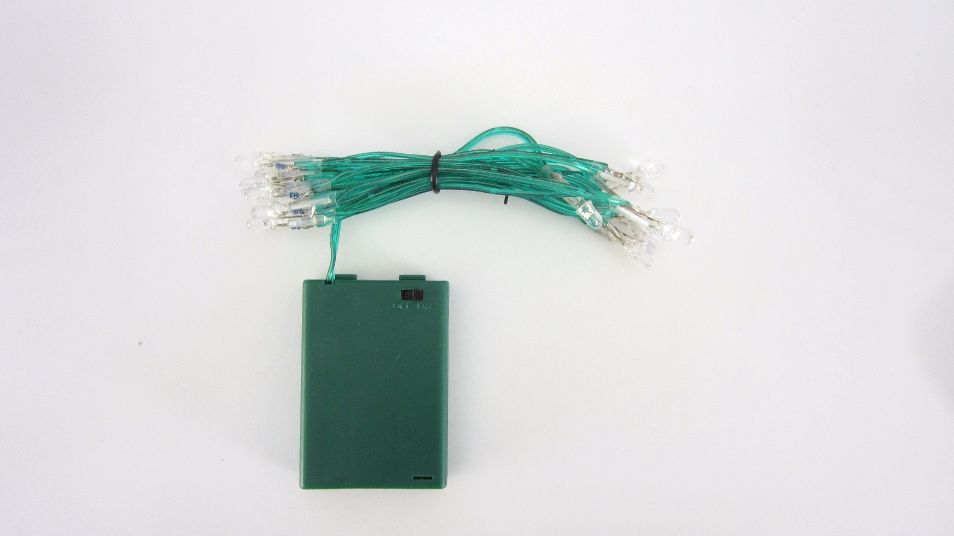
Battery Powered Christmas Lights
Jumper Wires
Laser Pointer
Photoresistor
10 kohm Resistor
Alligator Clips
Tools:
Soldering Iron and Solder
Wire Cutters
Wire Strippers
Screwdriver
Hot Glue Gun and Glue Sticks
How the Sensor Works


To detect when someone scores, I am using a basic light sensing circuit. A laser pointer is set up on one side of the hole. On the other side of the hole, a light detector is positioned in line with the laser pointer.
The light detector that I am using is a photoresistor that is wired in series with a 10 kohm fixed resistor. The 10 kohm resistor is connected to 5V and the photoresistor is connected to GND. The center pin between them is connected to an analog input pin on the arduino. When the light beam of the laser pointer is interrupted by the bag going through the hole, the voltage at the center pin goes up. This change in voltage is detected by the Arduino and the Arduino activates lights and sounds.
Connect the Arduino to the Laser Pointer


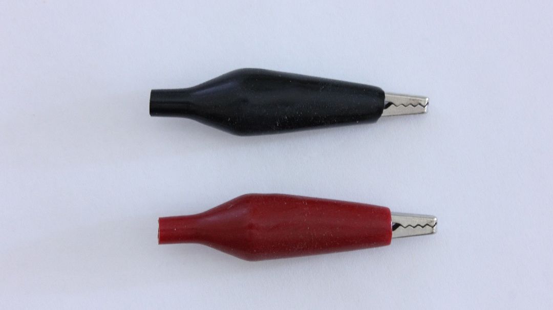


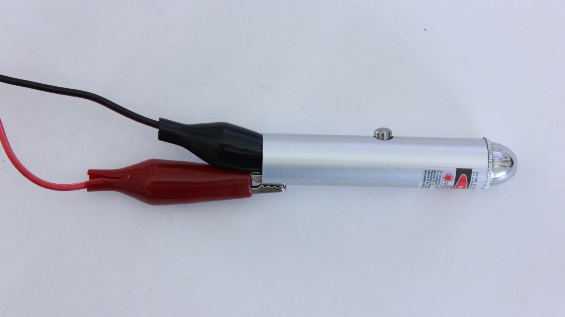

I am powering the laser pointer from the Arduino. To do this, I took a pair of jumper wires and I attached alligator clips on the ends. The negative wire was attached to the spring inside the laser pointer. Then this wire was connected to GND. The positive wire was connected to the barrel of the laser pointer. This wire was then connected to 5V from the Arduino. To keep the laser pointer on, you can just wrap some tape around the barrel over the switch.
Connecting the Sensor to the Arduino


The center pin of the sensor needs to be connected to one of the analog input pins. In this project, I am using the Adafruit wave shield to add sound effects. So I first attached the wave shield to the Arduino. Then I used a jumper wire with a female header pin connector to connect to the top of the wave shield.
Connect the Arduino to the Lights


The lights require more power than Arduino can output. So we need to use an external power source. I decided to use two strings of battery powered LED lights. To turn the lights on and off, I am using a pair of IRF510 power MOSFETs. The gate of the MOSFET is connected to digital pin 6 on the wave shield. The source pin of the MOSFET is connected to the GND pin on the wave shield. The source pin of the MOSFET is also connected to the negative terminal of the light's battery pack. The Drain pin of the MOSFET is connected to the spring of the battery holder. These are separated and insulated from each other by inserting a piece of card stock between them. With this card in place, the light circuit can only be completed through the transistor.
When a HIGH signal is sent from the Arduino to the Gate pin, the transistor connects the battery to the LEDs and the lights turn on.
The Arduino Code

// Here is a copy of the code that I used for this project. You can copy and paste it into a new sketch or download the code file.
#include
#include
SdReader card; // This object holds the information for the card FatVolume vol; // This holds the information for the partition on the card FatReader root; // This holds the information for the filesystem on the card FatReader f; // This holds the information for the file we're play
WaveHC wave; // This is the only wave (audio) object, since we will only play one at a time
#define DEBOUNCE 100 // button debouncer
int ledPin = 6;
// this handy function will return the number of bytes currently free in RAM, great for debugging! int freeRam(void) { extern int __bss_end; extern int *__brkval; int free_memory; if((int)__brkval == 0) { free_memory = ((int)&free_memory) - ((int)&__bss_end); } else { free_memory = ((int)&free_memory) - ((int)__brkval); } return free_memory; }
void sdErrorCheck(void) { if (!card.errorCode()) return; putstring("\n\rSD I/O error: "); Serial.print(card.errorCode(), HEX); putstring(", "); Serial.println(card.errorData(), HEX); while(1); }
//<------------------------------------------------------------------------------ Void Setup void setup() { // set up serial port Serial.begin(9600); putstring_nl("WaveHC with 6 buttons"); putstring("Free RAM: "); // This can help with debugging, running out of RAM is bad Serial.println(freeRam()); // if this is under 150 bytes it may spell trouble! // Set the output pins for the DAC control. This pins are defined in the library pinMode(13, OUTPUT);
// if (!card.init(true)) { //play with 4 MHz spi if 8MHz isn't working for you if (!card.init()) { //play with 8 MHz spi (default faster!) putstring_nl("Card init. failed!"); // Something went wrong, lets print out why sdErrorCheck(); while(1); // then 'halt' - do nothing! } // enable optimize read - some cards may timeout. Disable if you're having problems card.partialBlockRead(true); // Now we will look for a FAT partition! uint8_t part; for (part = 0; part < 5; part++) { // we have up to 5 slots to look in if (vol.init(card, part)) break; // we found one, lets bail } if (part == 5) { // if we ended up not finding one :( putstring_nl("No valid FAT partition!"); sdErrorCheck(); // Something went wrong, lets print out why while(1); // then 'halt' - do nothing! } // Lets tell the user about what we found putstring("Using partition "); Serial.print(part, DEC); putstring(", type is FAT"); Serial.println(vol.fatType(),DEC); // FAT16 or FAT32? // Try to open the root directory if (!root.openRoot(vol)) { putstring_nl("Can't open root dir!"); // Something went wrong, while(1); // then 'halt' - do nothing! } // Whew! We got past the tough parts. putstring_nl("Ready!");
pinMode(ledPin, OUTPUT); }
//<------------------------------------------------------------------------------------- Void Loop
void loop() { //putstring("."); // uncomment this to see if the loop isnt running
int sensorValue = 0; int sensorPin = 5; int sensorThreshold = 200;
sensorValue = analogRead(sensorPin); // read the input pin
Serial.println(sensorValue); // debug value
if(sensorValue > sensorThreshold) { Serial.println("Play Sounds and Lights"); digitalWrite(ledPin, HIGH); // sets the LED on playcomplete("1.WAV"); digitalWrite(ledPin, LOW); // sets the LED off delay(500);
} }
// Plays a full file from beginning to end with no pause. void playcomplete(char *name) { // call our helper to find and play this name playfile(name); while (wave.isplaying) { // do nothing while its playing } // now its done playing }
void playfile(char *name) { // see if the wave object is currently doing something if (wave.isplaying) {// already playing something, so stop it! wave.stop(); // stop it } // look in the root directory and open the file if (!f.open(root, name)) { putstring("Couldn't open file "); Serial.print(name); return; } // OK read the file and turn it into a wave object if (!wave.create(f)) { putstring_nl("Not a valid WAV"); return; } // ok time to play! start playback wave.play(); }
Prototype the Circuit on a Breadboard

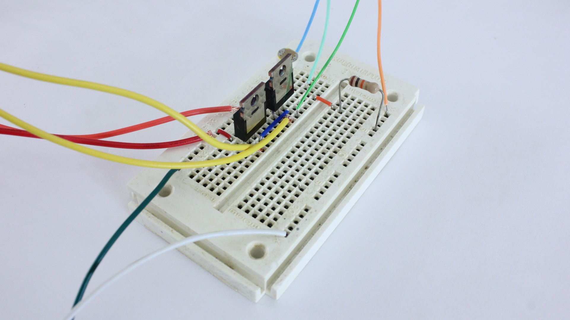


It is always a good idea to prototype a new circuit on a breadboard before soldering it together. This give you a chance to make any necessary changes before everything is soldered in place.
Solder the Circuit Onto a Perf Board
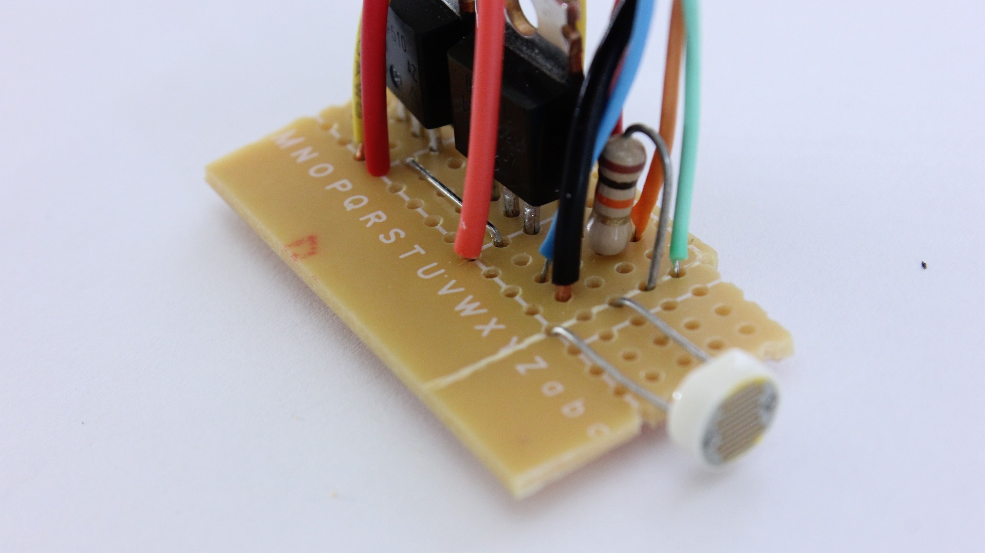


Once everything is working properly, you can solder all the parts onto a printed circuit board or a piece of perf board.
Set Up the Wave Shield


If you want your game to play sounds, you can add a Wave Shield to your Arduino. This will let it play audio files. This shield may be purchased as a kit from Adafruit or fully assembled from the MakerShed. If you choose to assemble it from the kit, you can get detailed instructions from the Adafruit website. For this project, one additional wire needs to be soldered to digital pin 6 to allow it to activate the lights.
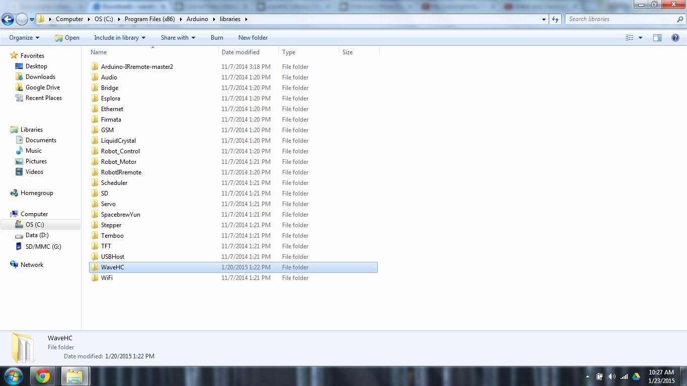
Once you have an assembled wave shield, you need to download the WaveHC library. You can download a copy from the author's website here or you can just download the zip file attached to this step.
Download the zip file. Then unzip/extract the files. Copy the WaveHC folder into the libraries directory of your Arduino program folder. You can find a detailed tutorial on the library and how to use it here.
Downloads
Convert the Audio Files to the .WAV Format

The Wave shield can only play audio files in the .WAV format. So if your sound recorder saves the files in a different format, you will need to convert them to .WAV.
If you have itunes you can use this tutorial to convert them: https://learn.adafruit.com/adafruit-wave-shield-audio-shield-for-arduino/convert-files. You can also use online file converters such as this one: http://audio.online-convert.com/convert-to-wav.
Regardless of which program you use, you need to convert the file to the .wav type. The bit resolution should be set to "16 bit". The sampling rate should be set to 22050 Hz (or 22.050 kHz). The audio channels should be set to "Mono."
For simplicity, I changed my audio file to 1.wav. If you use this file name you will not need to modify the code. Then just load the files onto an SD card and insert it into the wave shield.
Downloads
Attach the Light Sensor Circuit to the Game Board


Now you need to attach the laser pointer and the light sensor to the game board. To do this, I just used hot glue to stick the parts to the under side of the board. Just make sure that the light sensor is perfectly lined up with the beam of the laser pointer.
Attach the Rest of the Parts to the Inside of the Game Board


To secure the rest of the parts just hot glue them to the underside of the board. To help protect the Arduino, I put that inside a plastic project enclosure.
Glue the LEDs in Place


The last thing to do is to glue all the LEDs in place. I used hot glue to mount one string of LEDs around the inside of the hole. Then I mounted the second string of lights around that inside the box.
Test It


Now all you have to do is turn on the power and try it out. Wave your hand in front of the beam. The lights should turn on and the sounds should play.
Use Your Light Up Game Board
.jpg)
.png)
.png)
.png)
Now you are ready to play a game. Whenever you toss a bag into the hole, it will interrupt the beam from the laser pointer. Then the lights and sounds will play. I did this with a basic cornhole board. But you can make this work with lots of different games. For instance you could make this same setup with a basketball goal. Try it out and have fun.