Adjustable 0–40V 0–5A Linear Power Supply (100% Transistor Design – No IC)
by LongTechnical in Circuits > Electronics
144 Views, 2 Favorites, 0 Comments
Adjustable 0–40V 0–5A Linear Power Supply (100% Transistor Design – No IC)

In this project, I want to share a fully adjustable linear bench power supply that I designed and built completely from scratch using only discrete transistors. The PCB for the project was ordered from JLCPCB.
The output can be adjusted from 0 to 40 volt DC, and the current can be limited from 0 to 5 ampere.
Unlike many modern power supply designs that rely on integrated circuits such as op-amps or dedicated voltage regulator ICs, this circuit is built using only basic transistor building blocks. My goal was to keep the design simple in concept, but powerful in performance, so that anyone who studies it can clearly understand how voltage regulation and current limiting work at the component level.
This is not just a power supply — it is also a learning platform for analog electronics.
⚙️ Key Specifications
- Output voltage: 0 – 40V DC adjustable
- Output current: 0 – 5A adjustable limit
- Input: around 30V AC transformer
- Rectified DC voltage: approximately 40V DC
- Fully discrete design (no ICs used)
- Built-in current limiting function
- Suitable for lab and DIY electronics use
Supplies
Electronic Components
- 1 × PCB (Gerber files provided in the end of article)
- 1 × 30 volt AC transformer (minimum 180–300 watt recommended)
- 4 × 10 ampere rectifier diodes
- 1 × 0.1 ohm, 10 watt shunt resistor
- 4 × 0.33 ohm, 5 watt emitter resistors
- 2 × BD137 transistors
- 2 × BD138 transistors
- 4 × TIP142 power transistors (TO-247 package)
- Electrolytic capacitors (50 volt or higher, according to the schematic)
- 0.5 watt Zener diodes (use the exact values shown in the schematic)
- Assorted resistors (according to the schematic)
- Ceramic capacitors
- Electrolytic capacitors
- 1 × 4.7 kiloohm potentiometer
- 1 × 2.2 kiloohm potentiometer
- (or dual-gang 10 kiloohm and 5 kiloohm potentiometers connected in parallel as described in the tutorial)
- Terminal blocks
- Hook-up wire
Mechanical Parts
- Large aluminum heatsink
- Thermal paste
- Screws, nuts, and insulating hardware for mounting the power transistors
- Enclosure (optional)
Tools
- Soldering iron
- Solder wire
- Digital multimeter
- Wire cutter
- Screwdriver
- Bench power supply or AC transformer for testing
- Oscilloscope (optional, for troubleshooting)
PCB Design and Manufacturing
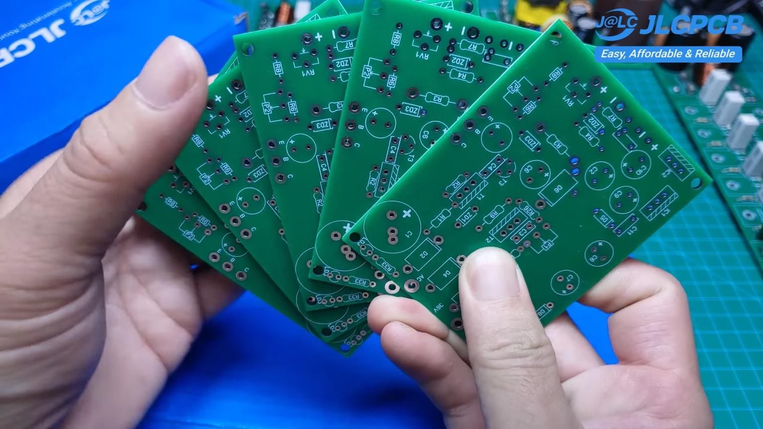
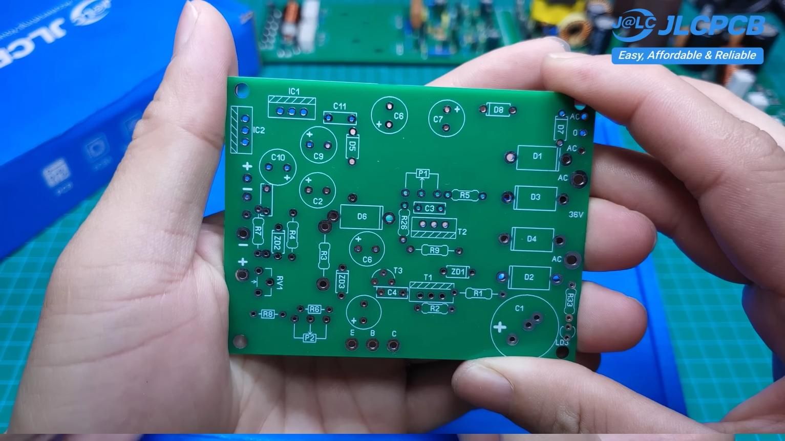
The PCB was designed specifically for DIY builders.
Key goals during layout:
- Easy component placement
- Short high-current paths
- Clear separation between control and power stages
The PCB was manufactured by JLCPCB, and I was impressed by the result:
- Clean solder mask
- Accurate drilling
- Sharp silkscreen printing
The boards arrived in just about one week after uploading the Gerber files.
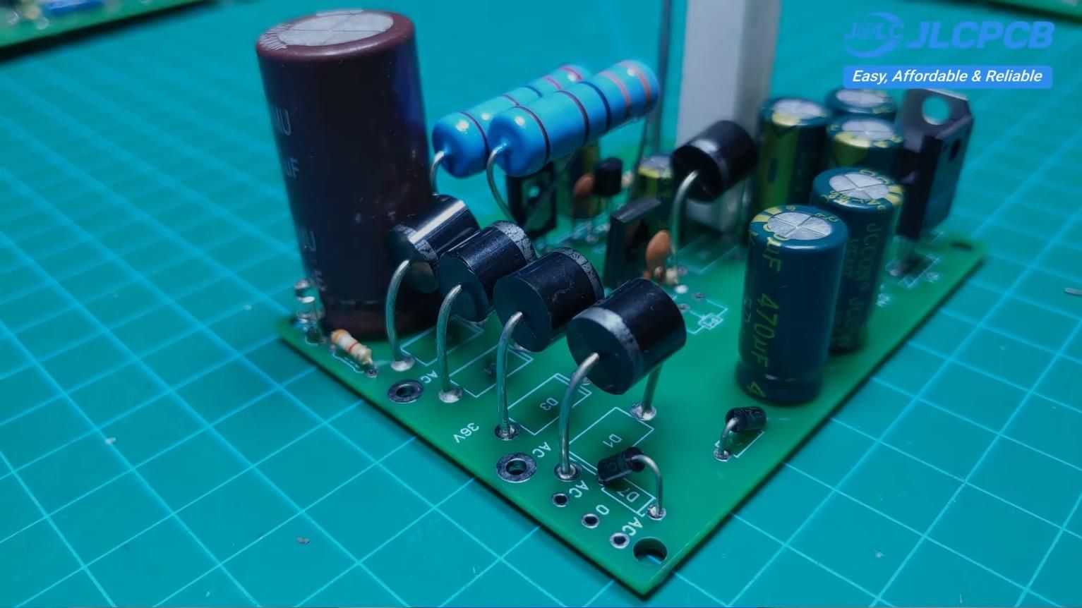
AC Input and Rectifier Stage
1. AC Input and Rectifier Stage
The power source for this circuit is a 30 volt AC transformer.
This AC voltage is first fed into a full bridge rectifier consisting of four 10 ampere diodes. After rectification, the waveform becomes DC, and the voltage rises to approximately 40 volt DC (no load condition).
To smooth this pulsating DC, I use large electrolytic capacitors. These capacitors are critical because they store energy and reduce ripple.
👉 Important note:
The capacitors must be rated at 50 volt or higher, since the no-load voltage can rise above the nominal value.
After rectification, the DC voltage is not perfectly smooth. It still contains ripple depending on load current.
To reduce this ripple:
- Large capacitance is used
- Proper grounding layout is important
- High current paths are kept short and thick
This stage ensures that the control circuit receives a stable reference voltage.
Current Sensing (Shunt Resistor)
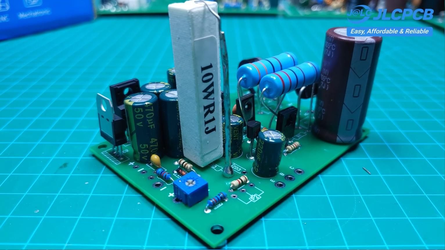
A 0.1 ohm 10 watt resistor is used as a current shunt.
This resistor is placed in the current path and generates a small voltage proportional to the load current.
This voltage is then used by the transistor control network to:
- Detect load current
- Limit current when it exceeds the preset value
This is the heart of the current control system.
Voltage and Current Control (Transistor Network)
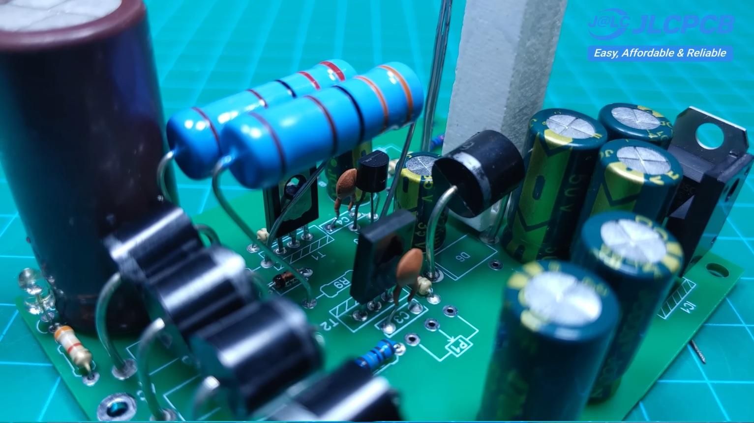
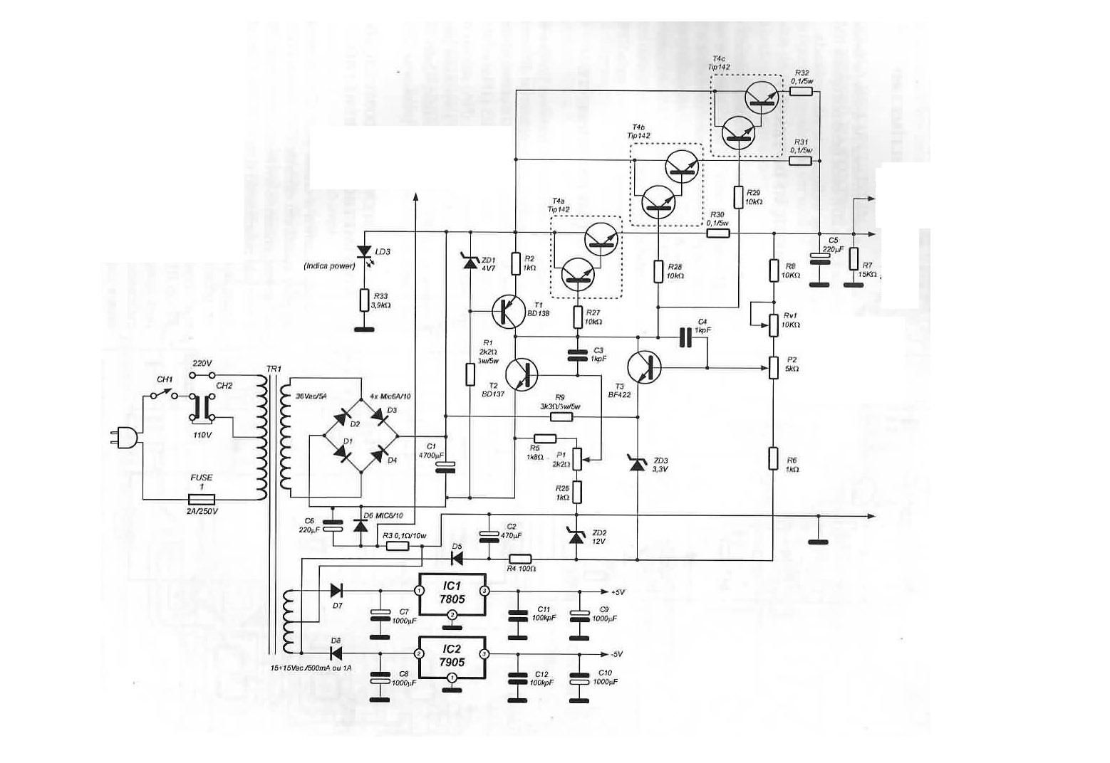
Instead of using op-amps, I designed the control loop using only BD137 and BD138 transistors.
These transistors act as:
- Error amplifiers
- Feedback controllers
- Signal drivers for the power stage
Two adjustable potentiometers are used:
- One controls output voltage
- One controls current limit
The interaction between these two controls allows smooth regulation of both voltage and current.
Power Stage (High Current Output)
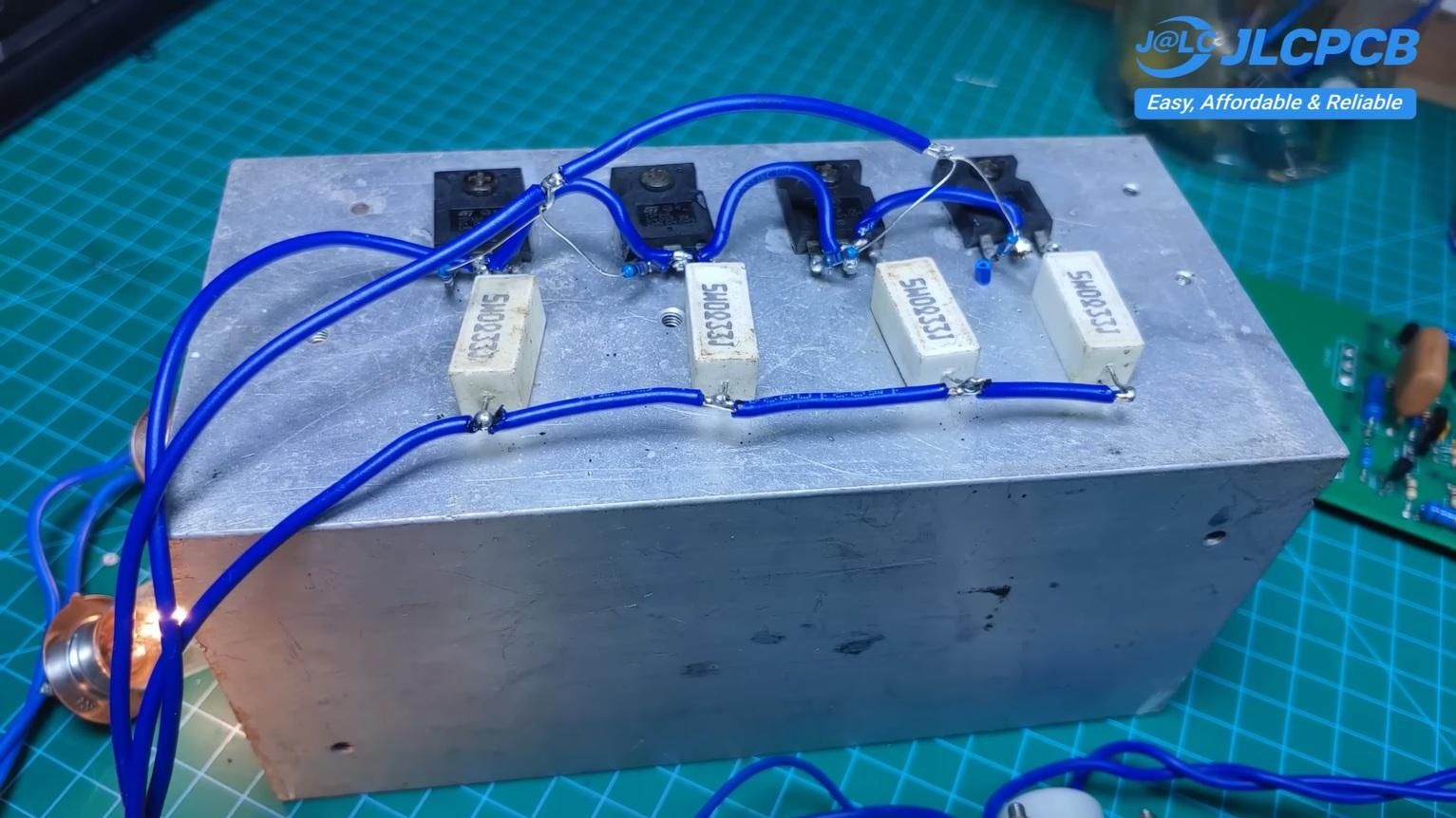
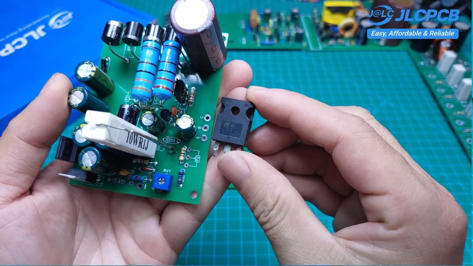
To handle high current up to 5 ampere, the design uses multiple TIP41 / TIP142 transistors in parallel.
Each transistor:
- Shares the load current
- Reduces heat per device
- Improves reliability
To ensure proper current sharing:
- Each emitter is connected through a 0.33 ohm, 5 watt resistor
- All collectors are tied together
- Base resistors (10 kiloohm) stabilize drive current
This configuration prevents thermal runaway and improves stability.
Thermal Design (Very Important)
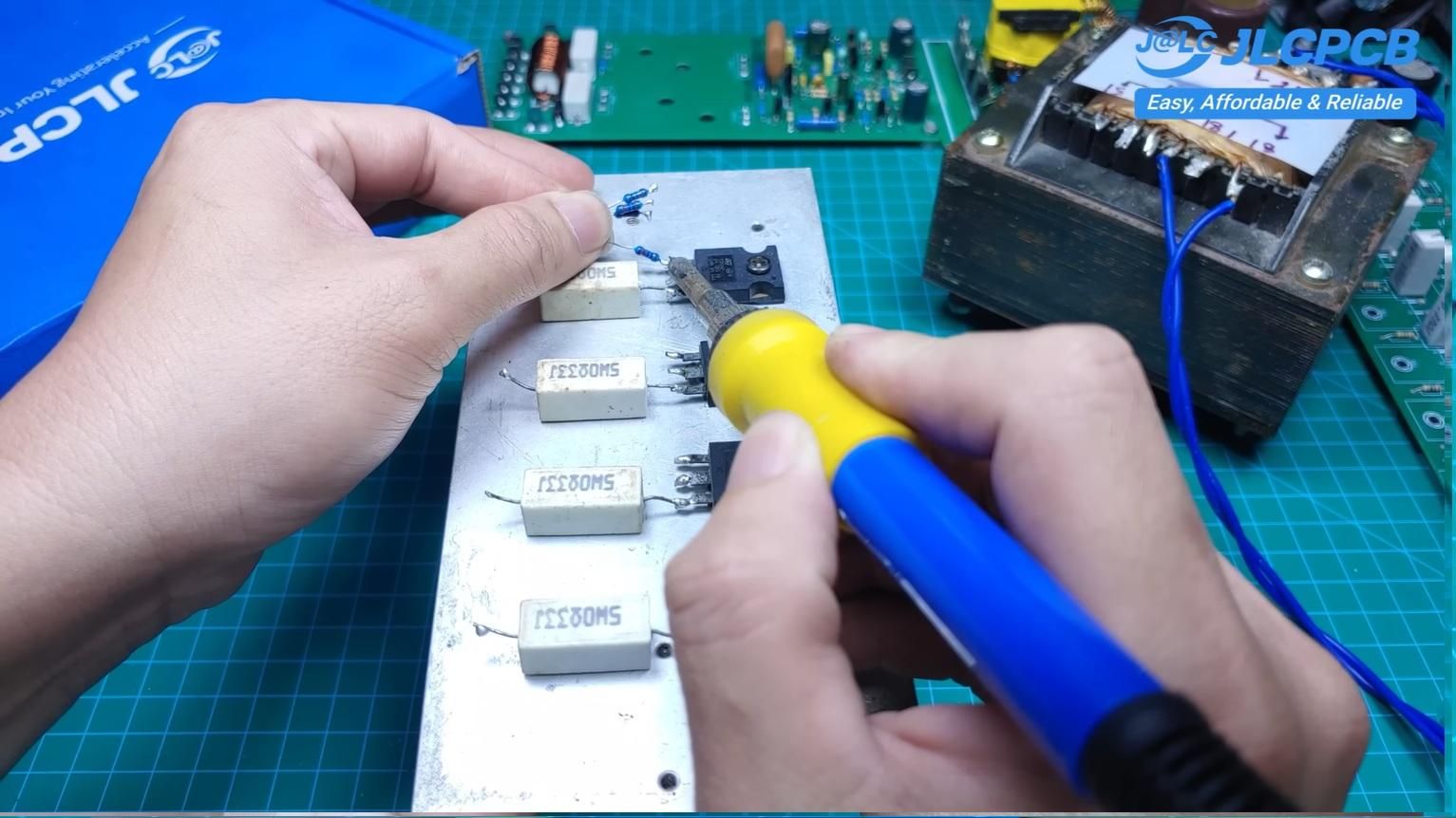
Because this is a linear power supply, heat dissipation is a major concern.
A large heatsink is absolutely required.
Before mounting the transistors:
- Apply a thin layer of thermal paste
- Ensure proper electrical insulation if needed
- Tighten mounting screws evenly
Without proper cooling, the power transistors can overheat and fail quickly.
Zener Reference Network
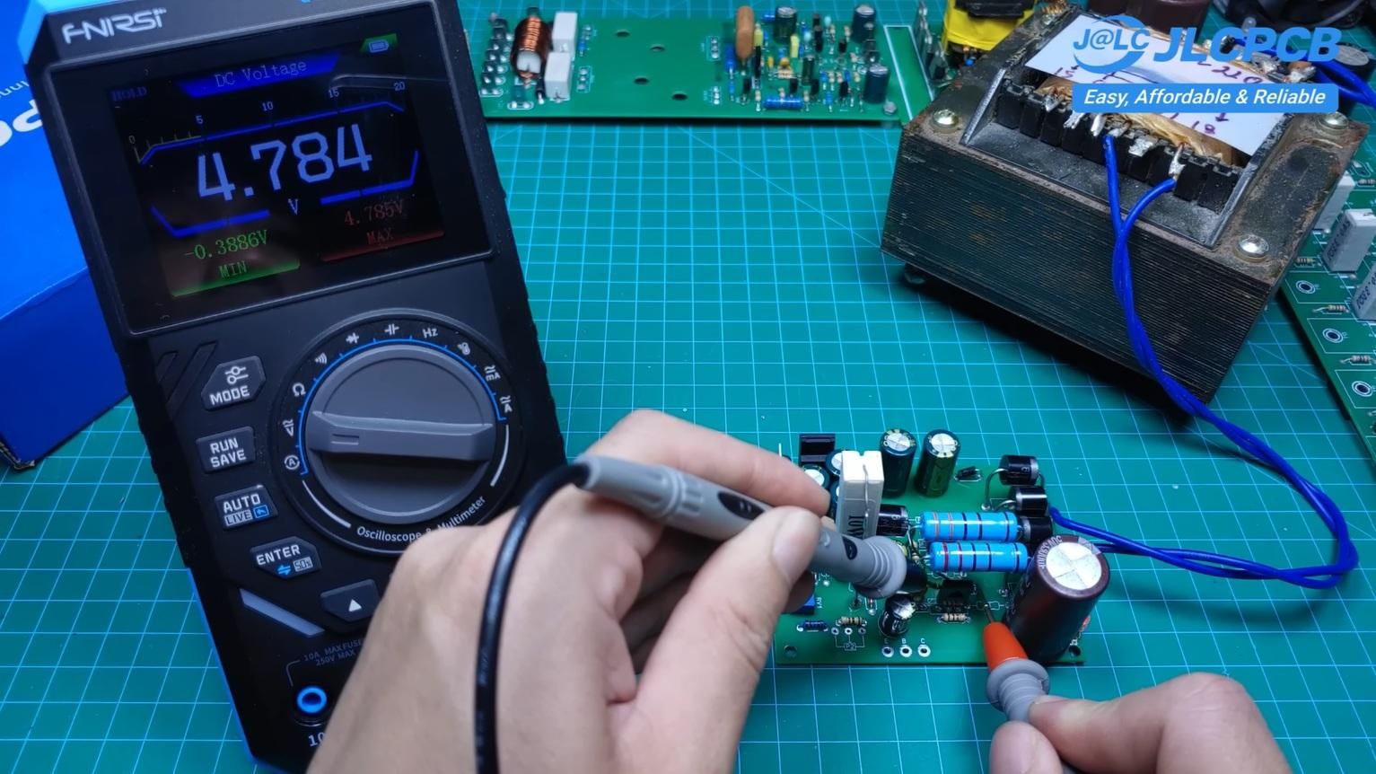
Zener diodes are used to create stable reference voltages.
In this design:
- 0.5 watt Zener diodes are used
- Each Zener must match the schematic value exactly (for example 3.3V, 4.7V, etc.)
Incorrect Zener values will directly affect:
- Output voltage accuracy
- Stability of regulation loop
Testing Setup
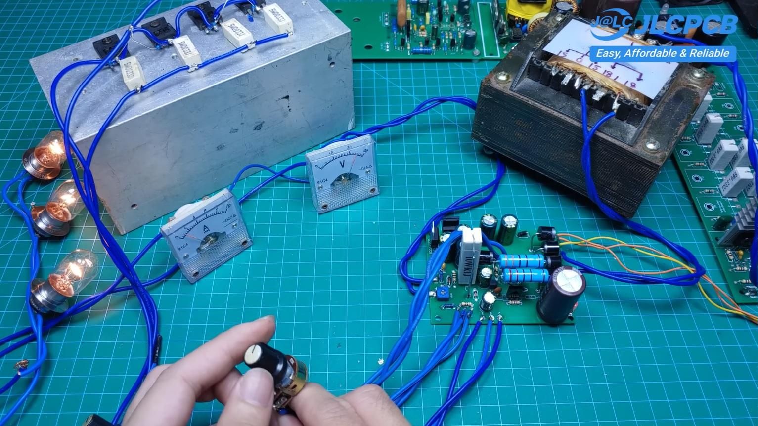
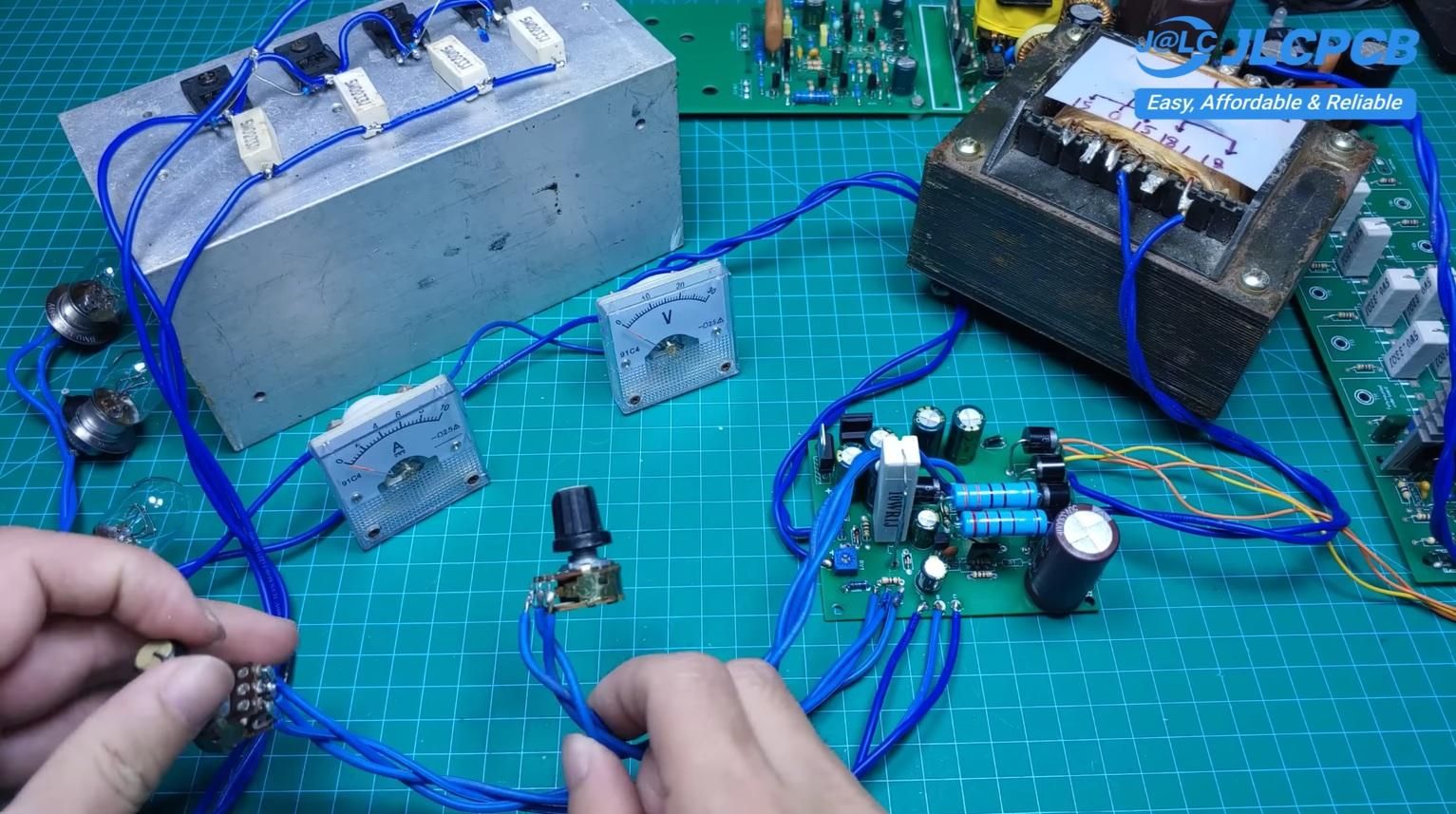
For testing the completed system, I used:
- A 300 watt power supply
- Load: three 12 volt bulbs connected in series (up to 36 volt total load)
- Voltmeter and ammeter to monitor output behavior
This setup allows safe testing of both voltage and current control without risking sensitive electronics.
Important Notes
- Always check rectified DC voltage before connecting the control stage
- Use correct polarity for all Zener diodes
- Ensure proper heatsinking for all power transistors
- Double-check current shunt resistor wiring
- Do not operate without load or proper cooling for long periods
Final Thoughts
This project demonstrates that even without modern integrated circuits, it is still possible to build a fully functional and adjustable power supply using only classic transistor techniques.
More importantly, it helps you understand:
- How voltage regulation really works
- How current limiting is implemented in analog circuits
- How power transistors share load and heat
I hope this project helps you learn and inspires you to design your own analog power systems.
If you have any questions or improvements, feel free to discuss — I’m always happy to share and learn together.