Alarm Clock Featuring Gen4-uLCD-43DT
by 4D Makers in Circuits > Arduino
2498 Views, 20 Favorites, 0 Comments
Alarm Clock Featuring Gen4-uLCD-43DT
4D Alarm Clock project is based on the concept of a simple digitakl alarm clock. It has a real time clock (RTC) which keeps the time updated. Time (24 Hour Format) and day are displayed in the uLCD. It has the menu for the Alarm Settings where you specify the time you want to set the alarm. This also enable the users to use their favourite music as an alarm tone. Volume can be adjusted from 0 to 30. It has Snooze and Wake up button. Snooze can be only used up to three times, after that, the alarm will be deactivated.
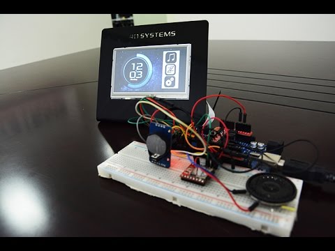
4D Alarm Clock uses gen4-uLCD-43DT as the main display, Arduino Mega Board as a host ,and SOMO-II to store mp3 and wav files to be used as an alarm tone.
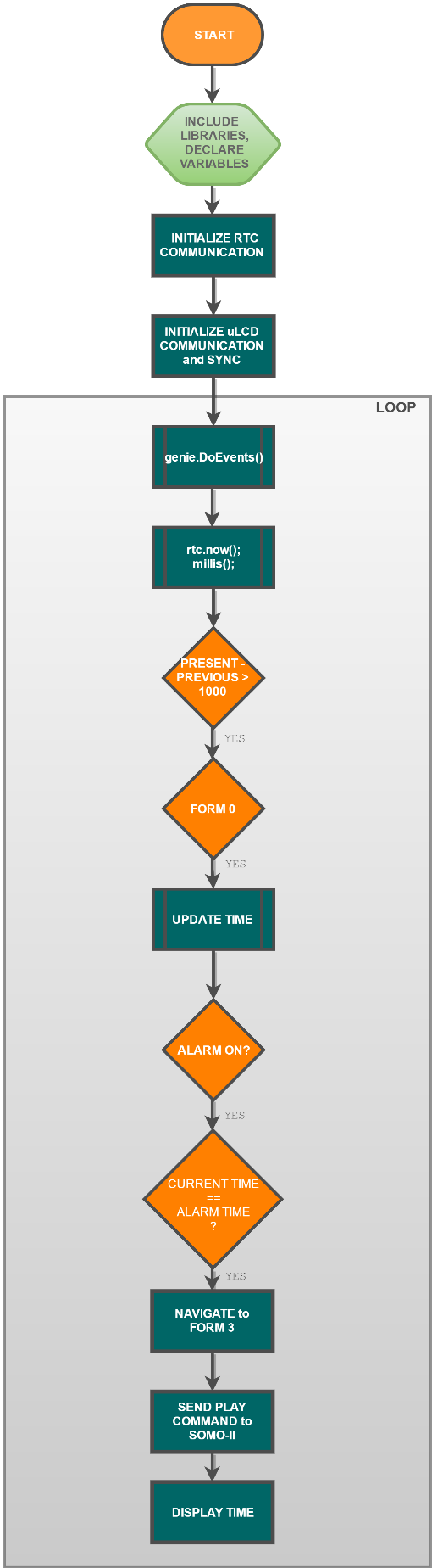
How It Works

Build

Build the project by connecting the components as shown in the diagram above
Components
- gen4-uLCD-43DT
- Arduino Mega
- 4D Arduino Adaptor Shield
- RTC Module
- SOMO-II
- Speake
- r5-way Cable
- gen4 Interface-Board
- Micro USB Cable (for gen4)
- USB Cable to program the Arduino
- Breadboard
- Connecting Wires
Clarification about the components:
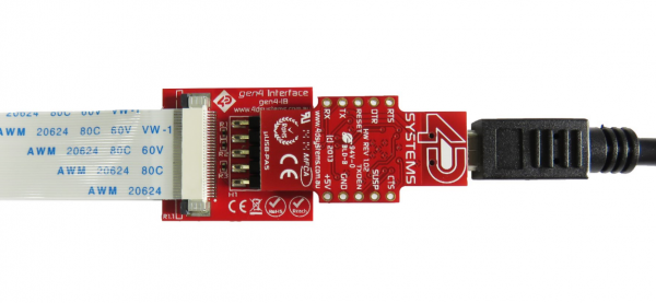
- Use gen4-interface board and uUSB PA-5 to connect the display to the PC as shown in the second figure
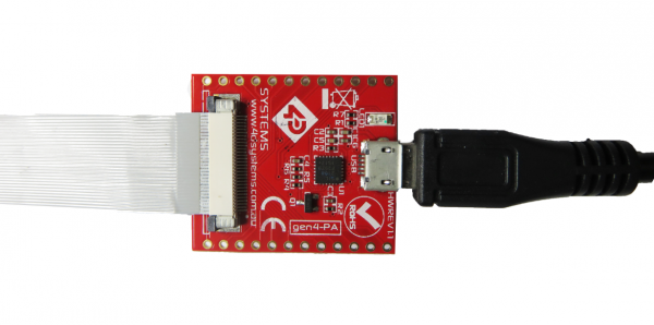
- Or if you have gen4-PA board, connect the display to the PC as shown in the image below. You can also use the gen4-PA board if you want to use its GPIO pins. Shown on the third figure
Program

- Download the project code here.
- Open the project using Workshop 4. This project uses the Visi-Genie Environment.
- You can modify the properties of each widget.
- Connect the display to the PC using uUSB-PA5 and a mini USB cable. Make sure that you are connected to the right port. Red Button indicates that the device is not connected, Blue Button indicates that the device is connected to the right port.
- Now click on the “(Build) Copy/Load” button.
- Workshop 4 will prompt you to select a drive to copy the image files to a uSD Card. After selecting the correct drive, click OK.
- The module will prompt you to insert the uSD card.
- Properly unmount the uSD Card from the PC and insert it to the uSD Card slot of the display module. The image above must appear on your display after completing the steps.
Upload Arduino Sketch
- Open the Arduino Sketch with Arduino IDE.
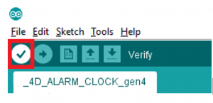
- Click the Verify button to compile the sketch and check if there are no errors.
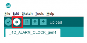
- Then, click the Upload button to load the sketch into your Arduino board. Make sure that you selected the corresponding board and you are connected to the right port.
- After this, you can now test and use your 4D Alarm Clock.
Demo


- Once the project has been set up, and the programs has been uploaded, the time and day must appear on the uLCD Display. The time is updated based on the system you are using (e.g. pc)
- Press on the “Settings Button” to navigate to form 1 where you can set the time you wanted by using the sliders. The Alarm time will be displayed by the LED Digits. Then press the “Alarm Button” to go back to the original form.
- Press the “Music Button” to navigate to form 2 where you can set the sound or audio file you want to use by using the buttons provided on that form. The volume can be also adjusted using the slider. Then press the big “Note button” at the top.
- Press the “Alarm Button” on form 0 to activate the alarm
- Once the alarm is activated, the system will wait for it and will play the music or audio you chose. The project will also show form 3 for the Snooze/Wake up option. You can use Snooze up to three times. It will add five more minutes to the Alarm time. After three consecutive snoozes, your alarm clock will be deactivated and will turn to form 0 again. “Wake Up Button” deactivates the alarm and will bring you back to form 0.
Appendix : Flow Chart