Ambi-8 and Ambi-12
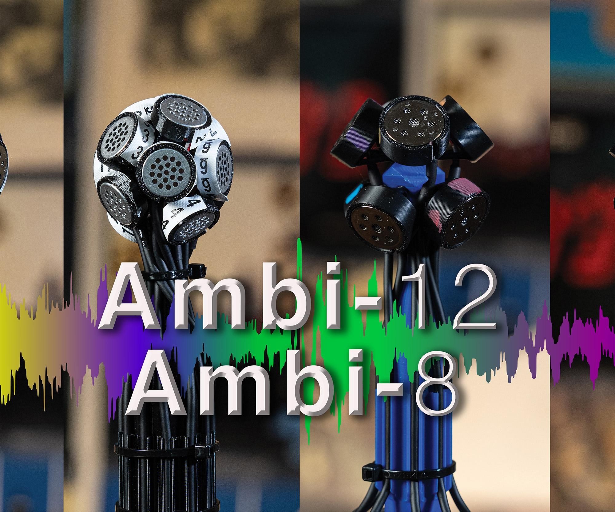
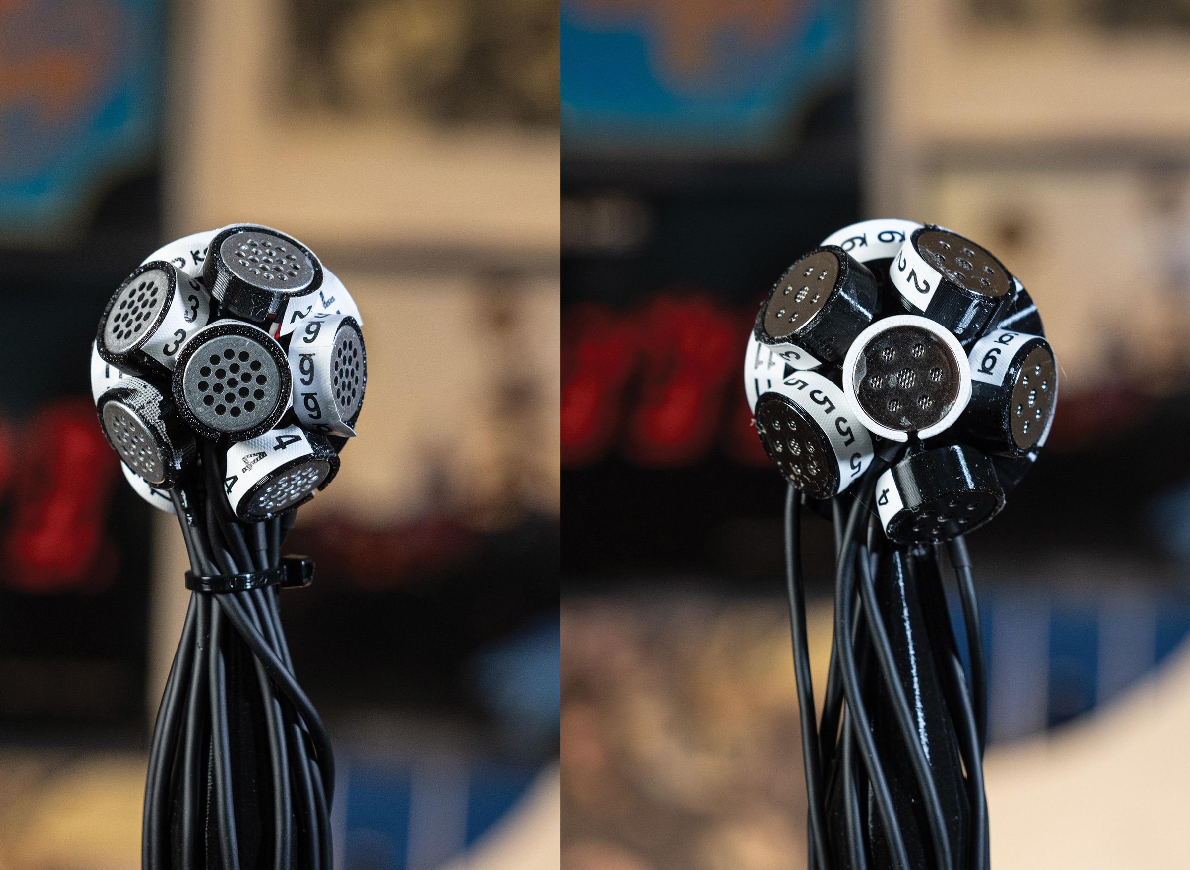
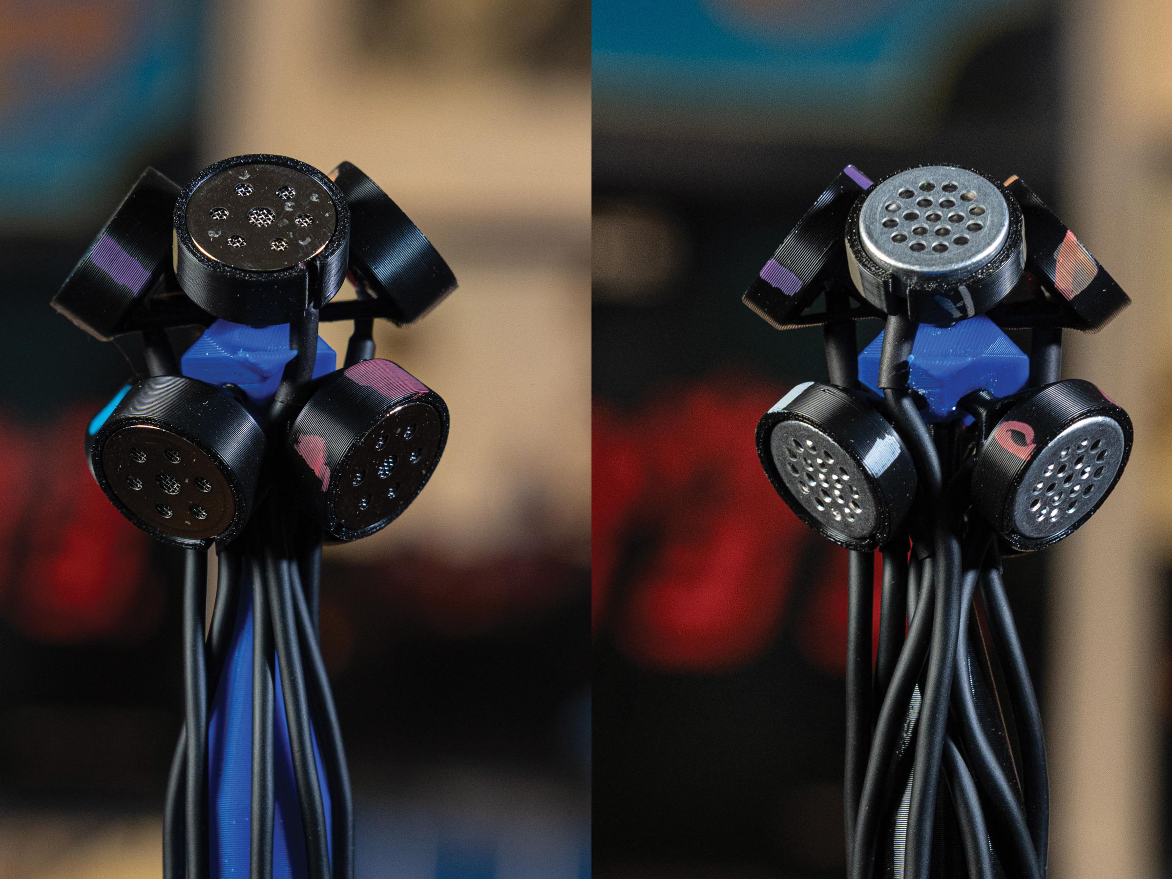
My first instructable for a first order ambisonic microphone was the AmbiAlice, it uses four capsules placed in a tetrahedral arrangement. This is the classic first order ambisonic microphone. And the AmbiAlice is a great one. When I built my immersive 7.1.4 speaker setup I finally heard how good it actually was. With that said, after I went back and listened to some of my older recordings with it mapped out to 7.1.4, I knew there was room for improvement. The spatial resolution was not quite where I wanted it to be. So, I did some research, went back to the drawing board, and came up with Ambi-8 and Ambi-12.
As their names suggest, the number is the number of capsules that each mic contains. Eight and twelve. Along with additional capsules for increased spatial acuity, there were a few other improvements I wanted to make.
- Easier to build
- Easier to 3D print
- Improved cable management
Supplies
Parts List:
- Base (3D Printed) (1)
- Geometry Part (3d Printed) (1)
- Capsule Holders (3D Printed – See Text) (8 or 12))
- Mogami Miniature Microphone Cable W2697 (8-10 ft sections) see text https://www.redco.com/Mogami-W2697.html
- 100K 1/4W metal film resistors (8 or 12) (see text) https://www.digikey.com/en/products/detail/yageo/MFR-25FTF52-100K/9140476
- 158K 1/4W metal film resistors (8 or 12) (see text) https://www.digikey.com/en/products/detail/yageo/MFR-25FBF52-158K/13512
- 3.3uF capacitors (8 or 12) https://www.digikey.com/en/products/detail/panasonic-industry/EEU-EB1J3R3S/949745
- Male XLR Connector (8 or 12) https://www.redco.com/Neutrik-NC3MXX-B.html
- XLR color coded boots (8 or 12) see text https://www.redco.com/Neutrik-BXX.html
- ¼-20 Brass insert https://www.amazon.com/40pcs-Threaded-Inserts-Printing-Components/dp/B0CZPD55C1/?th=1
- Tie wraps.
- Wire Numbers (If you are building the 12 capsule version, these are a must) https://www.amazon.com/Wire-Marker-Klein-Tools-56250/dp/B072SVZKQ5/?th=1
- 16mm JLI Mic Capsules 8 or 12 (See Text) https://www.jlielectronics.com/microphone-capsules/jli-160a11uc680/
- 14mm Primo EM415 Capsules 8 or 12 (See Text) https://www.digikey.com/en/products/detail/primo-company-limited/EM415N/25873214?s=N4IgTCBcDaIA4CcCWBbA9gAgKIFkAsAjAKwgC6AvkA
Review of Ambisonics
Let’s review Ambisonics and how all this works. For me the easiest way to think of ambisonics is Mid Side Stereo on steroids. You have one microphone, the “Mid” which faces front and captures all the sound in front or in the "Middle". Then there is a figure 8 microphone that faces to the side. By combining these via “matrix math” we can derive stereo from them: “left” = “mid + side”; “right” = “mid − side” (using a polarity-reversed version of the side signal). When the MS mic is recorded we have two channels of audio but they are not stereo until we decode them. Think of the raw audio being “A” format Mid Side. First order Ambisonics extends this into 3 dimensions. It works the same way except with four signals.
If we replace the “Mid” with an omni signal called “W” and create “X”, "Y” and “Z” signals that are the figure 8’s for front/back, left/right, and up/down we now have First Order Ambisonics (FOA). This was invented in the 1970’s and you can learn more about it here. There is a fantastic open source book on Ambisonics here. My first ambisonic mic, the AmbiAlice uses the classic tetrahedral array. When recording with it we captured the raw audio from the capsules and then had to convert it to WXYZ format, called B format. The original or raw audio is called A format. This is our first point of potential confusion. When recording you need to keep track of the four capsule positions. Then when encoding into B format there are a couple of standards for the channel order after encoding. I labeled the native B format above as WXYZ. It is a four channel audio file. The WXYZ part means the W is channel 1, X channel 2, Y channel 3, and Z is channel 4. That is how this was originally done. It was named FuMa for Furse-Malham. The original FuMa convention worked well for first-order Ambisonics. Modern Ambisonics generally uses ACN or Ambisonic Channel Number because it provides a simple mathematical numbering system that extends unambiguously to second, third, and higher orders. ACN is commonly paired with SN3D normalization, forming the modern AmbiX convention. Confused yet? Don't worry, we just have to remember which one to select in our encoder and then when decoding it. Multiple people gotten their PhD thesis over this, including a good friend of mine. The original Ambisonic/B-format idea was conceived back in the 1970s, mainly through Gerzon and colleagues. The Furse-Malham extension to second/third-order B-format was conceived/developed in the late 1990s but I am not sure anyone used it until the early 2000's. In 2002 Jens Meyer and Gary Elko published a paper describing a 32 capsule microphone, then built it, started MH acoustics and sell it as the EigenMike
FuMa = WXYZ | RSTUV | KLMNOPQ ande ACN = WYZX | VTRSU | QOMKLNP
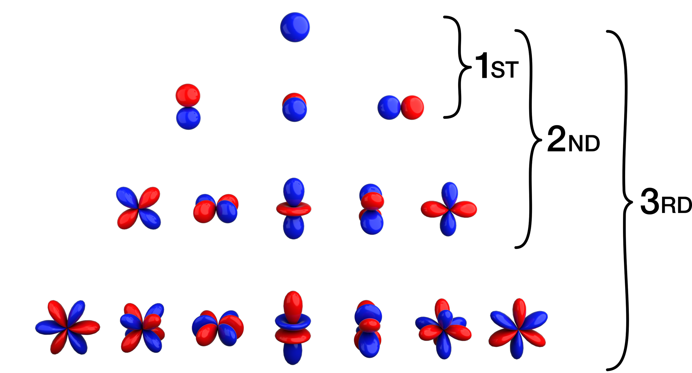
So what are the “VTRSU” and other letters? Yikes! They are Spherical Harmonics. Ambisonics represents sound as a combination of spherical harmonic patterns. Each pattern describes a different kind of directionality. The lowest-order pattern is an omni pattern, which captures sound equally from all directions. The next patterns are figure-8 shapes pointing front-back, left-right, and up-down. Higher-order patterns add more complex shapes, allowing the sound field to be described with more spatial detail. They are the building blocks we are using to describe a 3D sound field. And the best part is your DAW and some open source plugins do all the complex math we need to make this work. Things like Legendre Differential Equations. Even more fun: Jacobians and something called the Frobenius norm… Yea, I’m going to let the plugin do that…
When we go into higher order ambisonics, we need more channels. As we go up in order the number of signals or channels N = (ambisonic order +1)2 . 1st order is 4, 2nd order is 9 and 3rd order is 16.
The bottom line here is this: There are two formats we need to worry about: “A” format and “B” format. A format is what we are recording directly out of the microphone, and “B” format is after it is converted into the Spherical Harmonics. Think of it as A format is what all the microphones heard, B format is the sound field that most likely produced it. For A format, we need to keep track of the capsules positions in terms of where they are pointing horizontally and vertically using Azimuth and Elevation coordinates. And then when in B format, the channel order. We do that by making sure we select the right one on the plugin. Usually ACN and one last parameter we haven't talked about yet, channel normalization. We use SN3D which stands for Schmidt semi-normalisation and is commonly used in geology and magnetics. Basically it normalizes all the signals so that we don't exceed a maximum output when the Spherical Harmonics are decoded into speaker or headphone outputs. All you have to do is select ACN and SN3D in the plugin. We will go into more detail when we encode and decode the mics we are about to build.
A final key point here is that there is a difference between the number of capsules in use and the number of spherical harmonics used. They are not the same thing. There is also a big difference between Ambisonics as a method for working with immersive audio, and as a method for capturing immersive audio.
After I published the AmbiAlice I found another ambisonic mic project called the SpHEAR https://cm-gitlab.stanford.edu/ambisonics/SpHEAR they explore an 8 capsule and propose a 12 and 20. I got some great ideas from this and they were inspirational to the Ambi-8 and Ambi-12. They showed a geometric shape with holes in the faces for capsule holders to press into. Kind of like a tinker toy except the shapes looked like dice used in Dungeons and Dragons.
The Builds
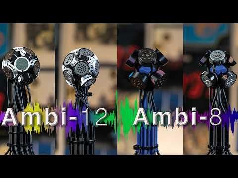
OK, let's look at the builds here. They are very similar. Let's start with the mechanical side of things, the 3D printed parts. Each mic has three sections to it. First the geometry. We need a means of pointing the capsules in the right direction, so I designed a dodecahedron for the 12 capsule mic with a small hole in each of the faces plus one centered on an edge for mounting. Then for the 8 capsule version I designed a four sided pyramid shape that had faces angled up at 45° and added holes on each face. I duplicated that, flipped it over and rotated it 45°. That gives us four capsules facing up and four facing down with a capsule every 45° if you are looking down from above. Finally I added a hole to mount it on and a protruding piece so I could know where it was pointing. Without the capsules in it, it looks like a duck head. If the +/-45° sounds different than commercial mics - it is. We will address that later.
The base is a cylinder that then tapers up to a pin that the geometry shape presses into. The press isn't tight as we will use glue during assembly. On the outside of the cylinder there are evenly spaced wire clips that the capsule wiring presses into. This solved my cable management issue. It is also one of the main challenges of other higher order ambisonic microphones - cabling. The commercial mics I know of use LEMO connectors https://www.lemo.com/en that breakout into XLR cables. For commercial products that makes a lot of sense but also adds costs that I would like to avoid. The EigenMike uses Dante or Madi which maked sense for 32 or 64 channels but puts it even further away from ease of use. In our build we are going to directly wire the capsules to the XLR connectors with some electronics in them. We will form a neat bundle as we go. The final part of the base is a hole where we can insert a ¼-20 brass thread adapter. That is how we will mount them.
The one final piece is the capsule holder. I designed two of these to allow you to use one of two capsules, the JLI16mm one with built in FET, or a Primo EM415. The JLI one is identical to the one used in my 3DORTF array. There are sleeves with the same inner diameter as the capsule with a slit in them to allow for both a bit of expansion and to slide the wire through when inserting the capsule. The JLI one is 16mm in diameter and 7mm deep. The Primo is 14.6mm in diameter and 4.6mm deep. Then they have four arms that meet at a pin that presses into the geometry piece. The pin has a slit in it to allow it to flex when inserted. We will apply a little glue to ensure they stay in place.
3D Printing
All the parts print easily. That is the beauty of this design. The base prints facing up with the wire holders angles so there is no need for supports. The same goes for the capsule holders. The geometry shapes have holes for all the capsule holders. The 8 capsule holder prints best when the direction indicator faces up @45 degrees. See the photos. The dodecahedron for the 12 capsule version prints best when the hole on the face for the base is adjacent to the face lying on the print bed.
There are two sizes of capsule holders depending on which capsule you are using. I built one of each of these with the JLI 16mm and the Primo 14mm. Spec wise they are very similar. I used the JLI ones in Maurice and other projects and know them really well. The Primo’s are a new version of one they have discontinued but had a really good reputation. They are also used in one of the commercial Ambisonic microphones out there. I plan on measuring both (working on this one...). You can a side by side comparison with downloadable audio to so you can listen and judge for yourself.
The Electronics: the Simple P48
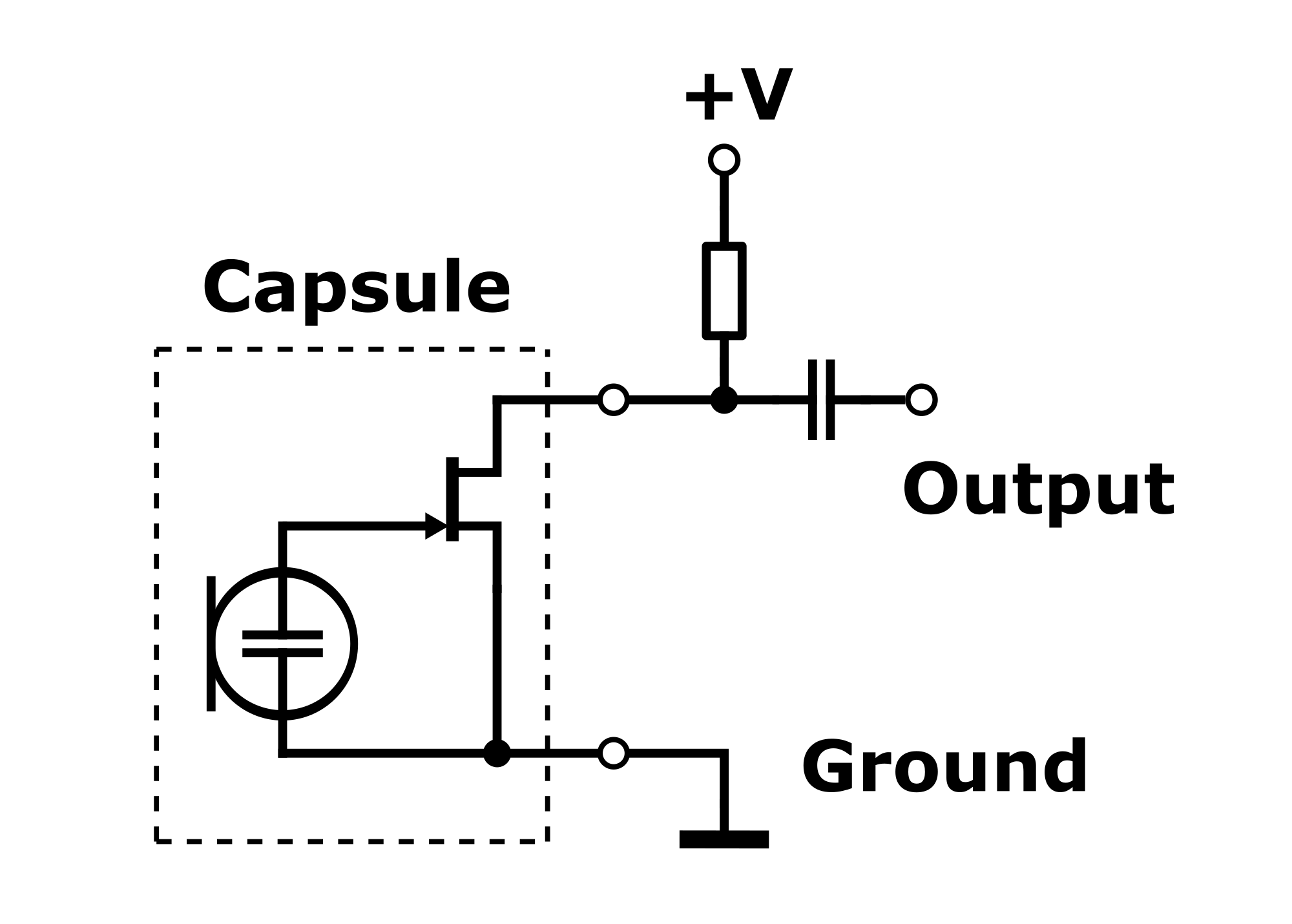
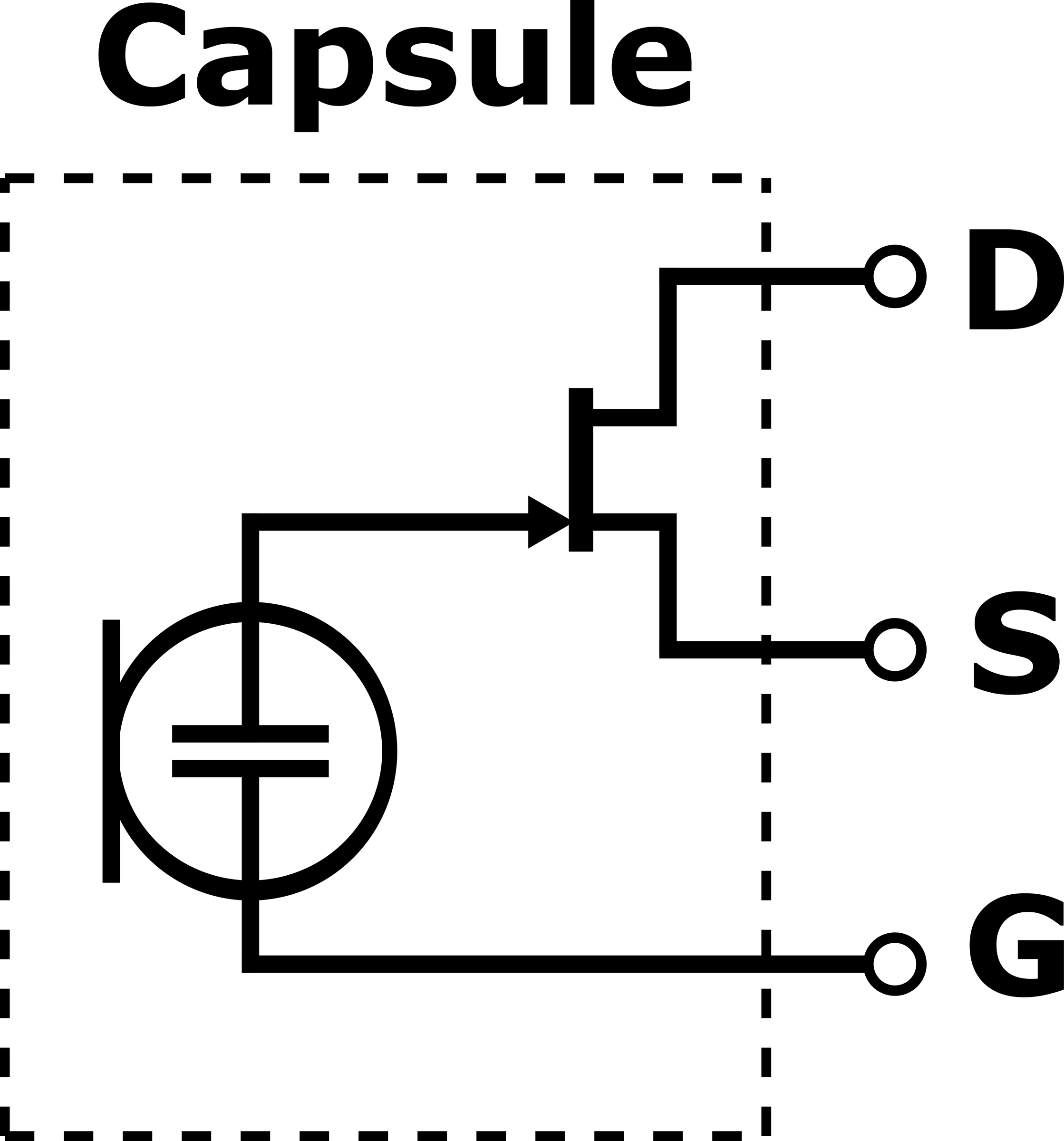
The capsules have a built in FET. That means we can use the simple P48 circuit. This is my favorite way of connecting an electret capsule to a Mic Preamp or recorder. I have described it in other Instructables but a quick review is in order.
Normally we use PIP power with electret capsules that have a FET in them.
Plug-In Power (PIP)
Typically:
- 5 V
- 2.2 kΩ resistor
- AC coupling capacitor
Recorders and sound cards provide this internally on 3.5 mm inputs. All we need to do is connect them to a connector and plug them in. The fet draws enough current to bias itself to about half of the incoming 5 volts. Then when sound comes it the conduction changes and we see our audio signal across it. That gets coupled through the capacitor into the recorder or sound card. The resistor and capacitor are already inside the device we are plugging into so we never see them. If we make the five volts larger we can still get this to work but the 2.2 KΩ resistor has to get larger as well. Which, in a nutshell, brings us to the Simple P48.
The Simple P48
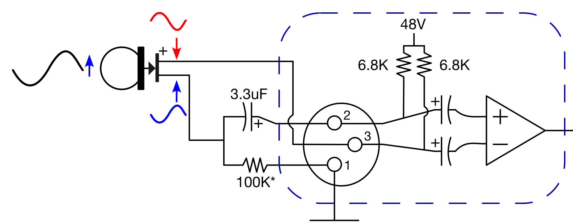
You can power an electret capsule from phantom power using just two components. The trick is leveraging the internal 6.8 kΩ resistors in the preamp. The capsule forms a divider with the 6.8 kΩ on Pin 3 and an external resistor. The resistor value depends on the capsule. The JLI16mm Capsule uses 158K and the EM415 uses 100K.
When sound pressure increases:
- Capsule conducts more
- Voltage across capsule drops
- Voltage across Pin 3 increases
- Voltage across Pin 2 decreases
The capsule body floats meaning it is not connected to ground. It can't be or the circuit won’t work. It must be insulated. The capsule holders we are using take care of this for us.
Is this balanced? Yes.
There is a small impedance difference between legs. You may see about 0.6 dB level difference between pins with a slight variation in impedance as well. Not enough to cause issues. This circuit easily works with 100ft cable runs with no issues. Along with working really well, it is… “simple”.
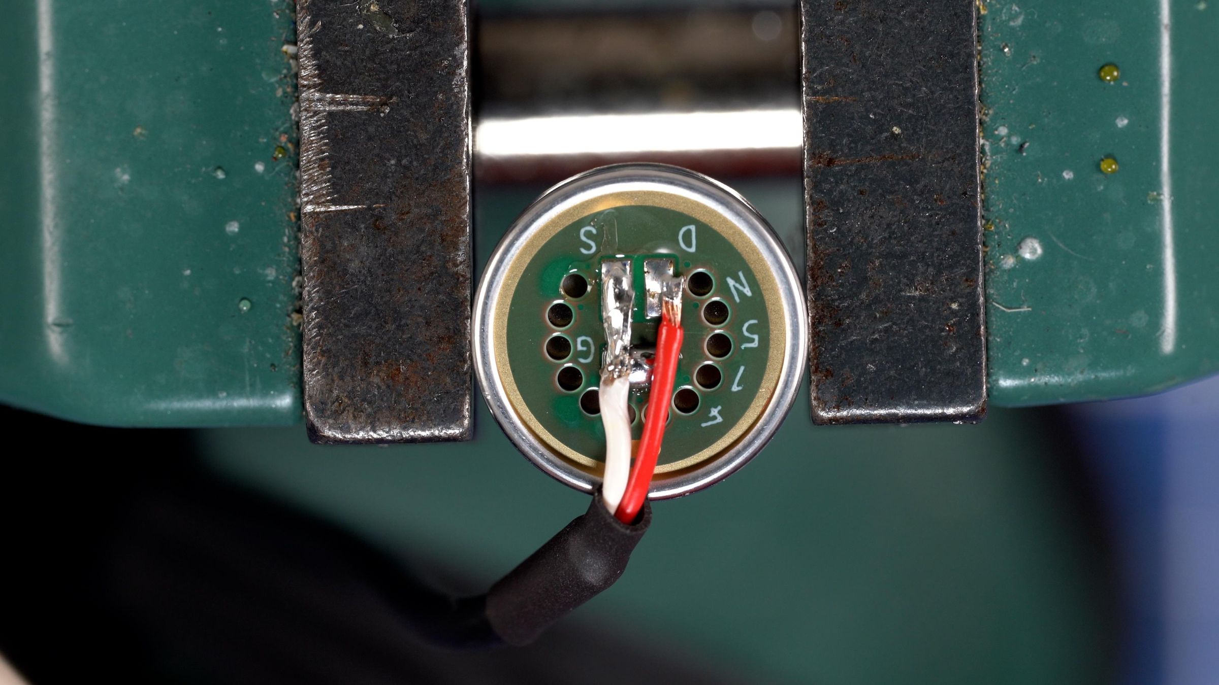
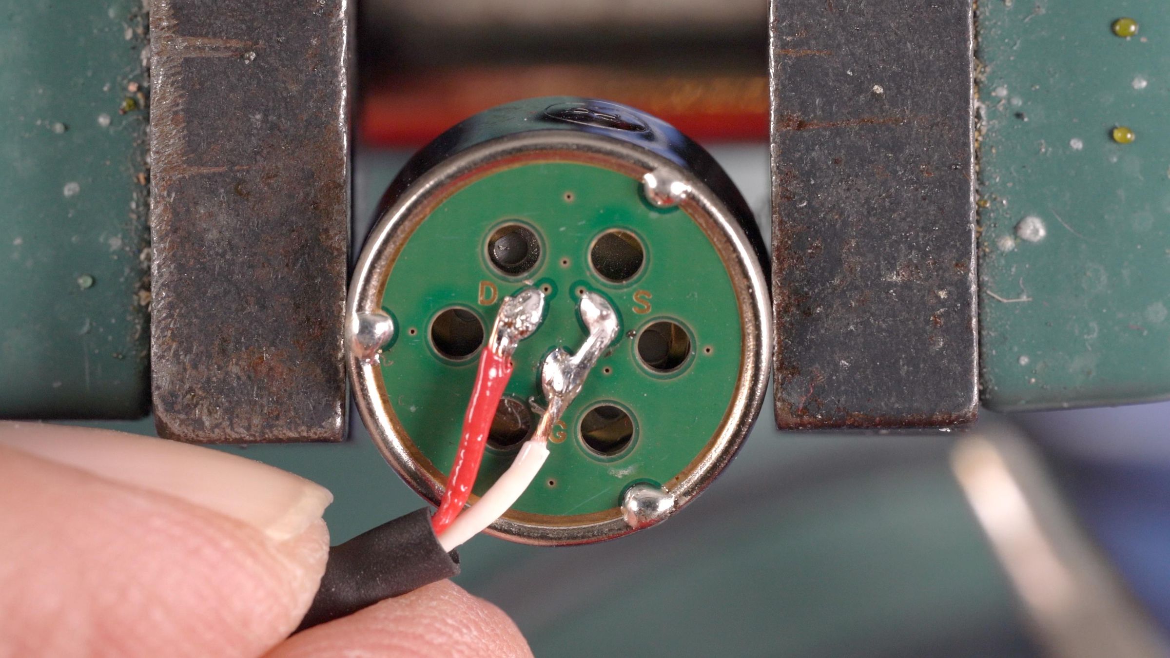
There is one more wiring thing we need to do here. The capsules we are using are “three terminal”. Meaning that the Source (S) and Drain (D) terminals are brought out separately. We are going to tie the Source to Ground and make the capsule into a two terminal capsule.
Building
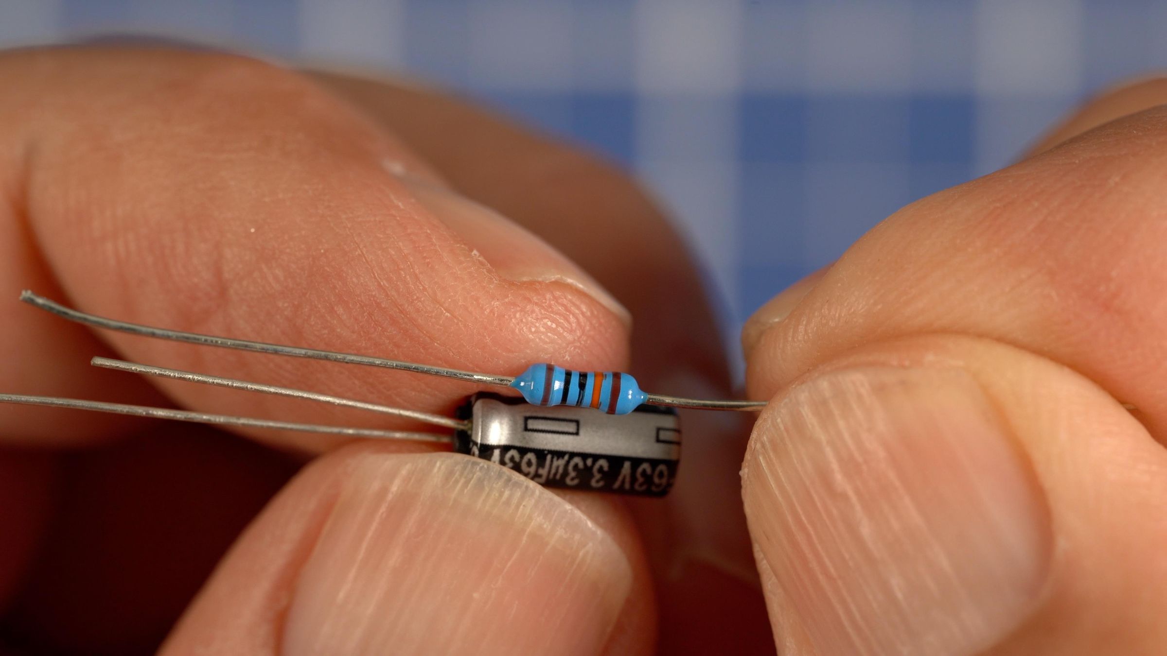
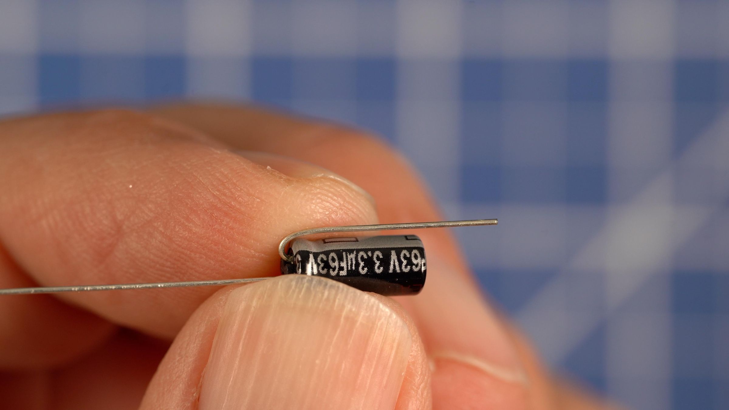
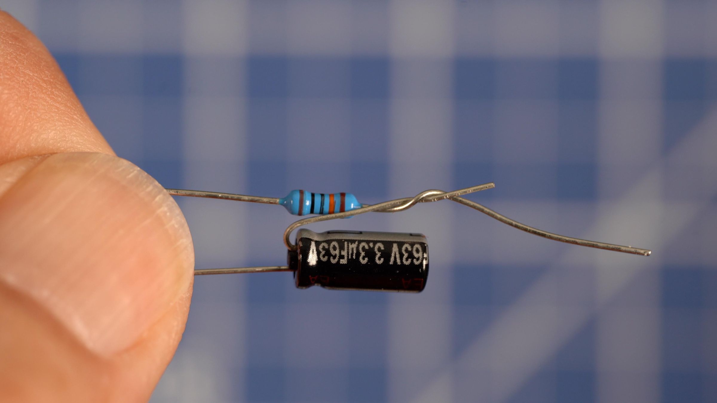
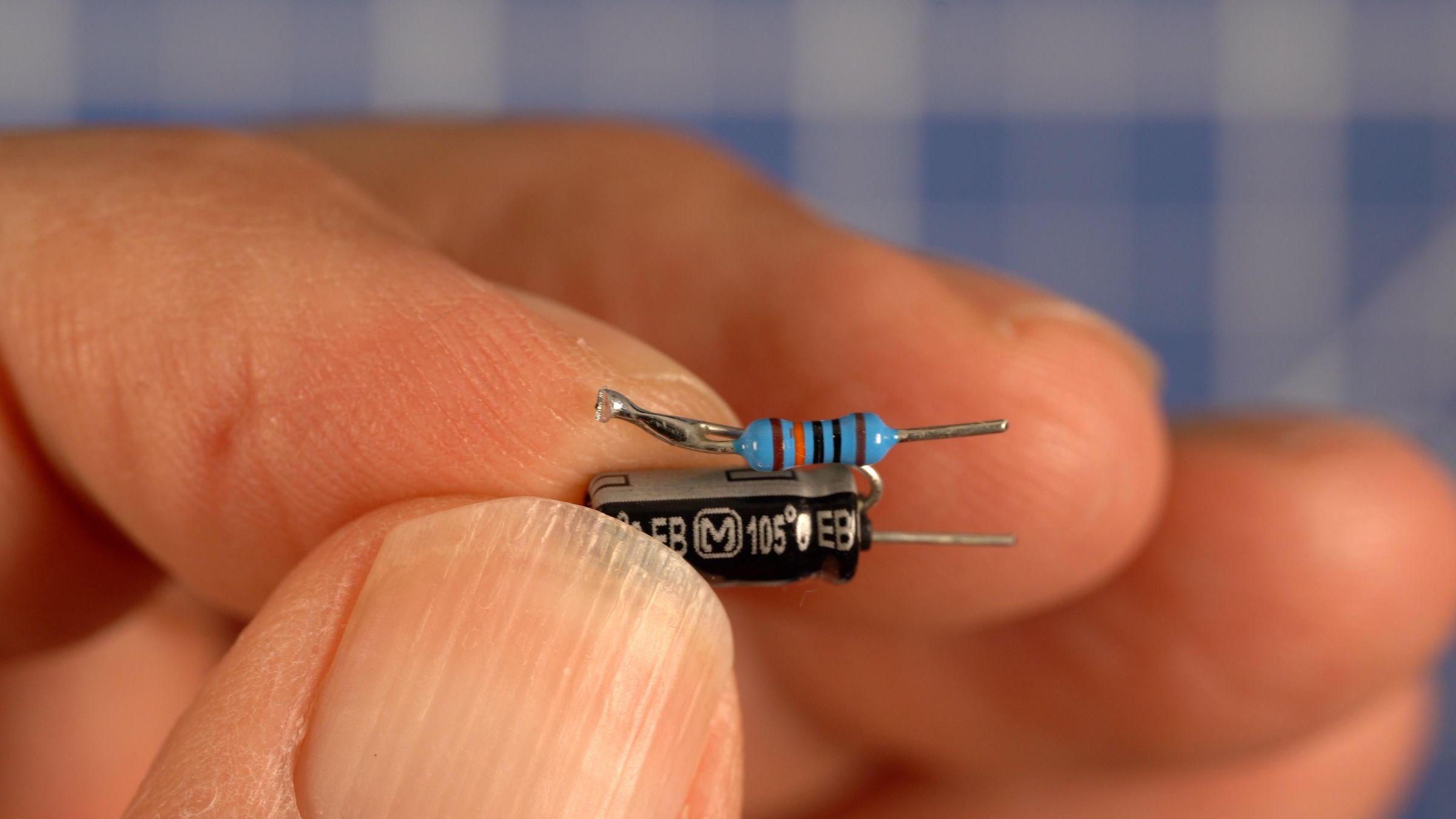
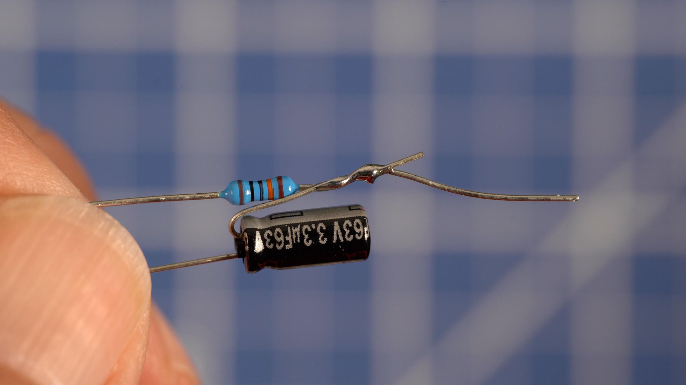
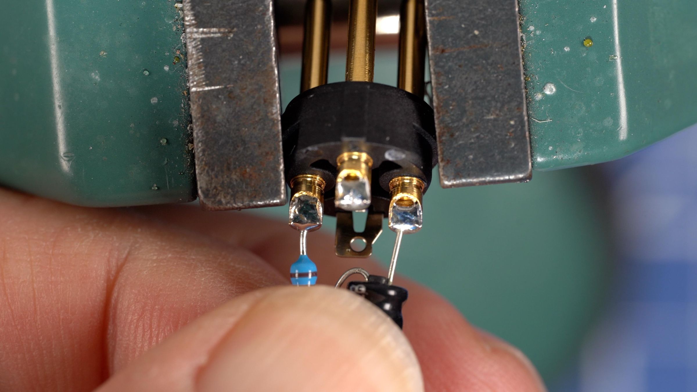
Our first step is to build the 8 microphone sections that will mount on the microphone. We start at the XLR end and solder the Simple P48 components. Bend the lead up on the negative side of the capacitor so it runs alongside the body. Now twist that lead with one of the resistor leads so that the other lead and the “+” lead of the capacitor face down. Solder the twisted leads together and trim them so they are even with the top. See the photos.
Step two is to prep the XLR connector. Put the XLR body in a small hobby vice and tin the three solder cup terminals.
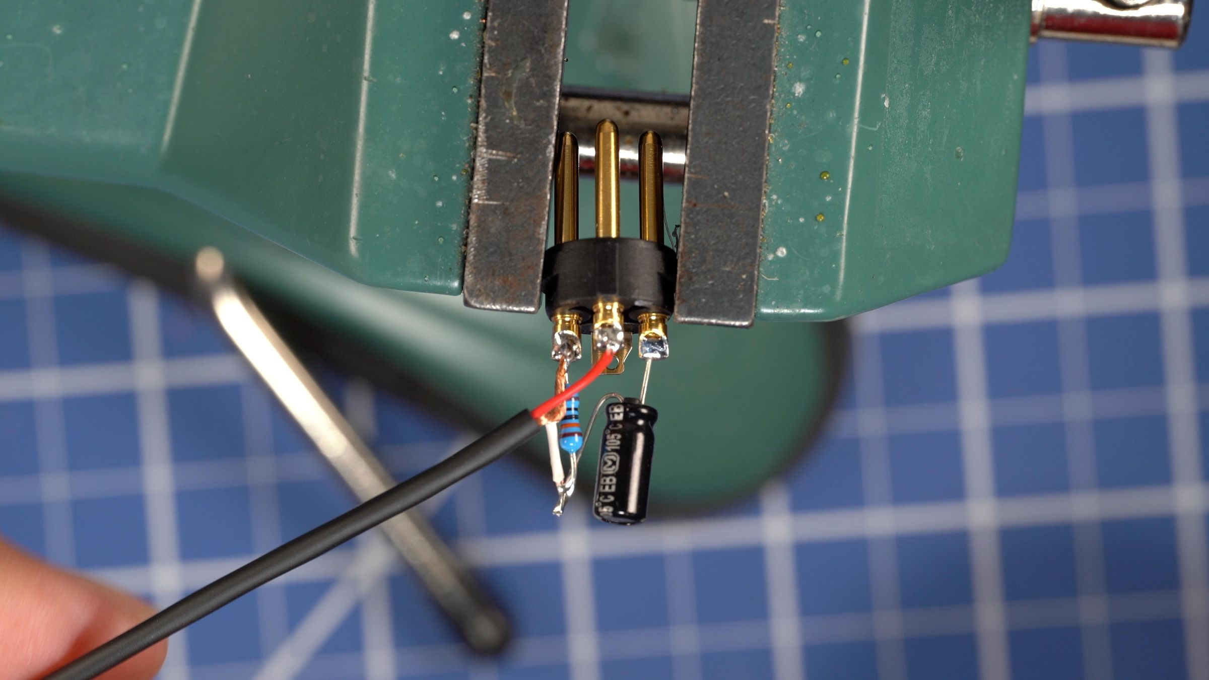
Step three, solder the resistor capacitor assembly to the XLR body. The resistor lead goes to Pin-1 and the “+” capacitor lead goes to Pin 3. They are across from each other. Repeat this for the rest of the connectors.
Now we prepare the cable.You will need to cut 8 equal lengths. I recommend 10 ft as the minimum. That lets you put the mic up on a stand and have the recorder connected below it. Interestingly the XLR connectors are the heaviest part of the mic with the cable a close second.
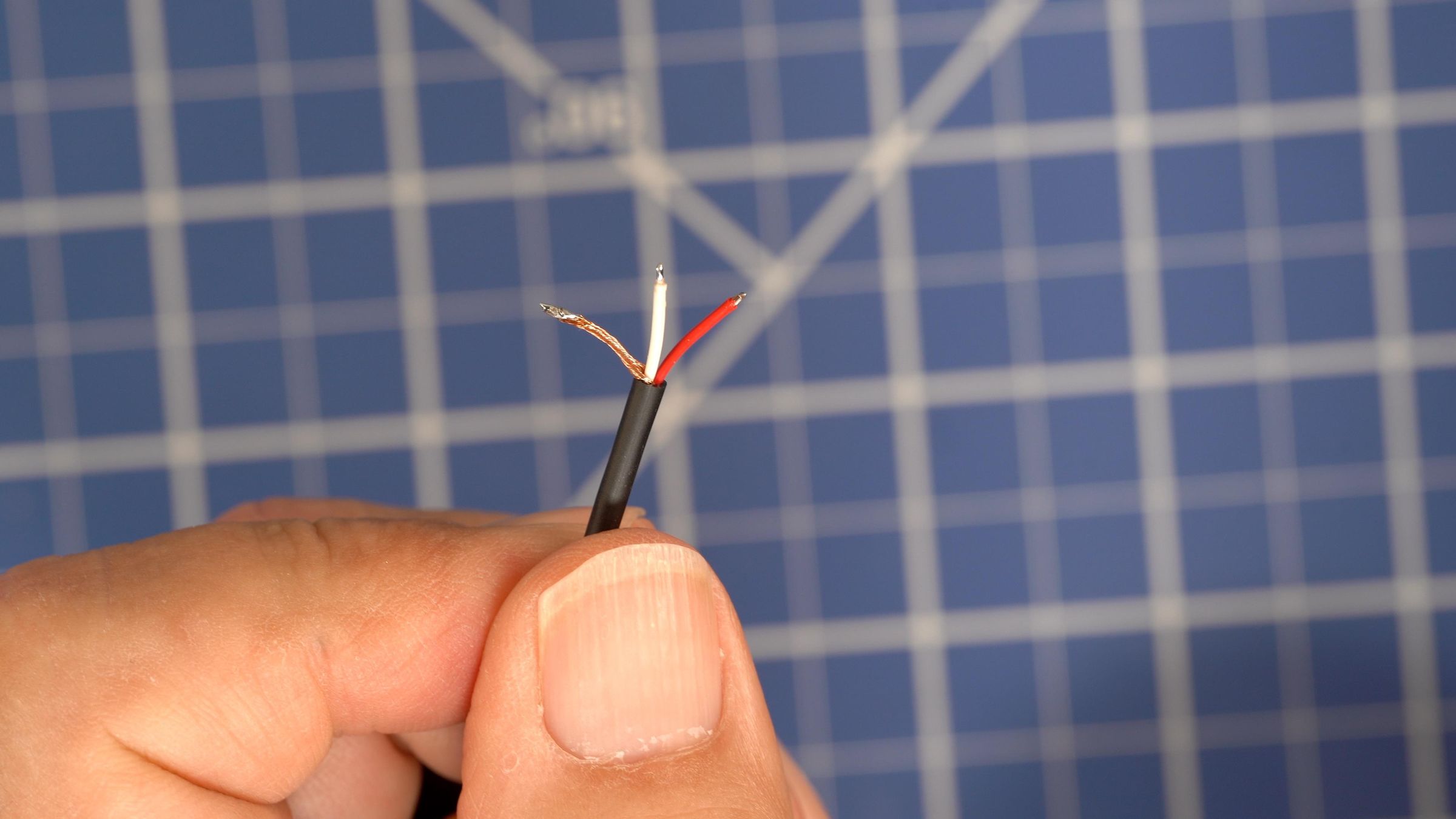
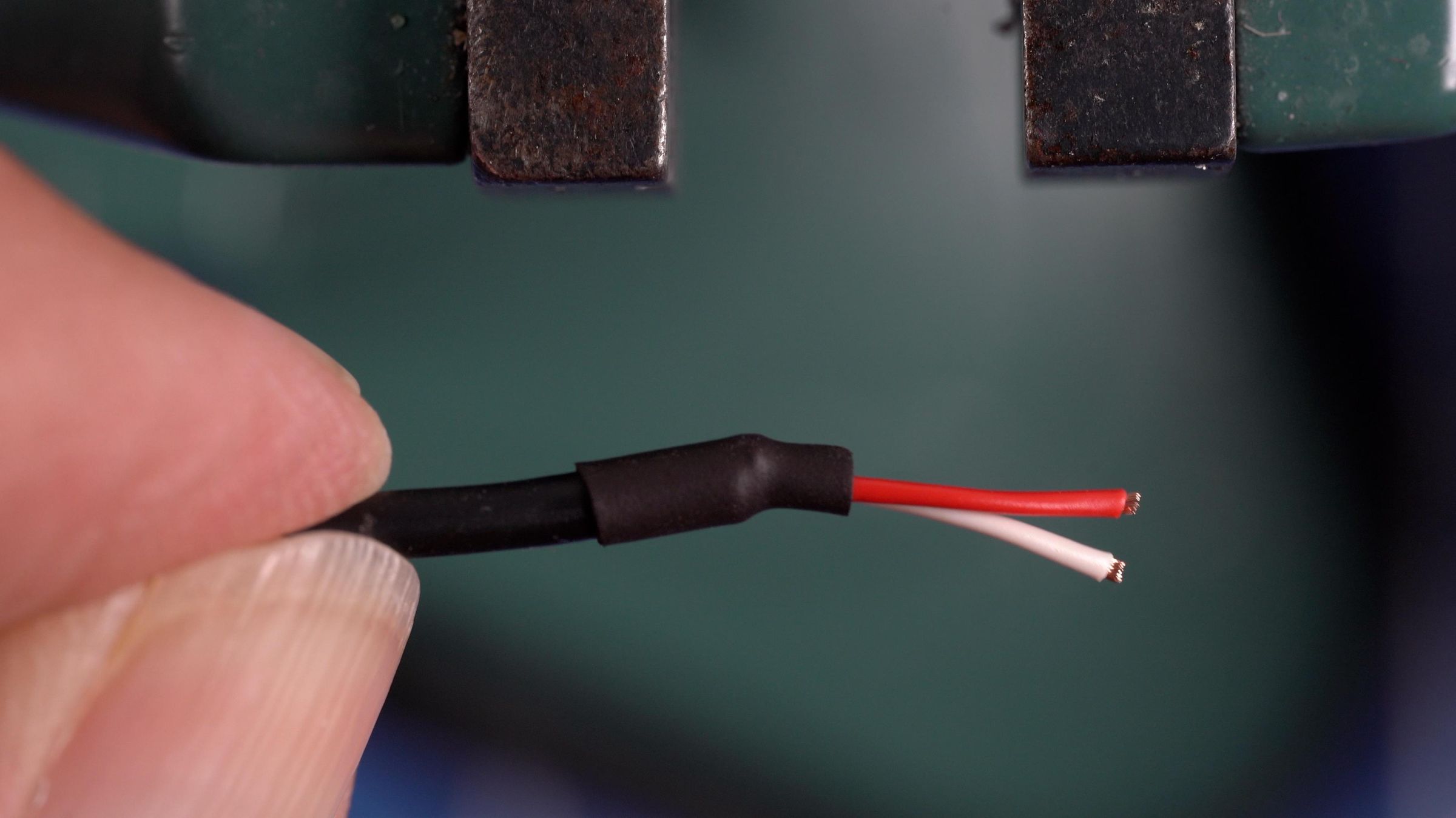
We are going to prep the capsule connection side of the wire first. This one gets a small piece of heat shrink tubing on it and that part is delicate. Trim back the outer insulation about ¾”, twist the shield over to one side and cut it off as close to the insulation as possible. Place a short piece of ⅛” heat shrink tubing over the insulation leaving the white and red wires sticking out. Our goal here is to ensure no pieces of the shielding are exposed that could touch the capsule metal. Remember, the capsule is electrically floating and is NOT tied to ground. Carefully and quickly shrink the tubing using a hot air gun. Do not use a lighter or open flame. As soon as you see the tubing shrink down pull it away from the heat. Too much and you will melt the white and red insulation of the two inner wires. How do I know?... We can discuss that over coffee. I encourage you to practice this one as we will be doing multiple of these. Once you have this down, repeat for the other capsule cables. Another tip for making this all go smooth is to use a small velcro wrap to tie each wire into its own little cable. This cable can get twisted up pretty quickly when left to flop around. Keeping all the capsule and wires separated in neat coils makes the rest of the assembly much easier!
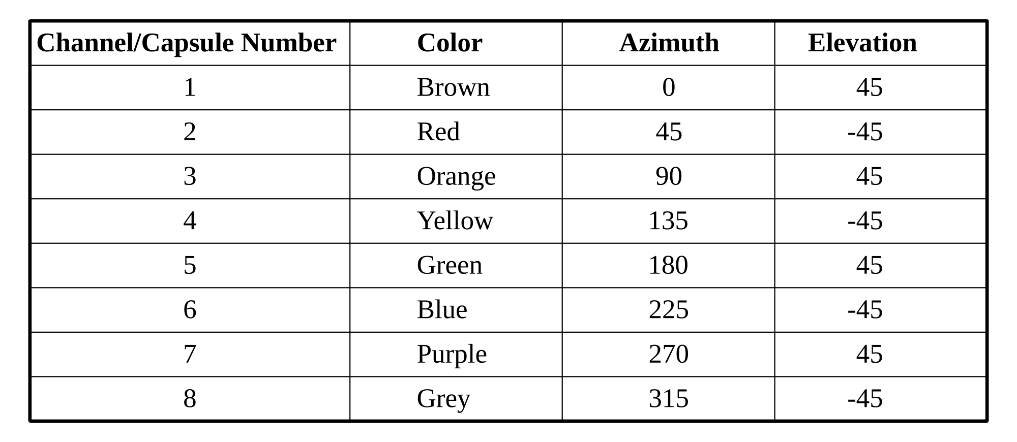
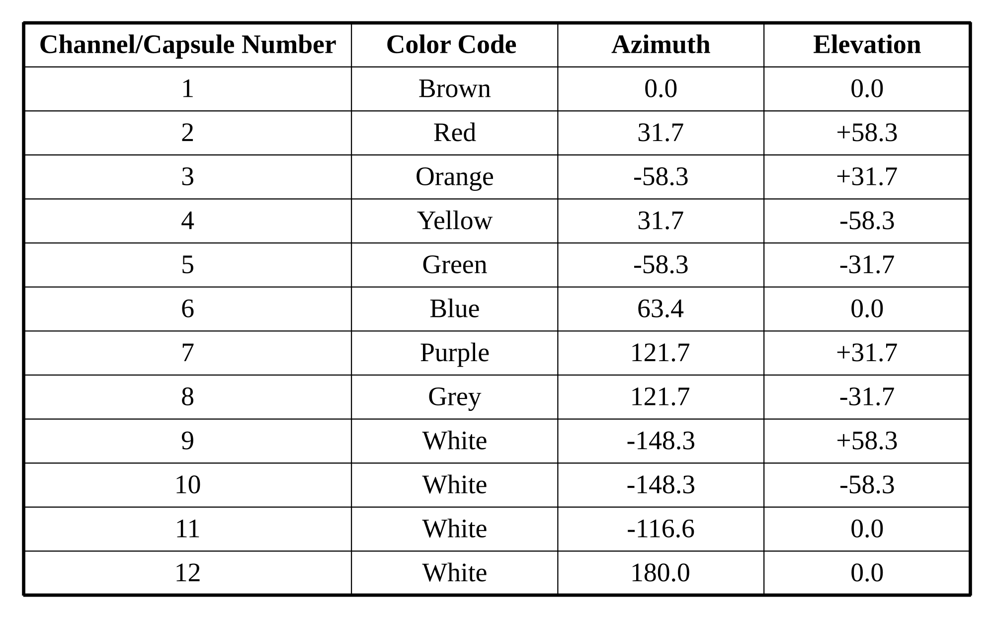
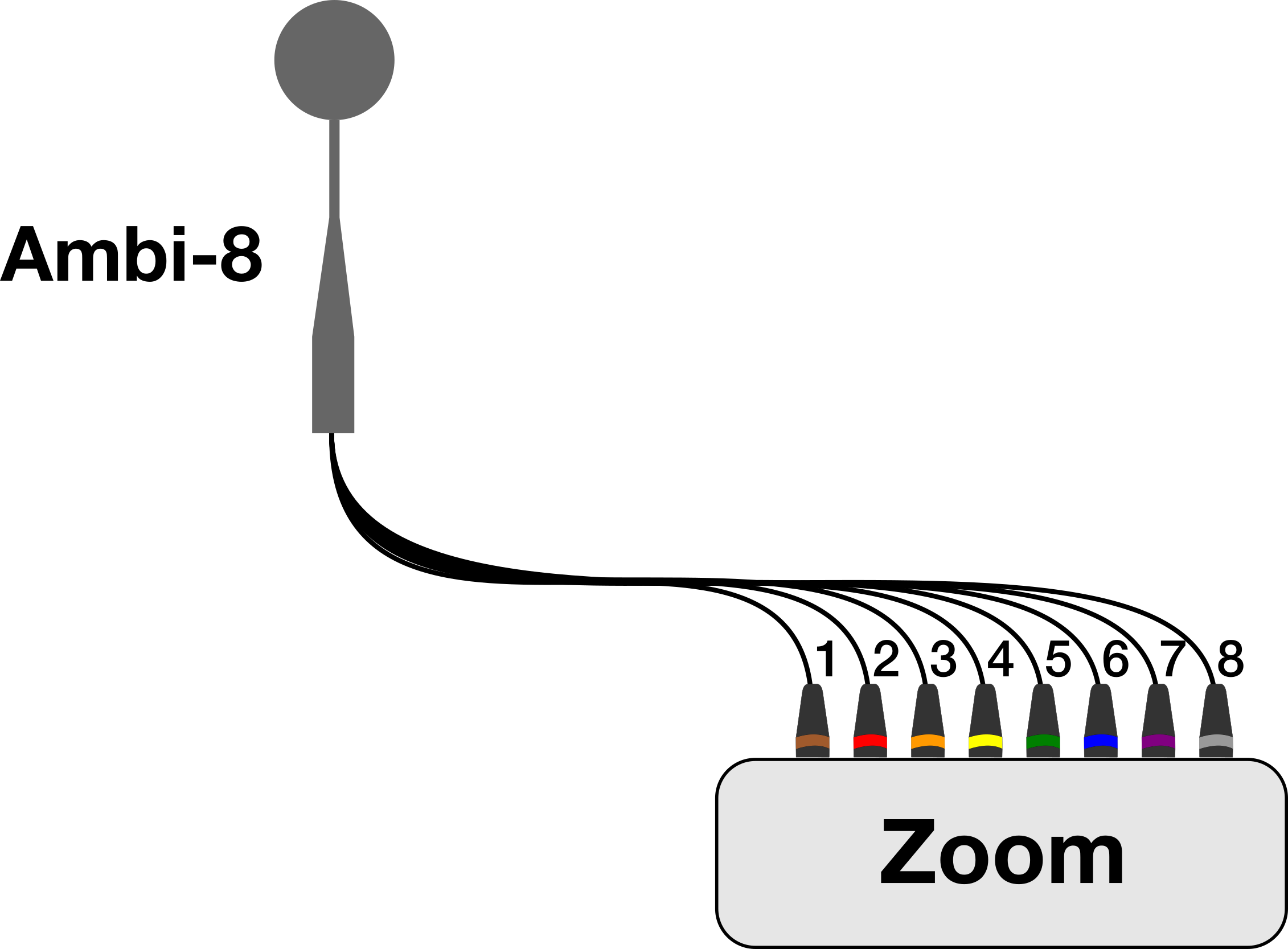
Now prep the XLR end by inserting the wire through the colored boot. We are using resistor color coding for the channel numbers: Brown, Red, Orange, Yellow, Green, Blue, Purple, and Grey. Those are for channels 1-8. For the 12 channel version I used 4 white XLR boots and channel numbers for both the capsules and the XLR connectors. I messed this up on my first build of the 12 capsule mic. Lesson learned here…
From the end of the wire we just pulled through trim back about 1/2 inch or so of the outer insulation. Then twist the shield wires together and pull to one side. Then strip just a bit of the red and white insulation off of the white and the red wires. Tin the ends of all three. Solder the shield connection to Pin-1 Ground, Red to Pin-3 and the White wire to the resistor capacitor junction. Now repeat that for the remaining capsules.
We need to test them before we proceed. Connect them to a recorder and ensure they work. Headphones help here. They should all sound the same and be at the same volume level.
Our next step is to mount all the capsules into the capsule holders. The holders print with a slit in the side so we can pop the wire in. Use a small amount of E6000 glue to hold them in place. Let these dry overnight.
Mechanical Assembly: the Ambi-8
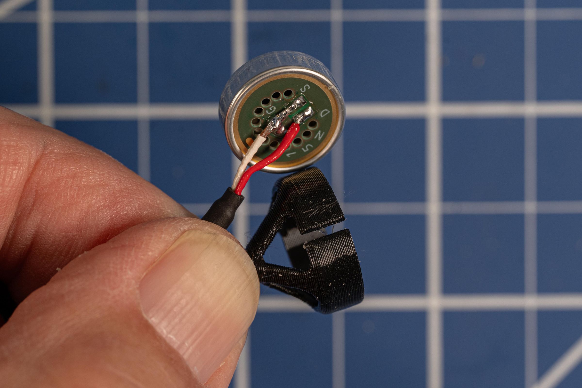
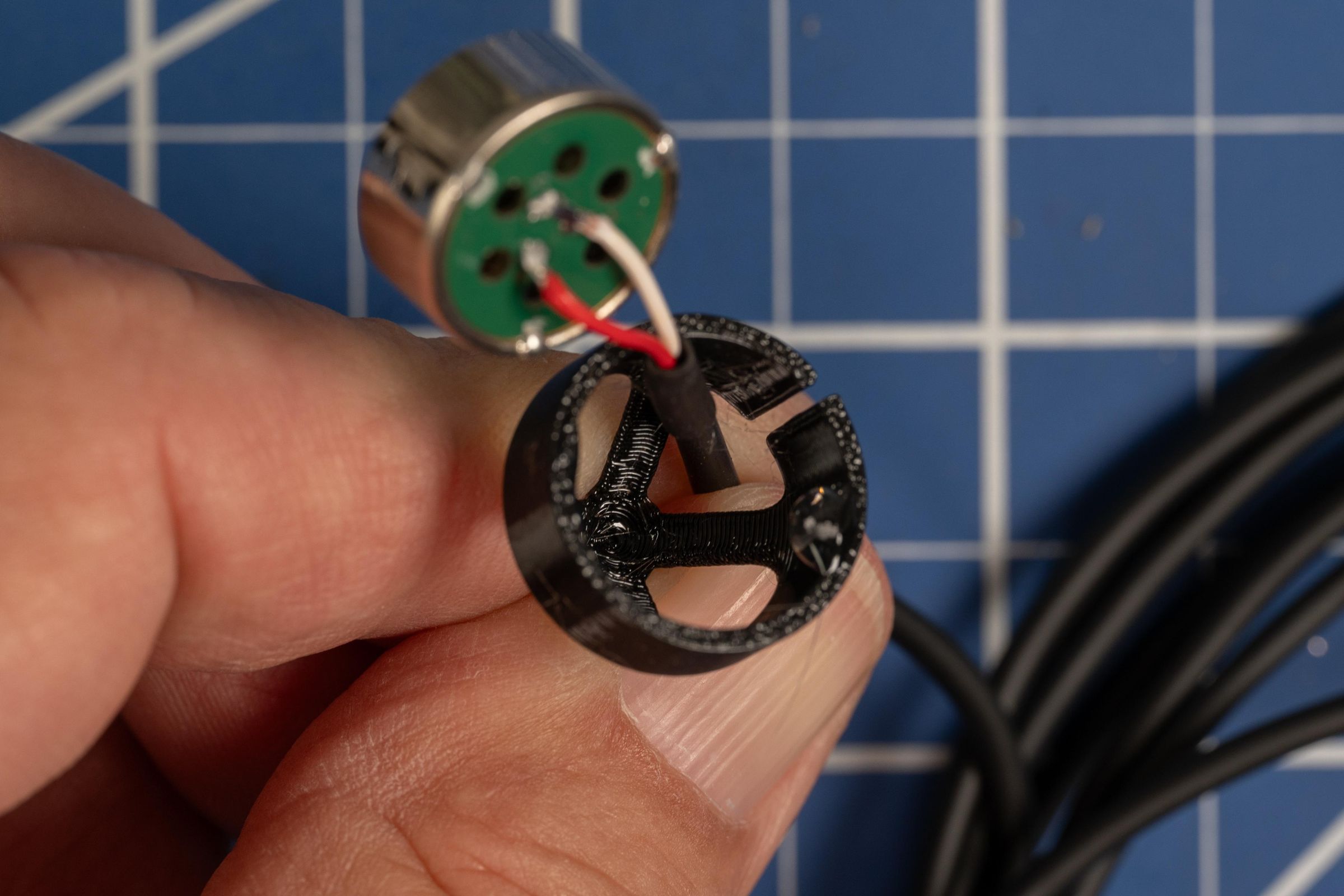
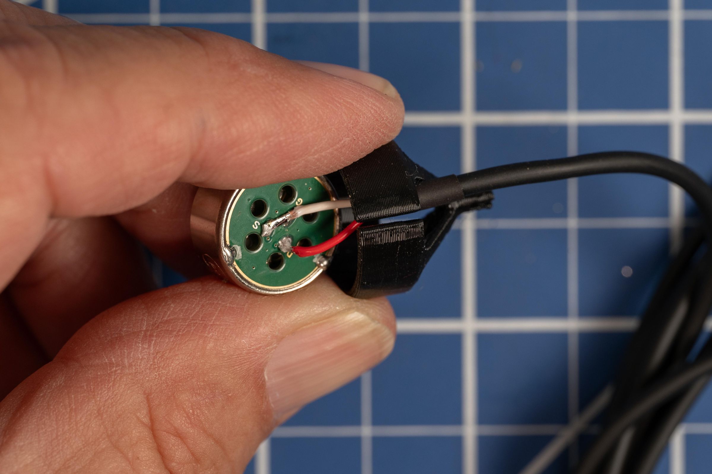
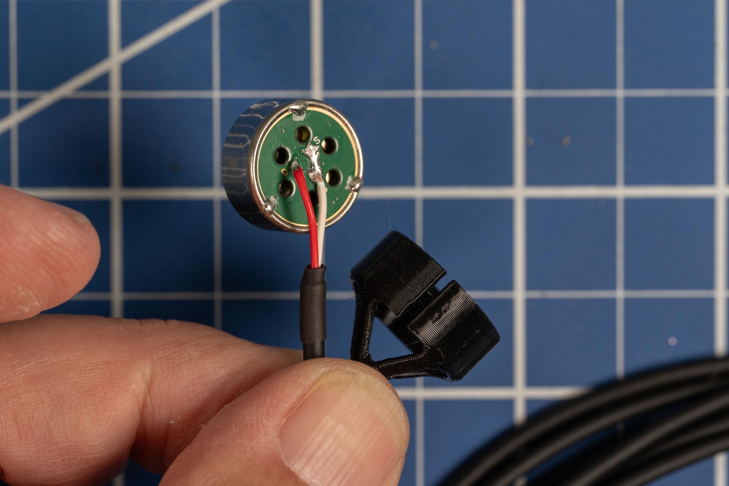
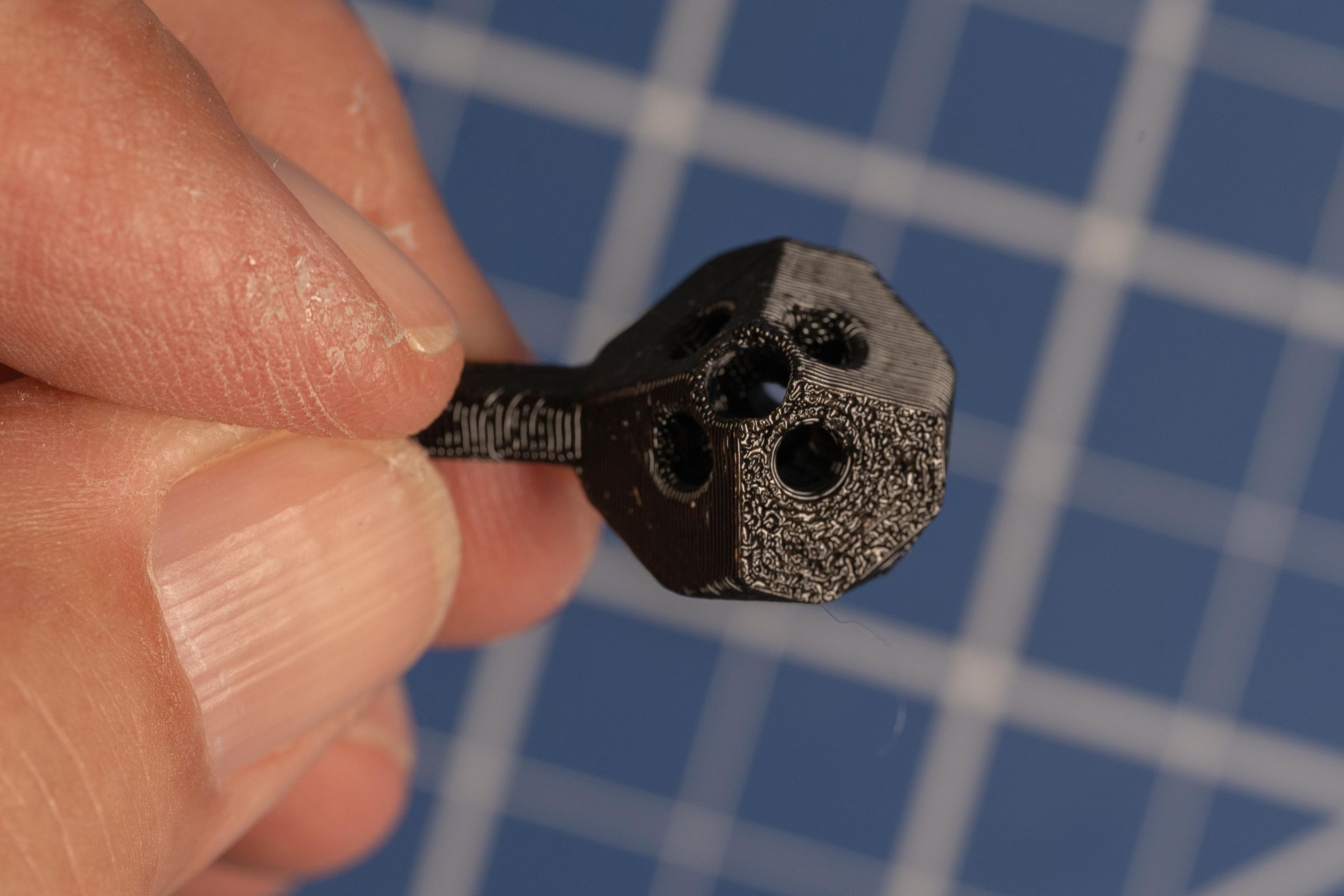
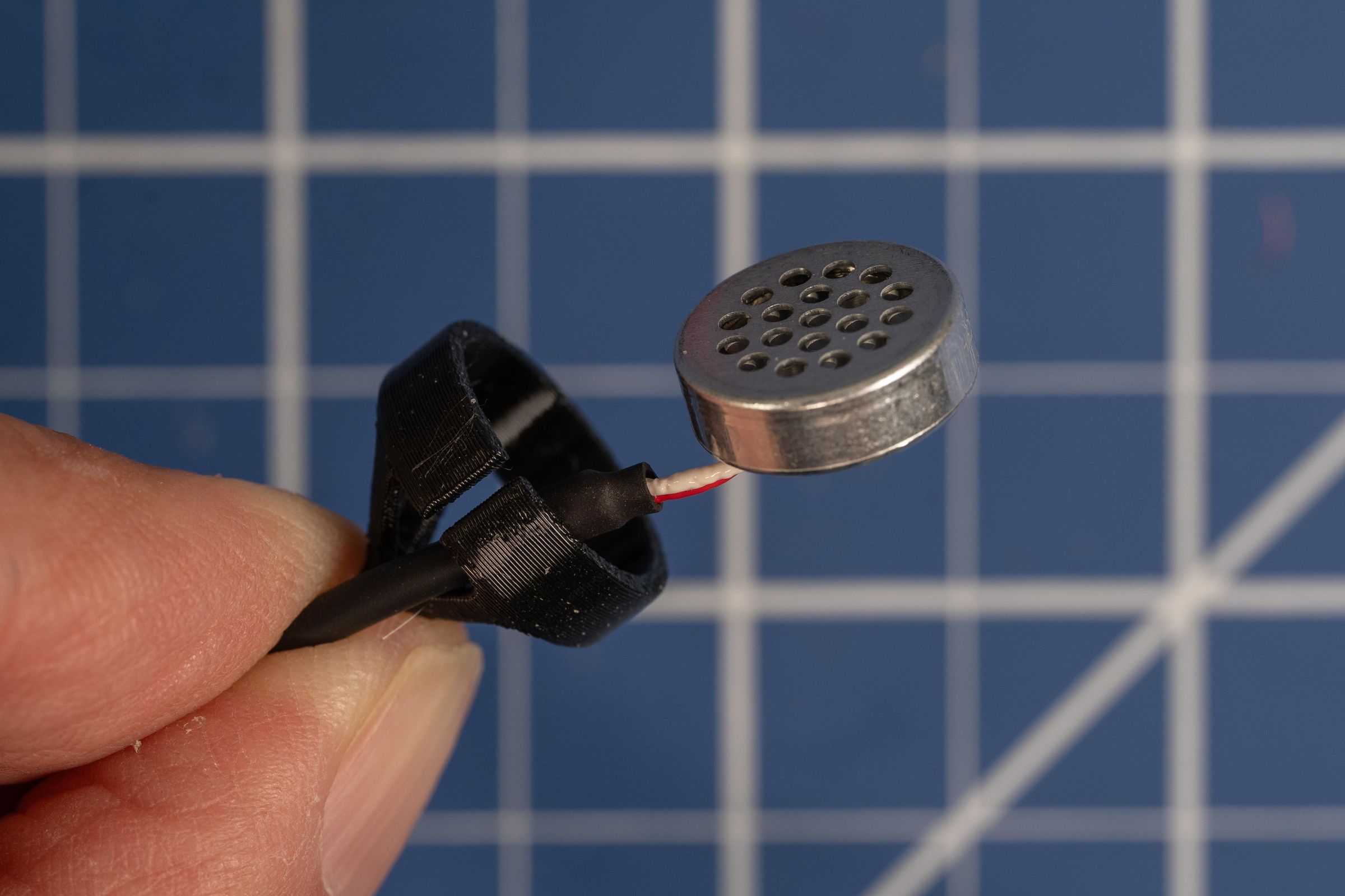
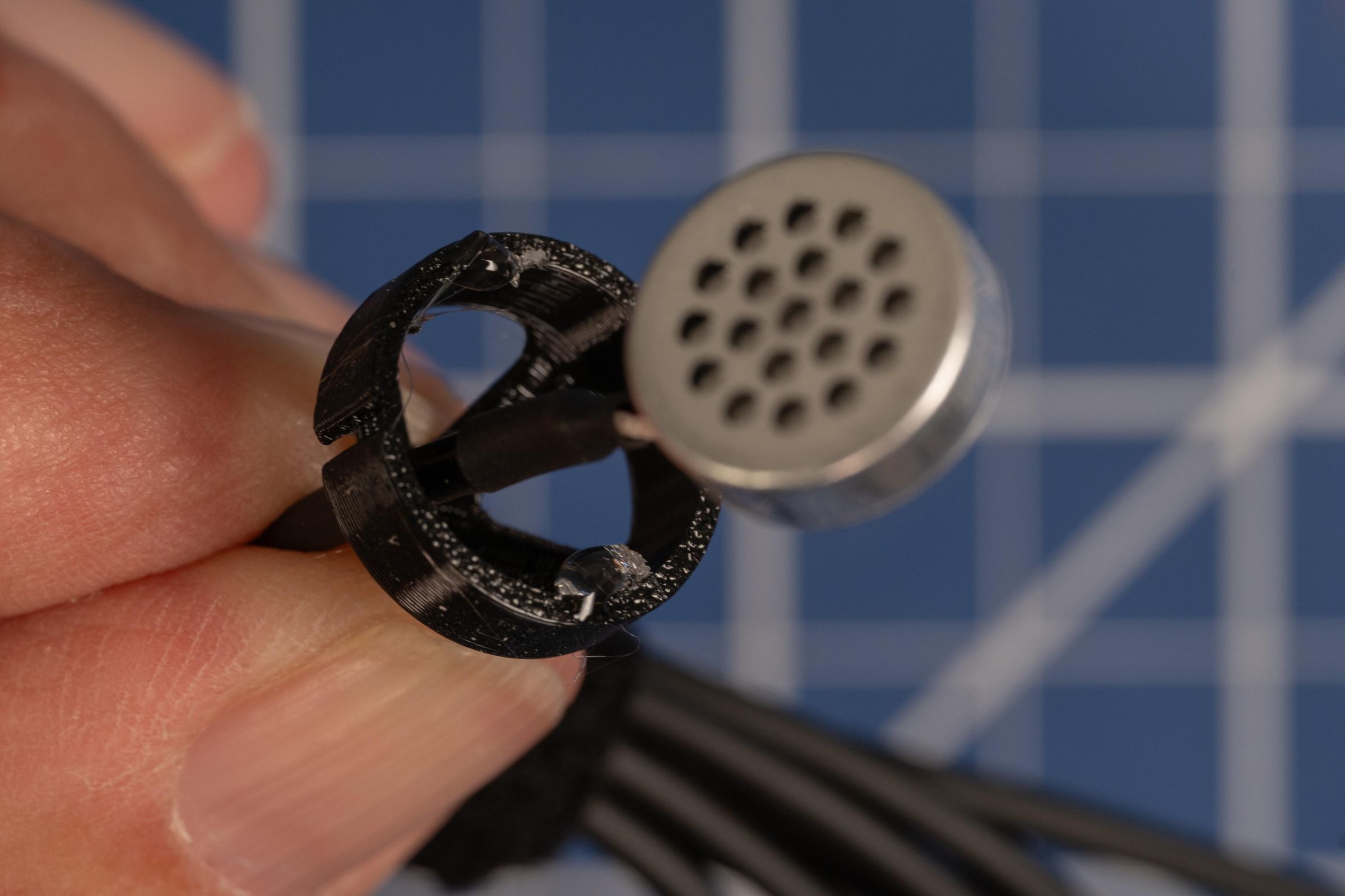
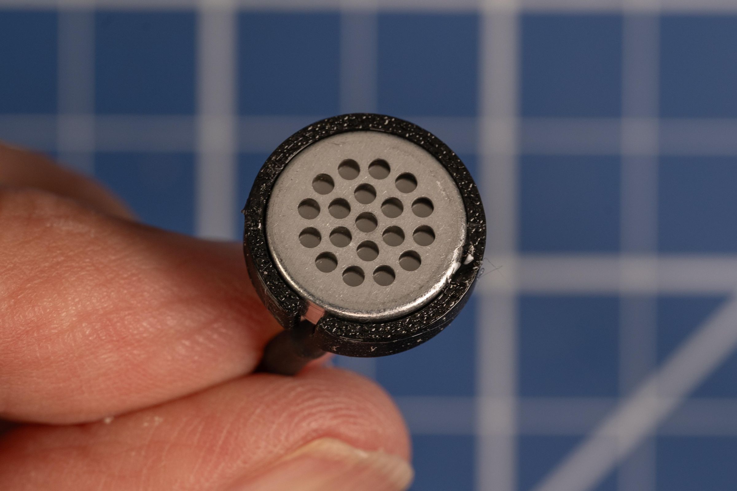
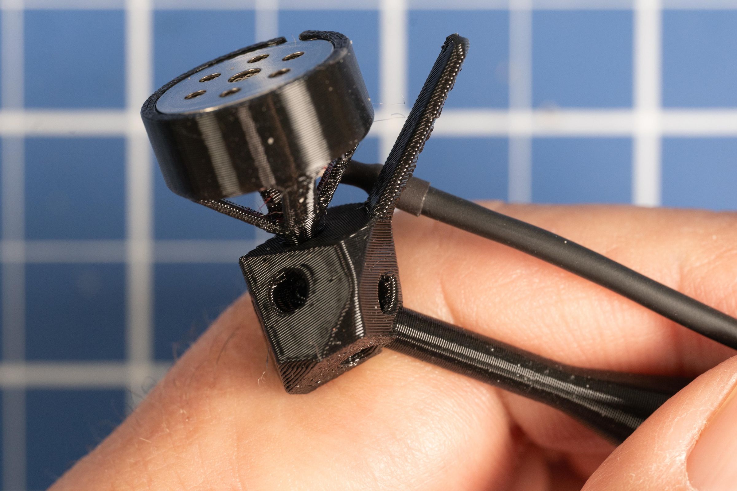
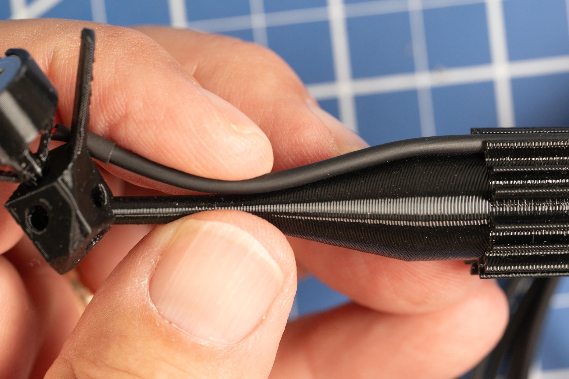
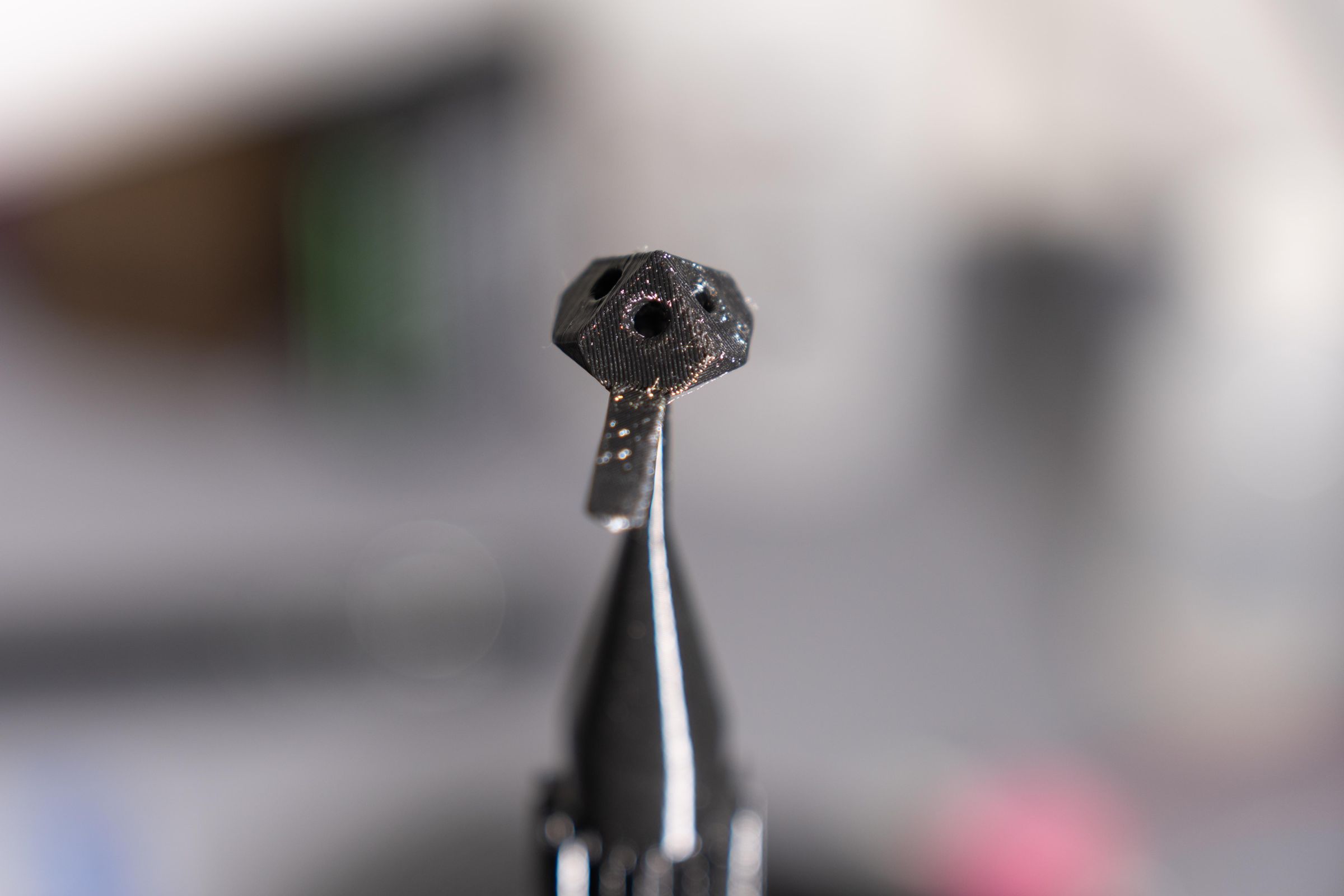
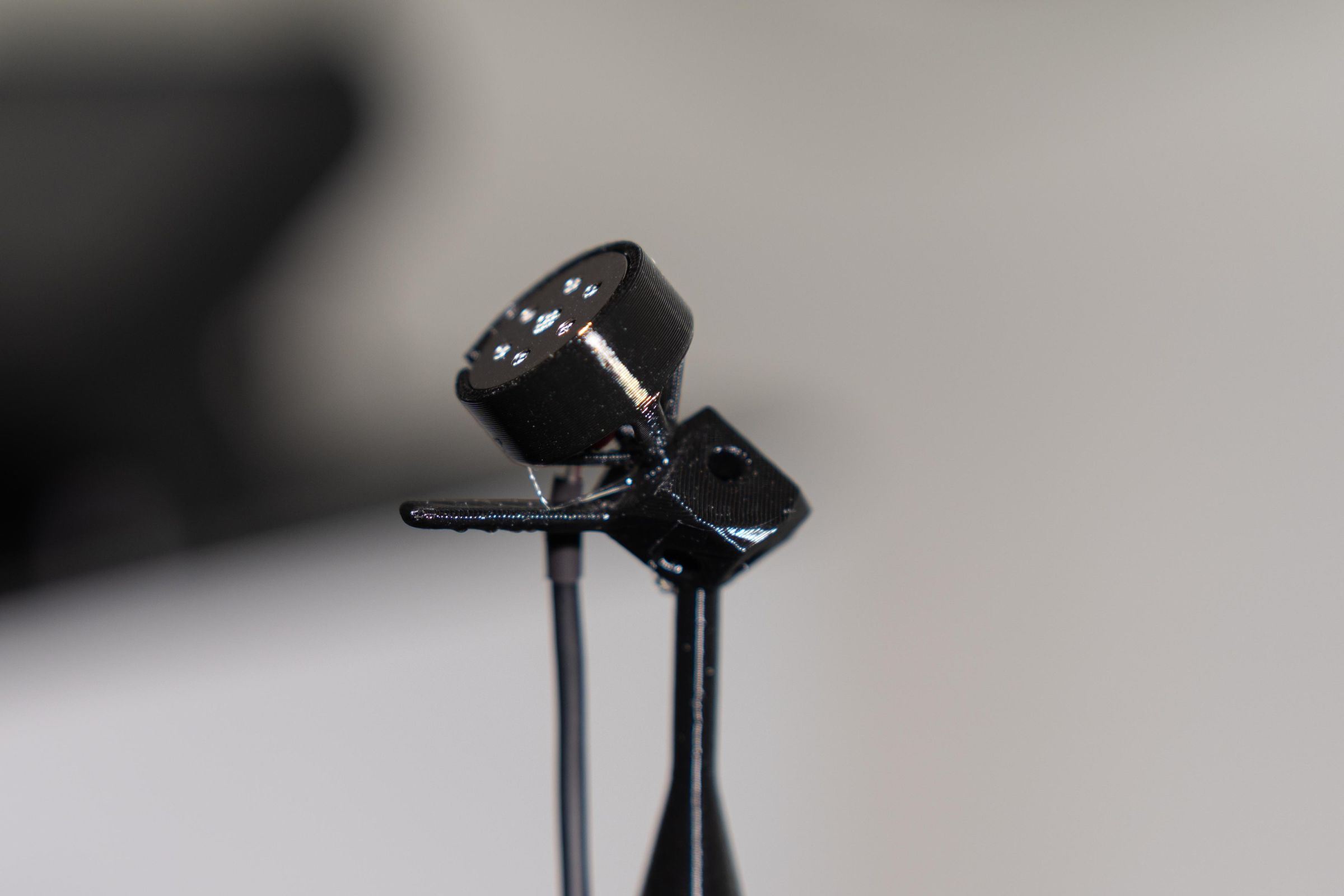
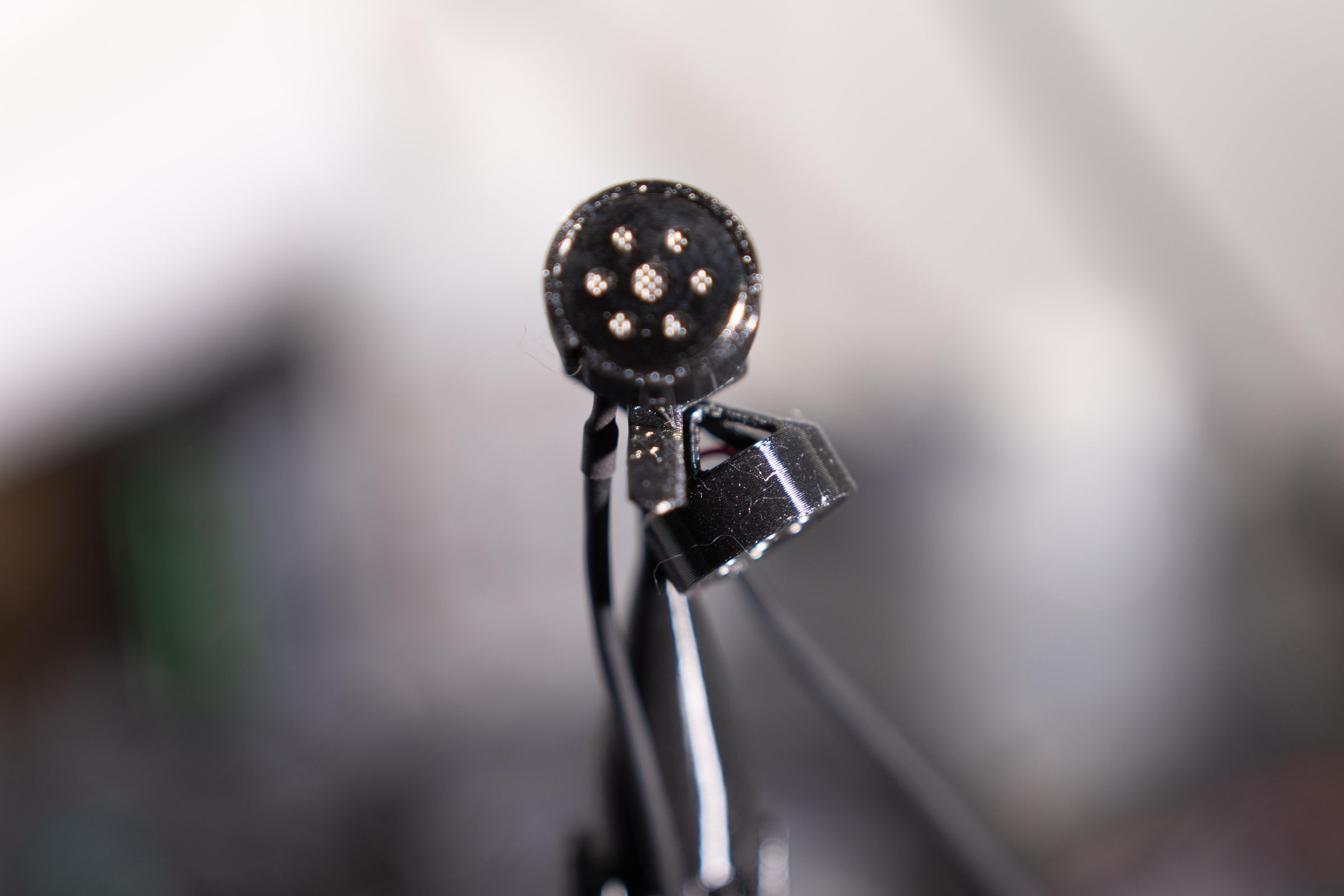
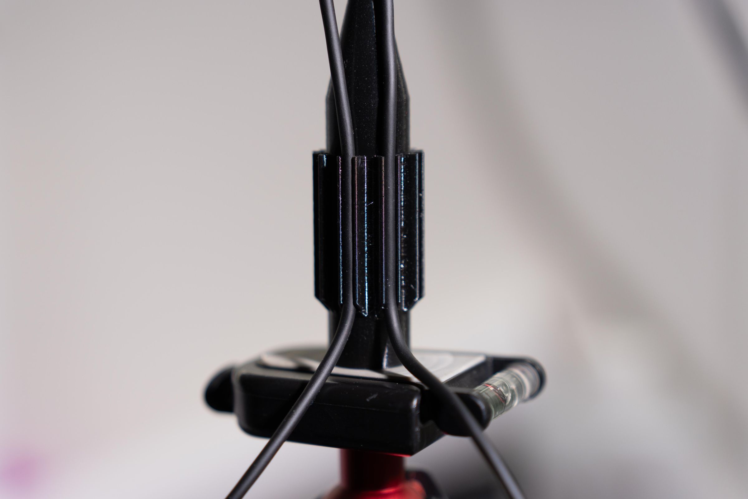
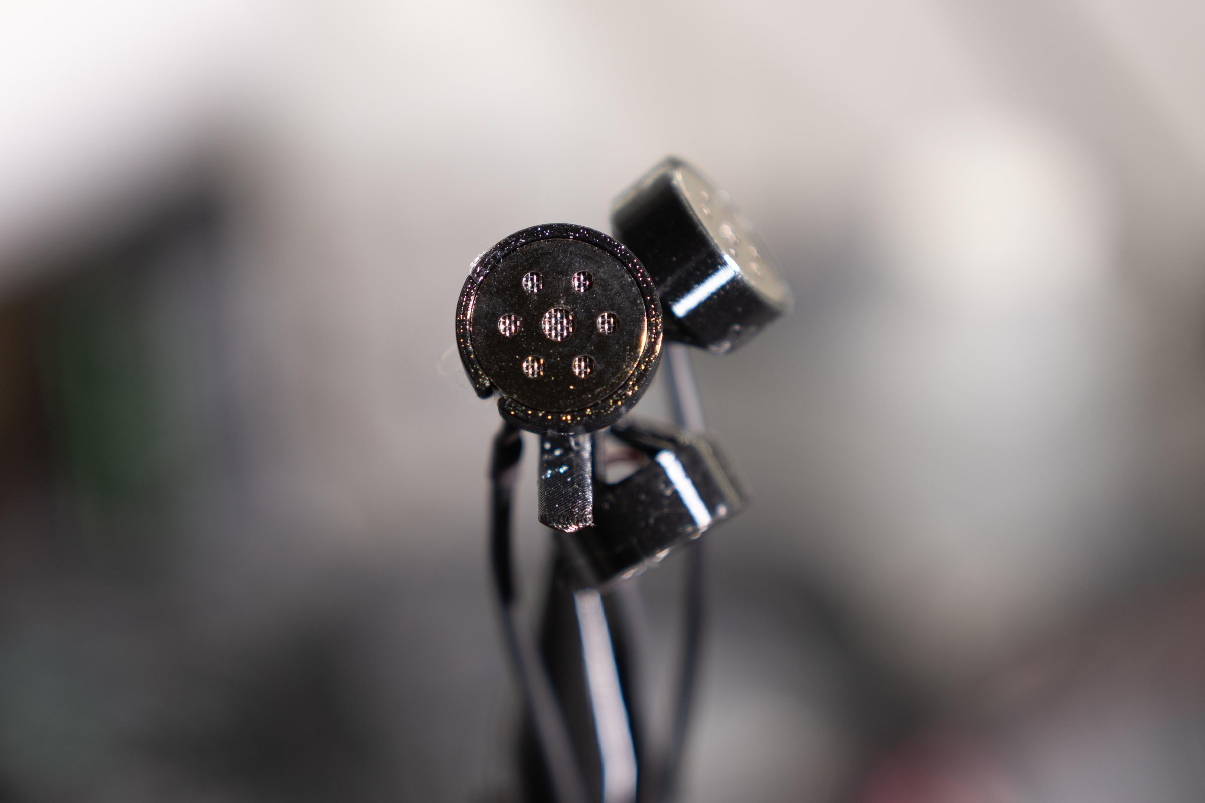
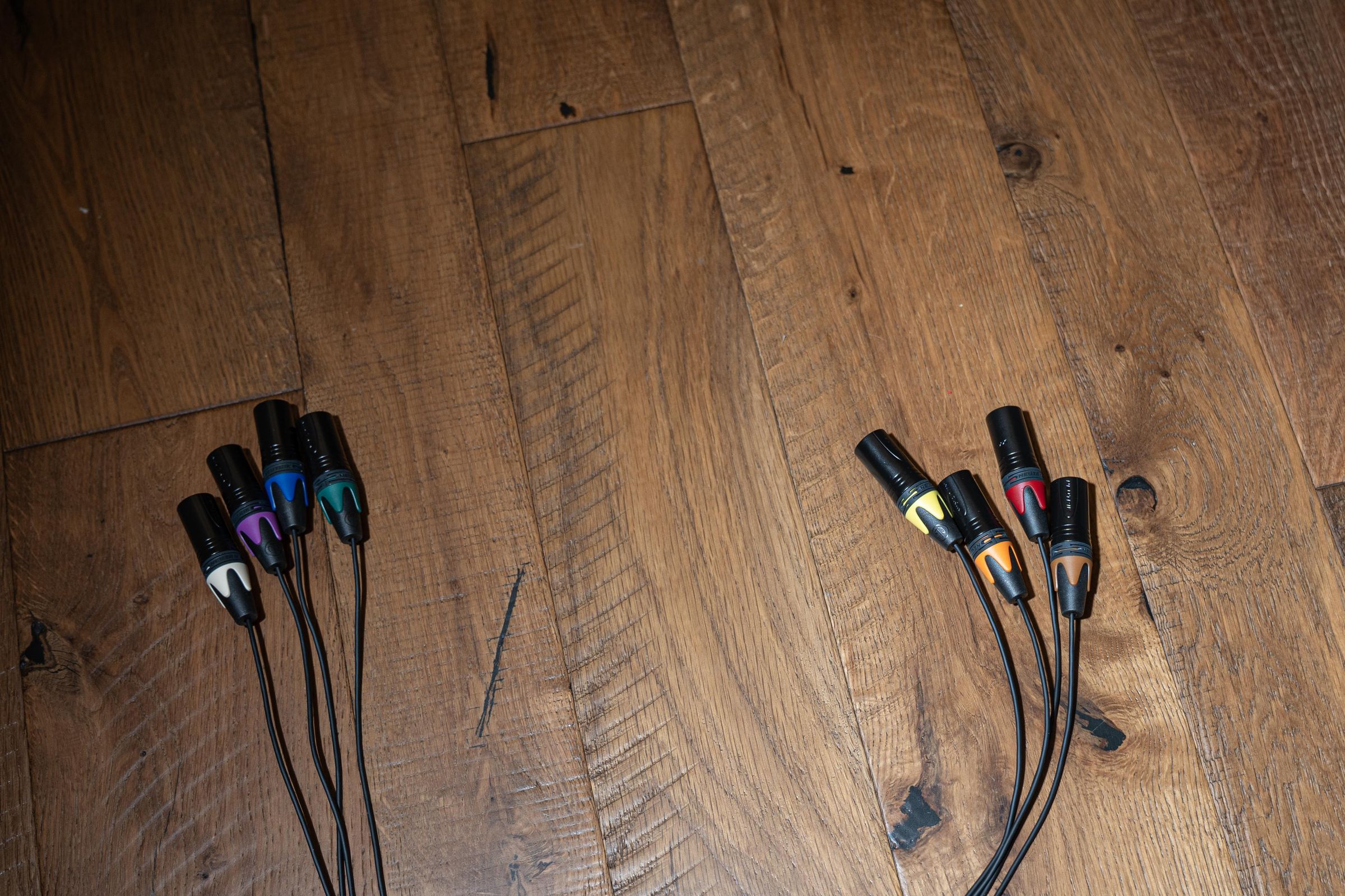
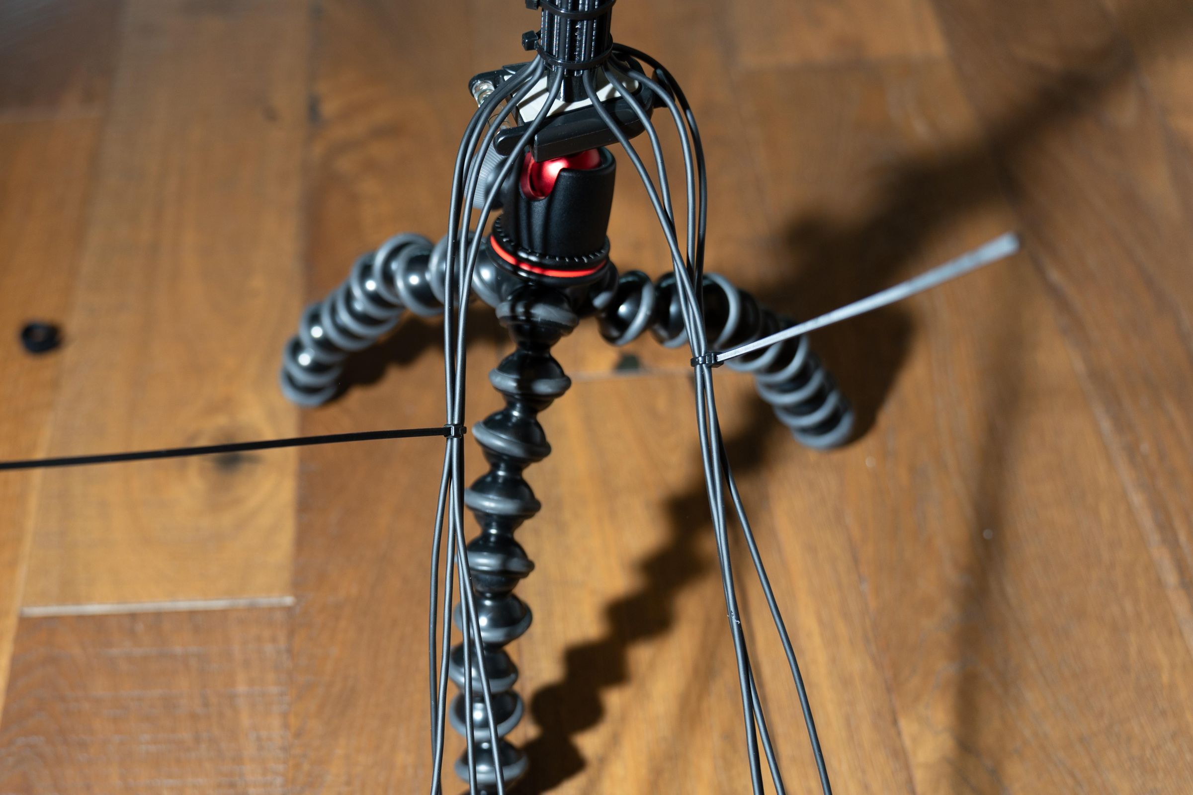
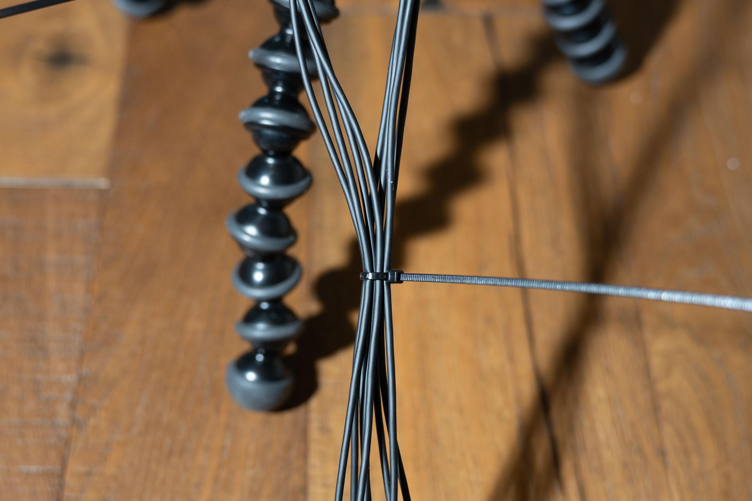
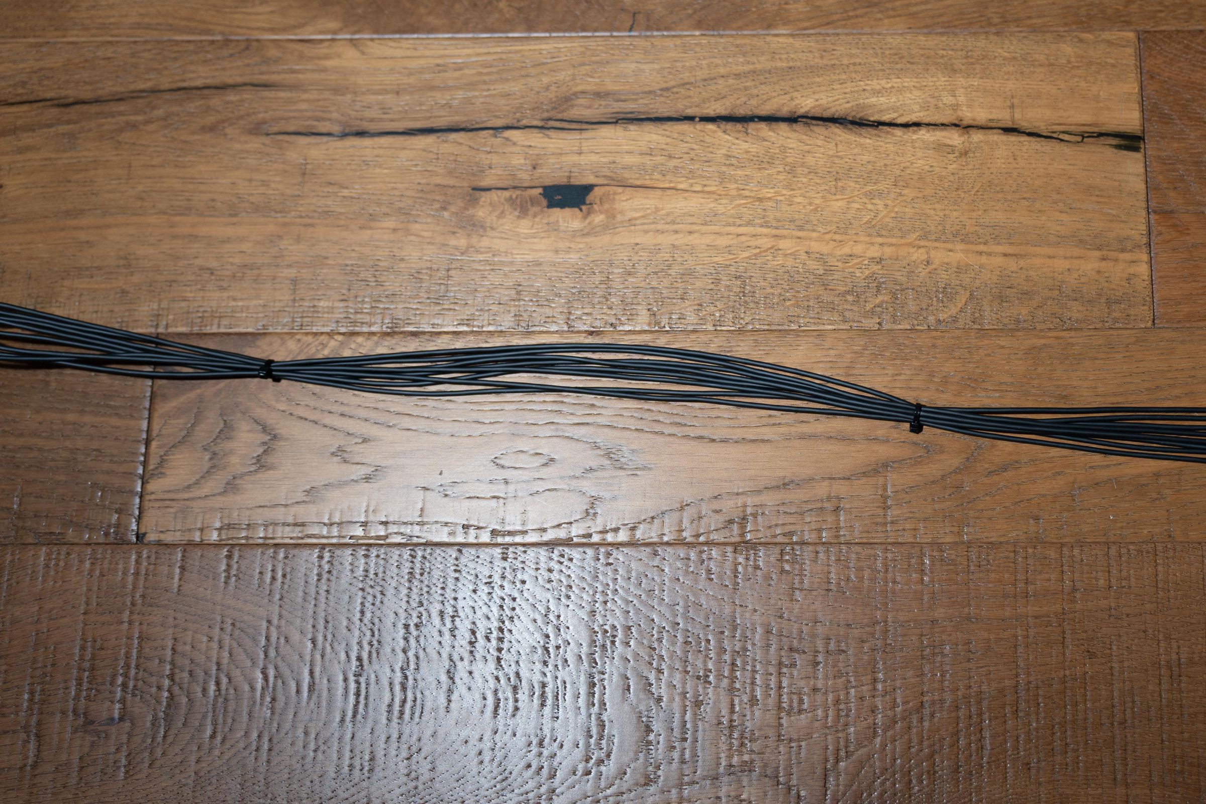
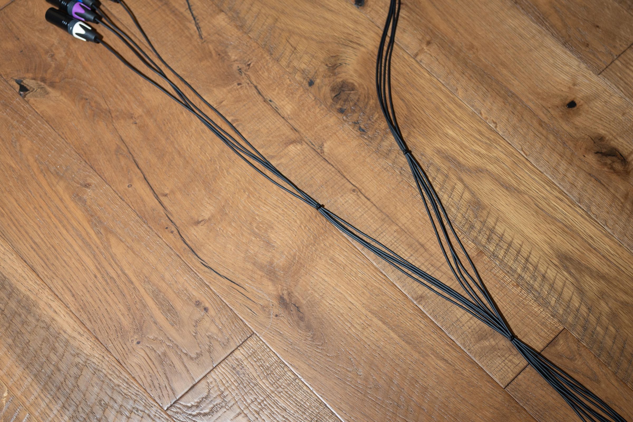
Now it is time to assemble the full microphones. Lets do the 8 capsule one first as this is the easier one. Visually inspect the geometry part: the “duck head”. We want to ensure that we can insert a capsule holder into each of the eight holes without blockage.
Install the ¼-20 brass insert. Place the base in a hobby vise with the bottom facing up. Place the insert in the hole. With a hot soldering iron warm the insert and apply an even but gentle force. When the brass insert melts the insert will move into the hole. If you have never done this before print an extra base and practice. Press it in until it is flush.
Now insert the top of the base into the “duck head” shaped base. Use just a tiny bit of E6000. Note that the end of the holder is tapered at a 45° angle. This allows the hole for the lower capsules to remain intact for the lower capsule mounts. Let this dry.
Mount microphone base on a small tripod with the front facing you. We need to keep track of the capsule ordering and channel assignment. The top/front capsule is #1. and the capsule to the lower right is #2. Above and to the right of capsule #2 is capsule #3.
- Top ring of capsules: #1, #3, #5 and #7
- Bottom ring of capsules: #2, #4, #6 and #8
This is the fun part. Starting with Capsule #1, put a small amount of E6000 glue on the tip of the capsule holder prong and insert it in the hole above the direction indicator. Press the Mogami wire into the wire holder below it. The goal is to keep the wire close to the thin part of the mic body but not block any of the holes below it. Press it in firmly so that it is fully in the cable management channel. See the photos. Lay the wire for capsule one out neatly so that we can form a wire bundle when all the capsules are installed. While looking at the front of the mic (the duck bill is facing you) insert Capsule #2 into the lower hole to your right use a small dab of E6000 glue to hold it in place when dry. Neatly bring its wire down and press it into the cable management slot nearest it. Press the wire in firmly. Lay the wire out alongside the first capsule wire. Capsule #3 now is installed on the top layer of the mic pointing up 45° and fully to your right from the front. Repeat this for all the remaining capsules.
At this point you should have all the capsules mounted and the immediate wiring dressed into the microphone body cylinder. Take a break and come back and inspect your work. If all the capsules are in the right place, let's continue with dressing in and securing the wires. Place two tie wraps around the cable management part of the mic body to secure the wires. See the photos.
Dress in the wires into one a bundle
Fan the wires out on two slides of the mic body. We are going to form four wires on one side and four on the other. Tie the four on the right side together just below the mic body. These should be the wires for capsules 1-4. Then about 6-8 inches down place a second tie wrap on the same four wires. Repeat this for the left side of the mic body using wires for capsules 5-8. Now tie both bundles together at the 6-8 inch down section. Neatly dress them with a tie wrap every 12 inches leaving the last 16 inches or so free. This lets us get to both sides of a Zoom F8nPro or an 8 channel MixPre.
Mechanical Assembly: the Ambi-12
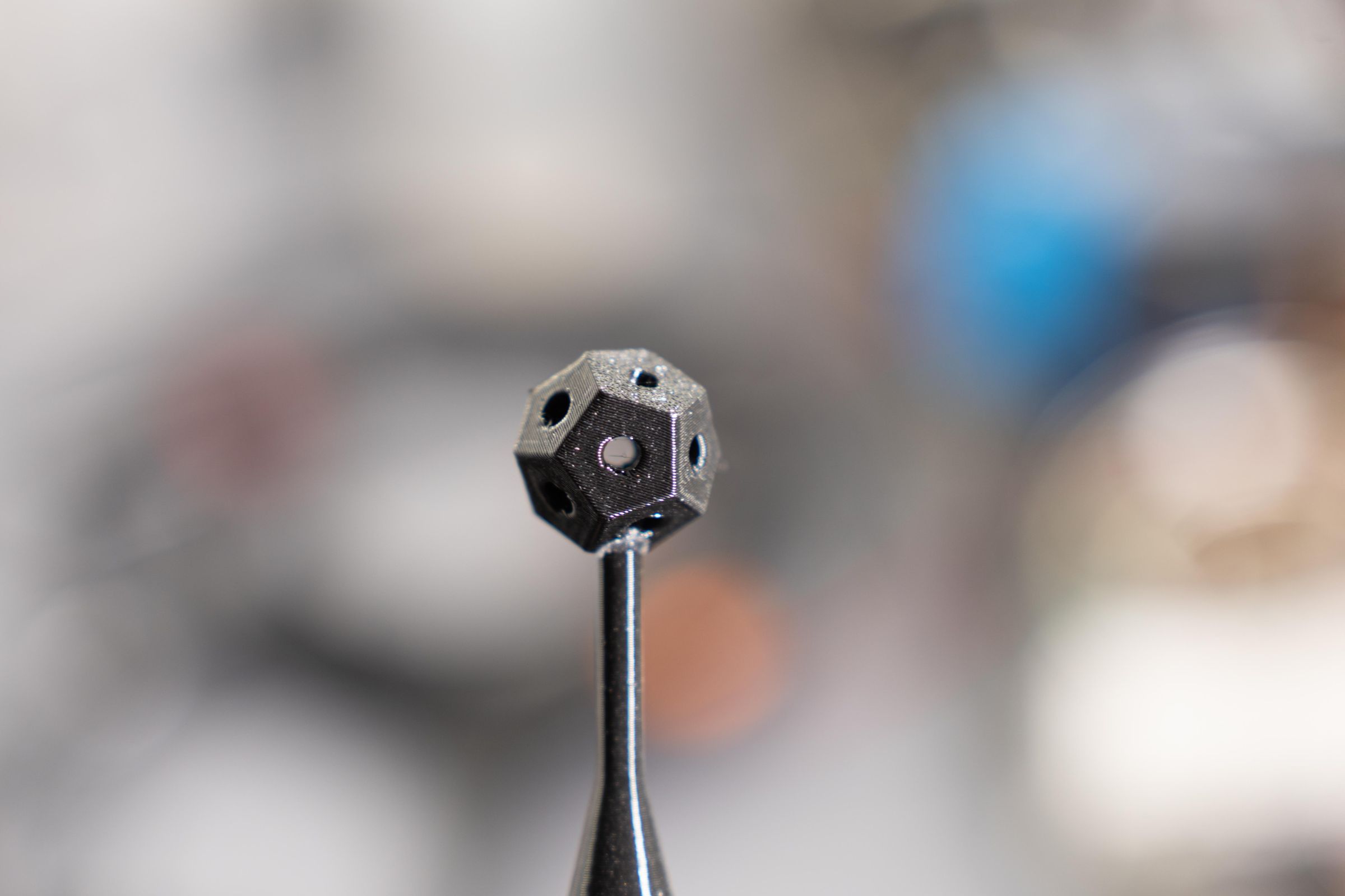
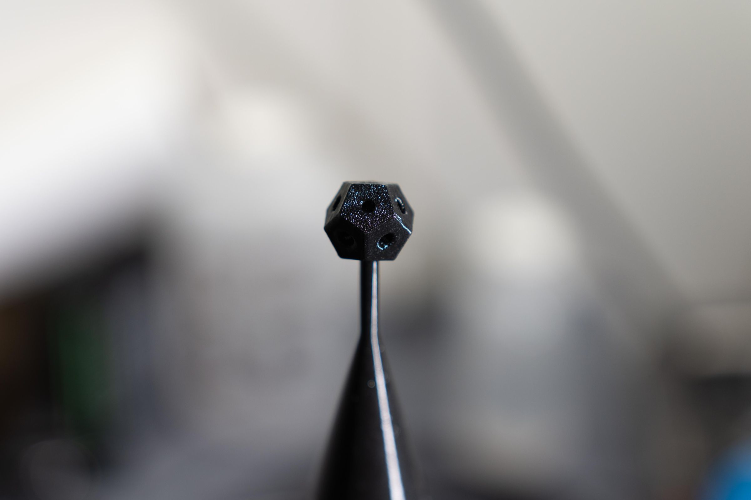
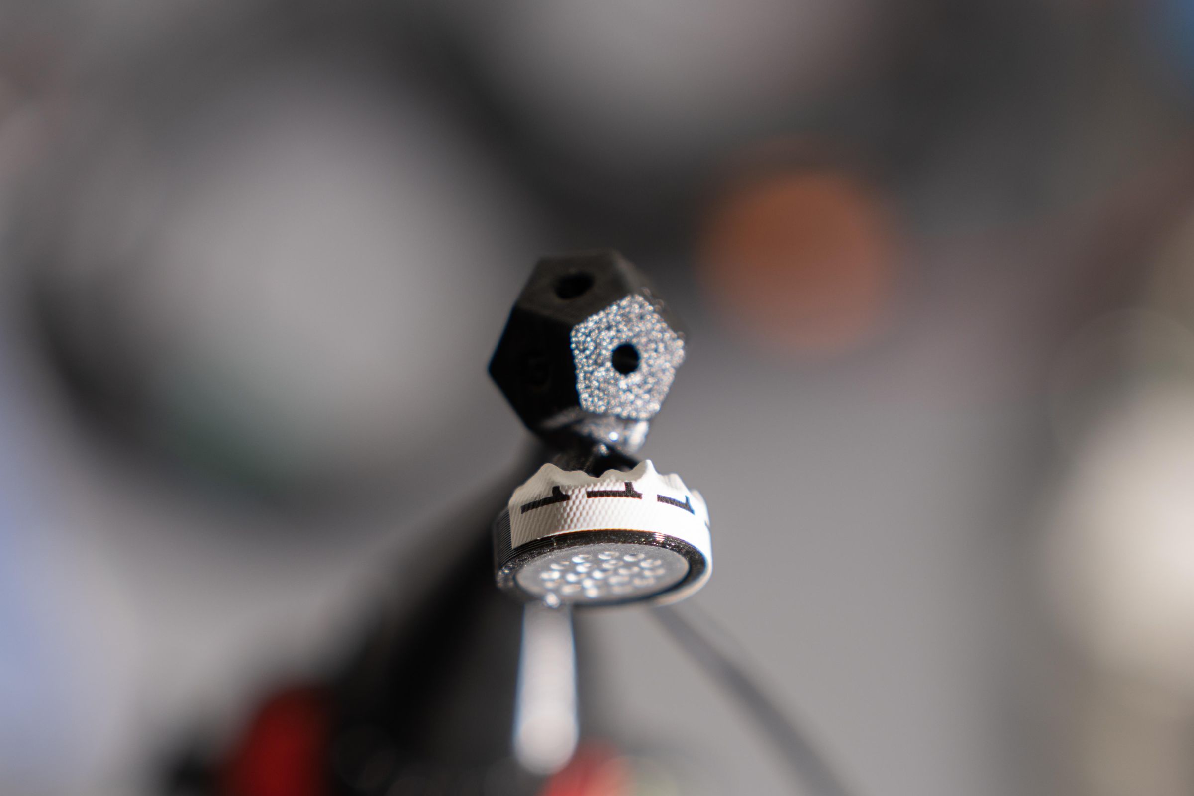
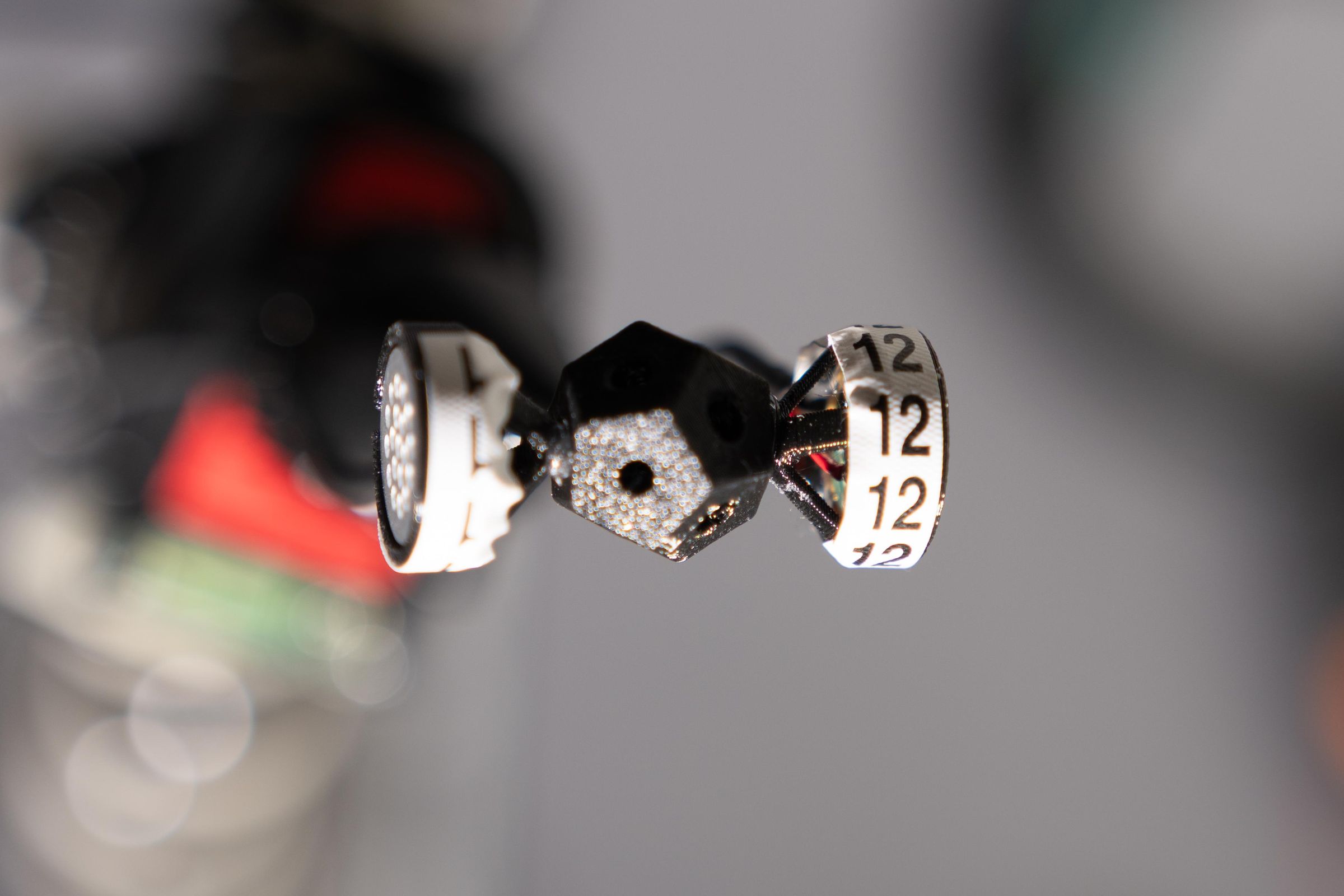
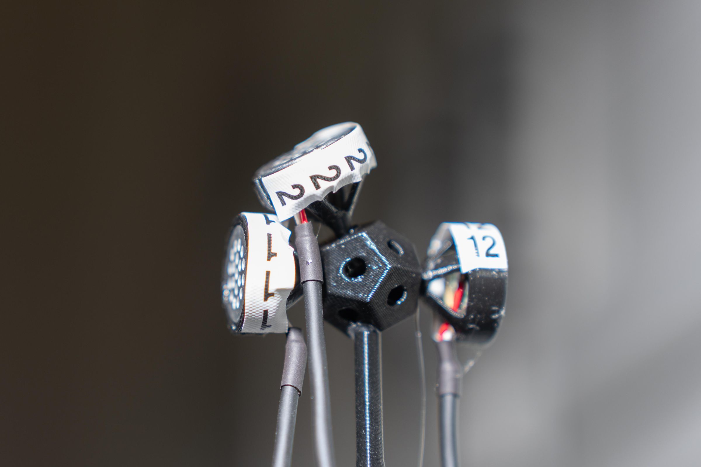
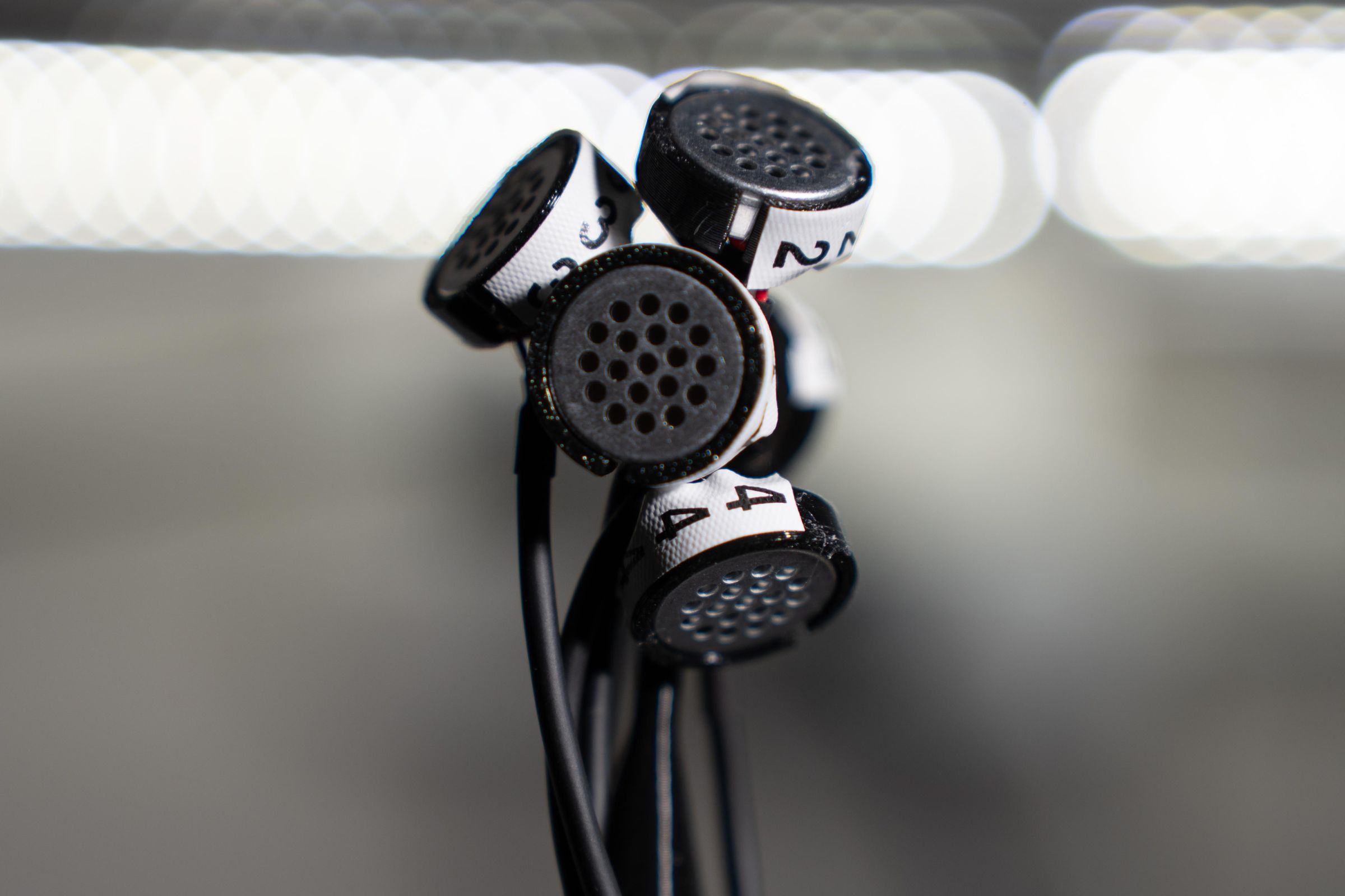
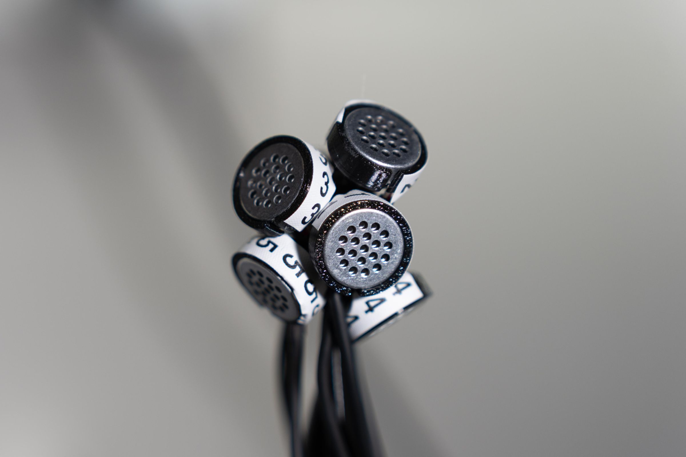
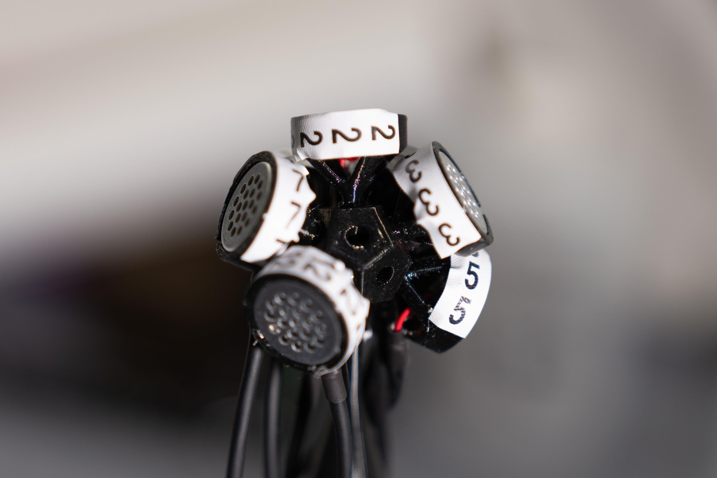
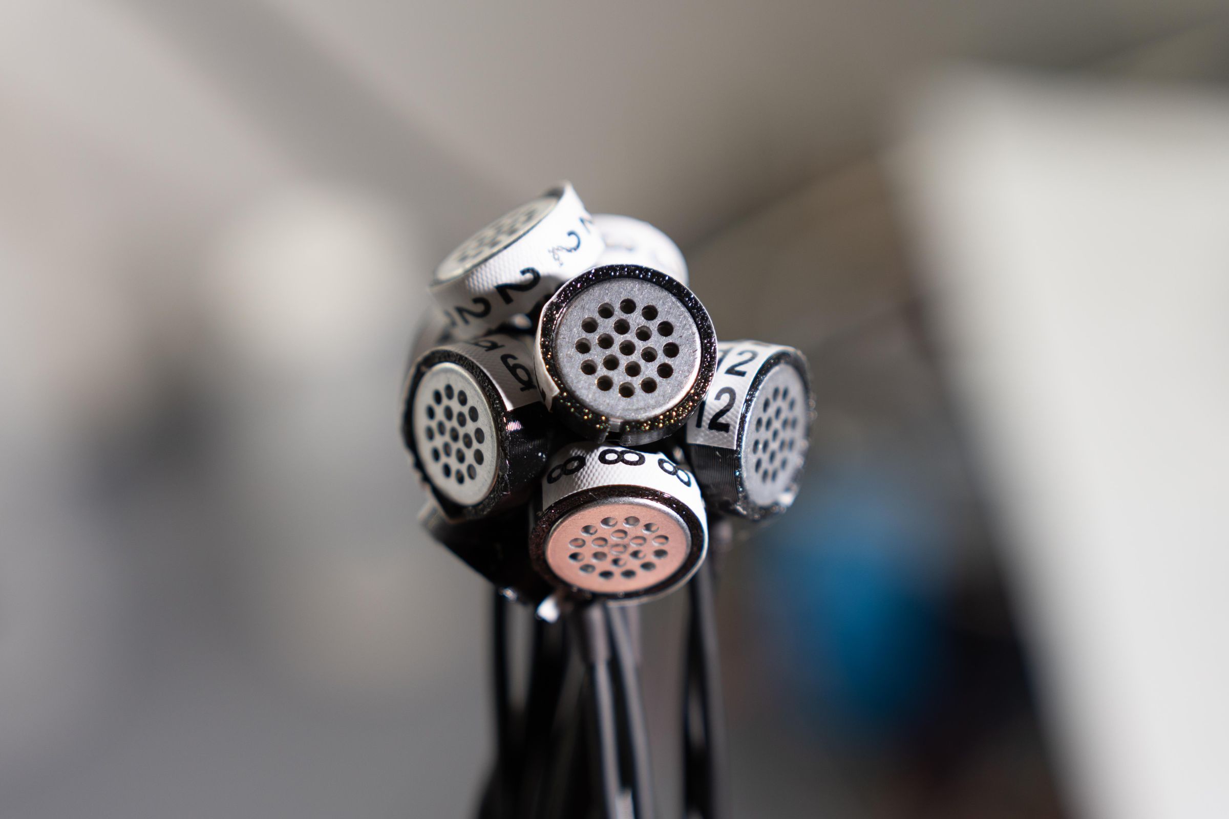
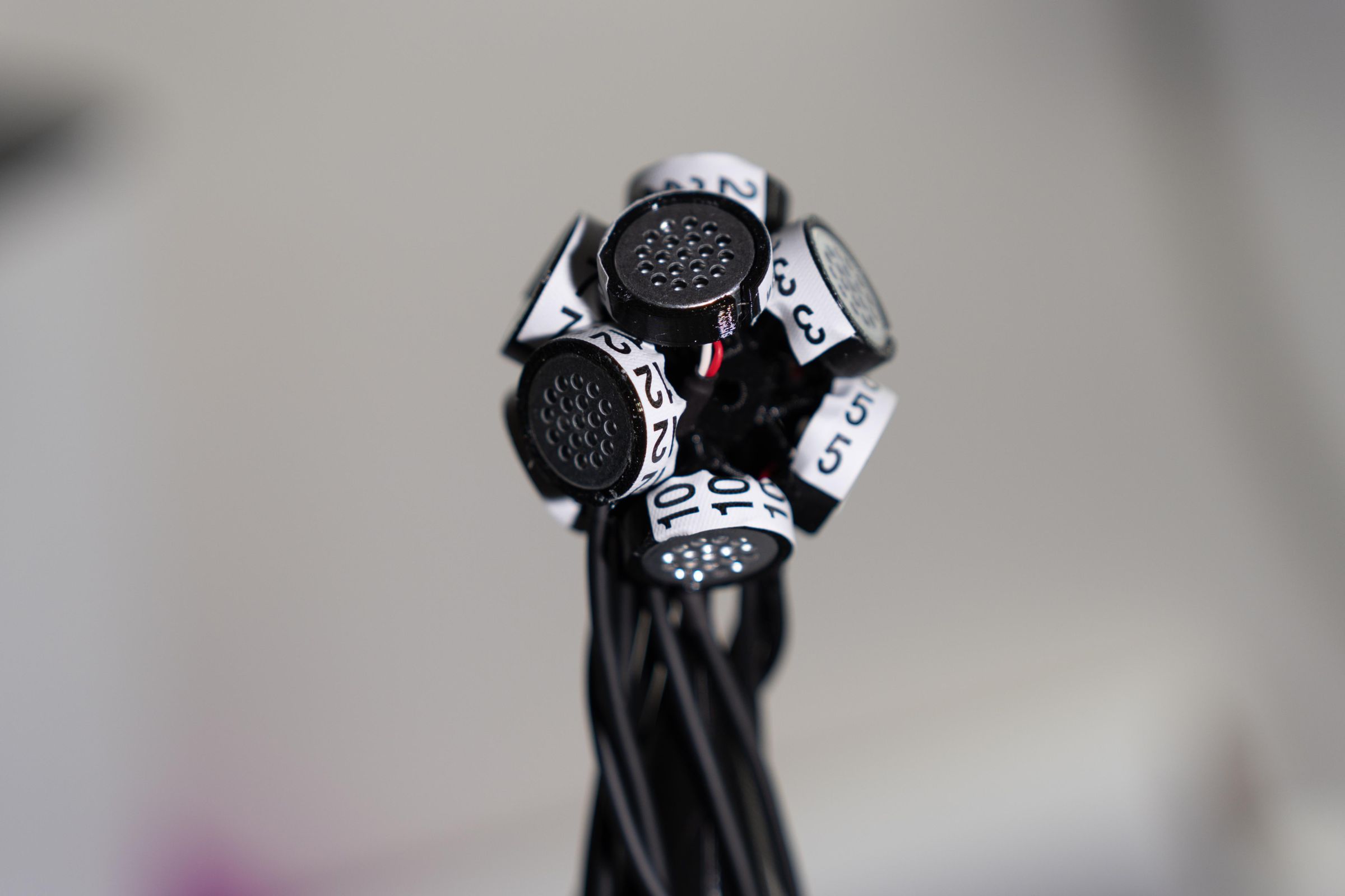
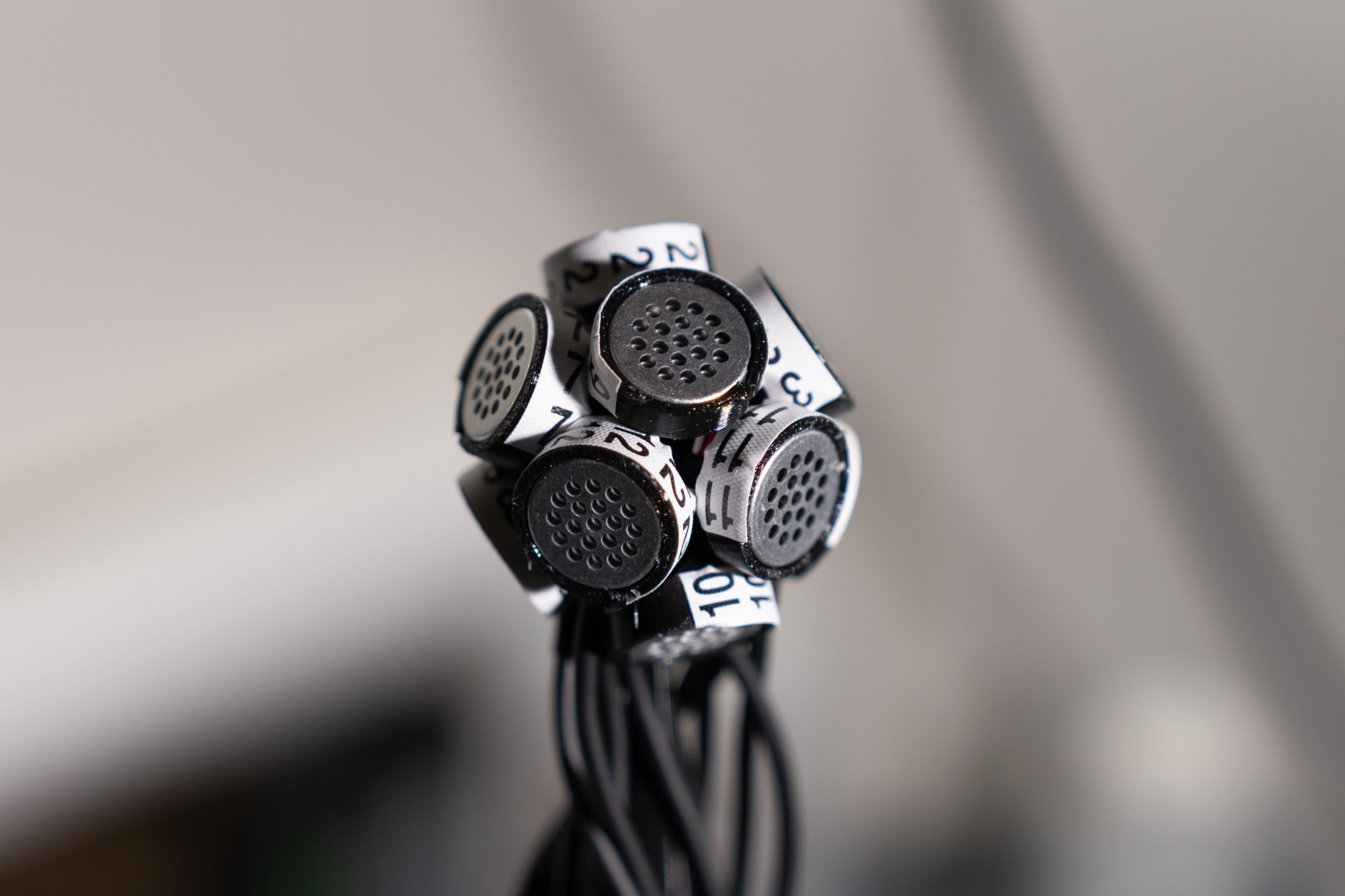
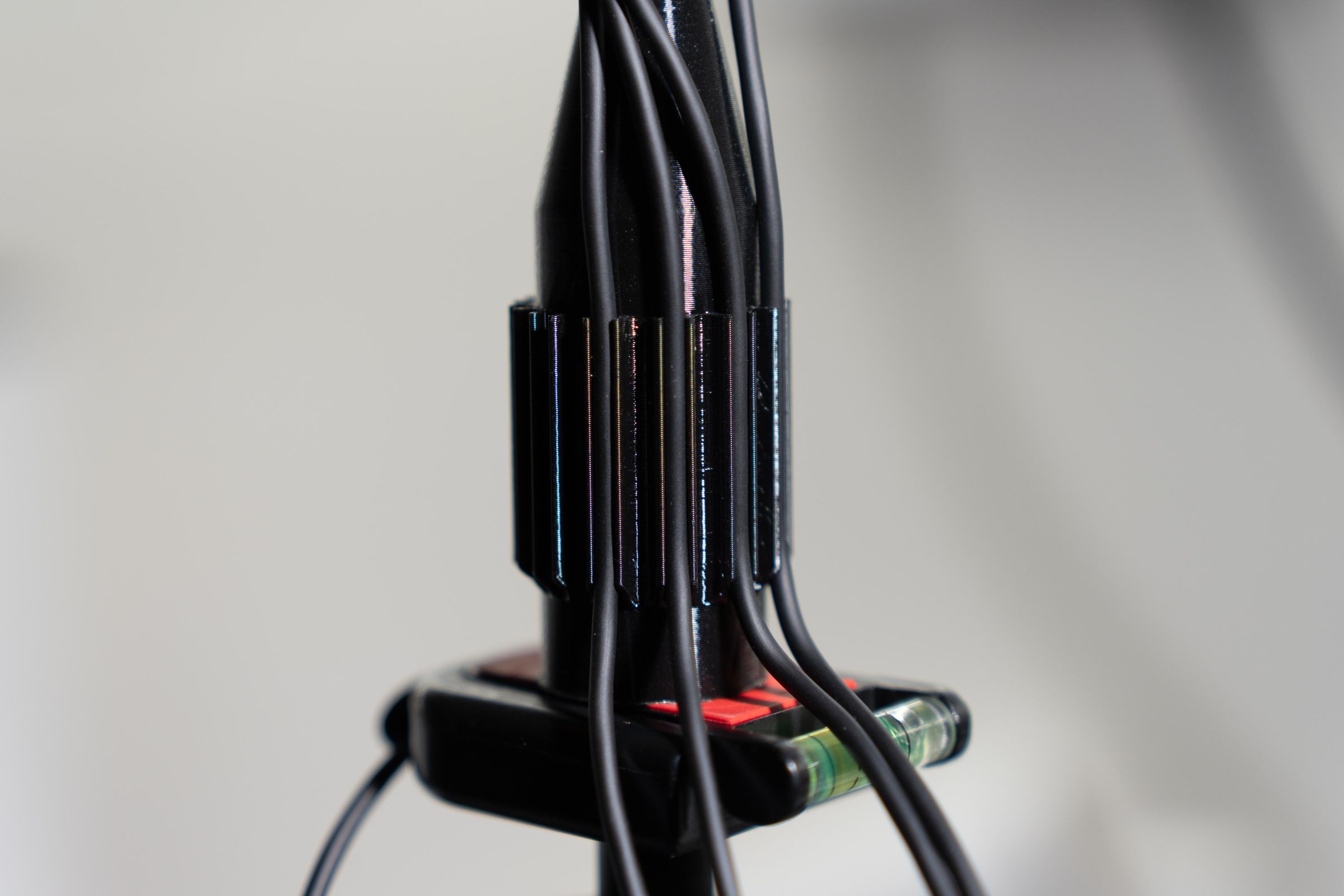
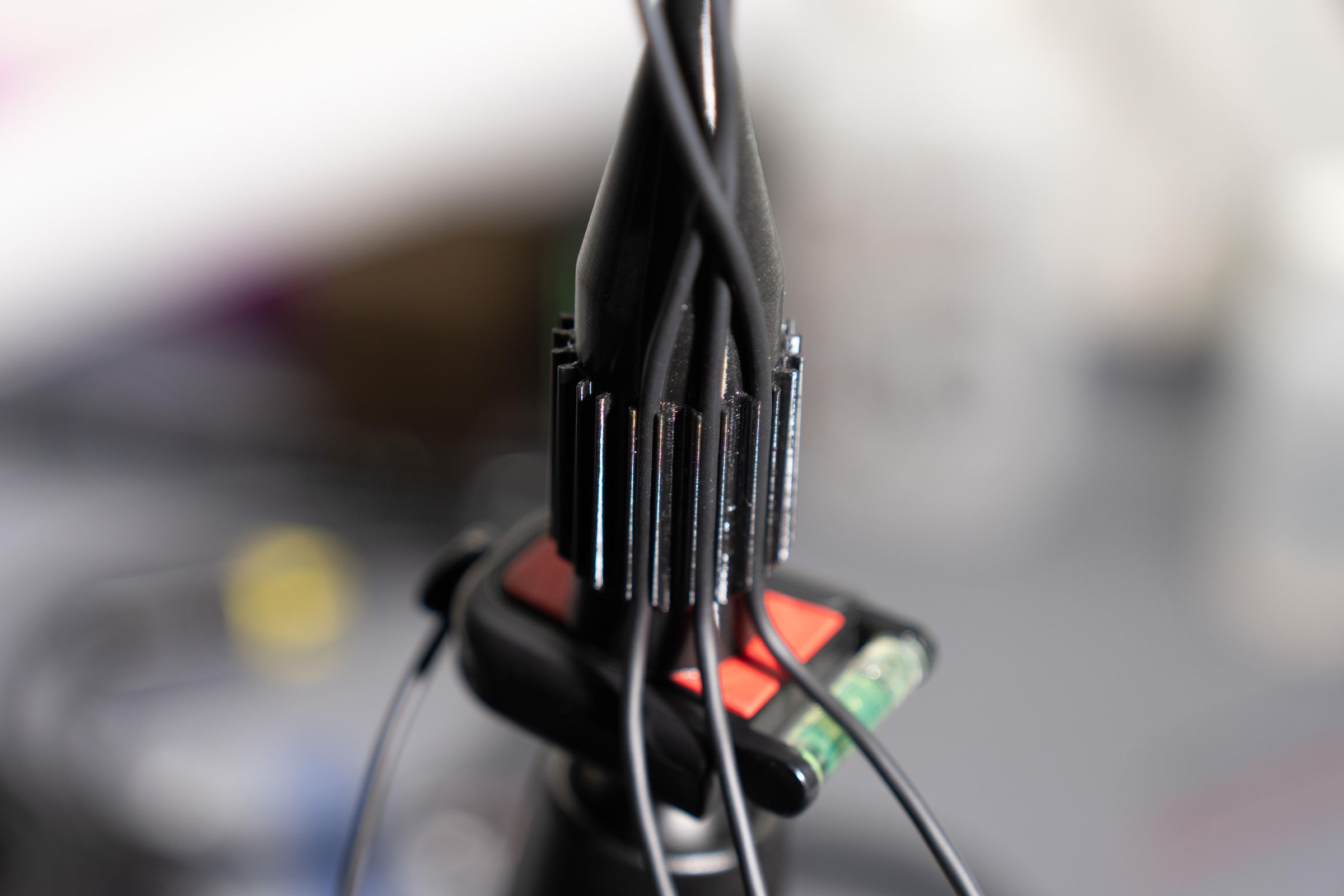
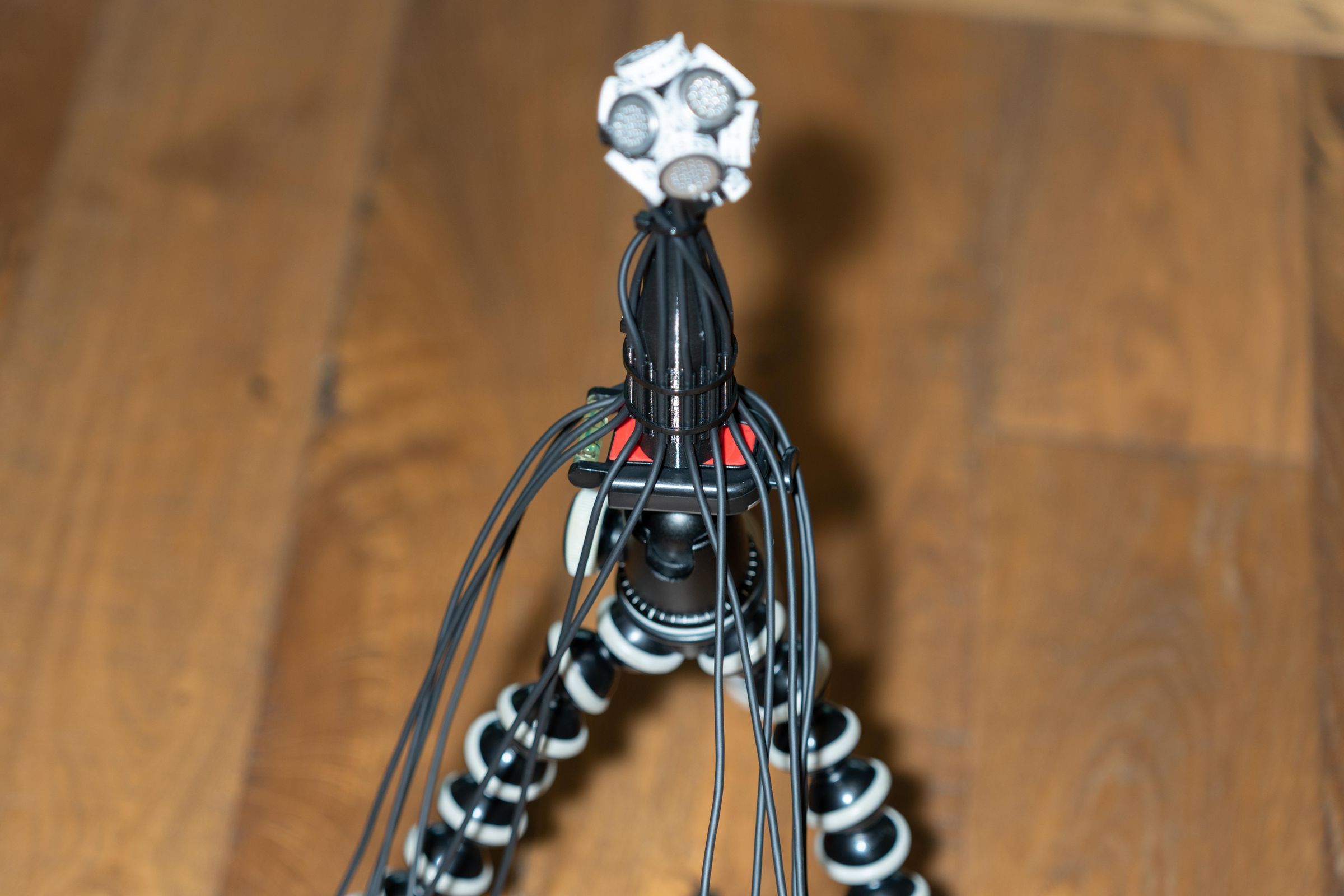
This one goes together very similar to the 8 capsule version except it is tighter for the wiring and easier to get mixed up on capsule locations. Trust me on this one. To make it easier we are using wire labels to label both the capsule and the XLR end. We need this also for the four XLR connectors that are white. The wire bundle is bigger as well after it gets put together. One final difference is that the geometry piece doesn't have a “front locator” In its place Capsule #1 faces forward. This one of the few Ambisonic Mics that I know of that has a forward facing capsule. I printed a different colored capsule holder for Capsule one on one of my builds.
Mount the Geometry piece to the Mic Body. The mounting hole is on one of the faces. There are two sets of capsule positions that are 180° opposite of each other. One of those will become our “front” and “back” of the microphone.
Apply the wire numbers to the capsule holders. These wire numbers are meant to wrap around a wire and leave a number visible. This makes them perfect to use for identifying the capsules. See the photos for how these look attached.There are four capsules that are using white XLR boots. Those must have a wire number on them. Those are 9, 10, 11, and 12. You can use them on the colored XLR boots for 1-8 as well but it isn't necessary.
Notes
- Azimuth is measured clockwise looking down from above:
- 0° = Front
- +90° = Left
- ±180° = Rear
- -90° (or 270°) = Right
- Elevation is measured from the horizontal plane:
- +90° = Straight up
- 0° = Horizontal
- -90° = Straight down
Downloads
Recording With Them
Let's Use them!
Both of these mics turned out to be really good microphones. Interestingly, It is difficult for me to hear the difference between the JLI capsule and the Primo EM415. That may have to do with the fact both get processed by at least two plugins before you hear them. Or, it could be that both are really good capsules, which is what I surmise. There are audio files of all four variations available for you to compare. Note the sensitivity of the EM415's is higher and at the same gain settings will be louder. Remember that when AB listen testing.
The first step for these is recording. On that front we need to ensure all the preamp gains are identical. I am using ZoomF8nPro’s for this. They allow you to link the trims of the preamps and to set them identically. I also use 32-bit float and 96Khz sample rate. I set them to record a single multi channel Wav file. This makes for an easier workflow. Here are my settings:
- Phantom Power On Voltage for all inputs +48
- Input (Mic)
- Sample Rate 96Khz
- Wav Bit Depth 32-bit Float
- Trim Link: Put all in Group A
- Multi Channel wav file Rec SD-1 and SD-2 Tr1-8(poly)
The Ambi-8 is the easiest to record. Just plug it into a single Zoom (or a MixPre) and go.
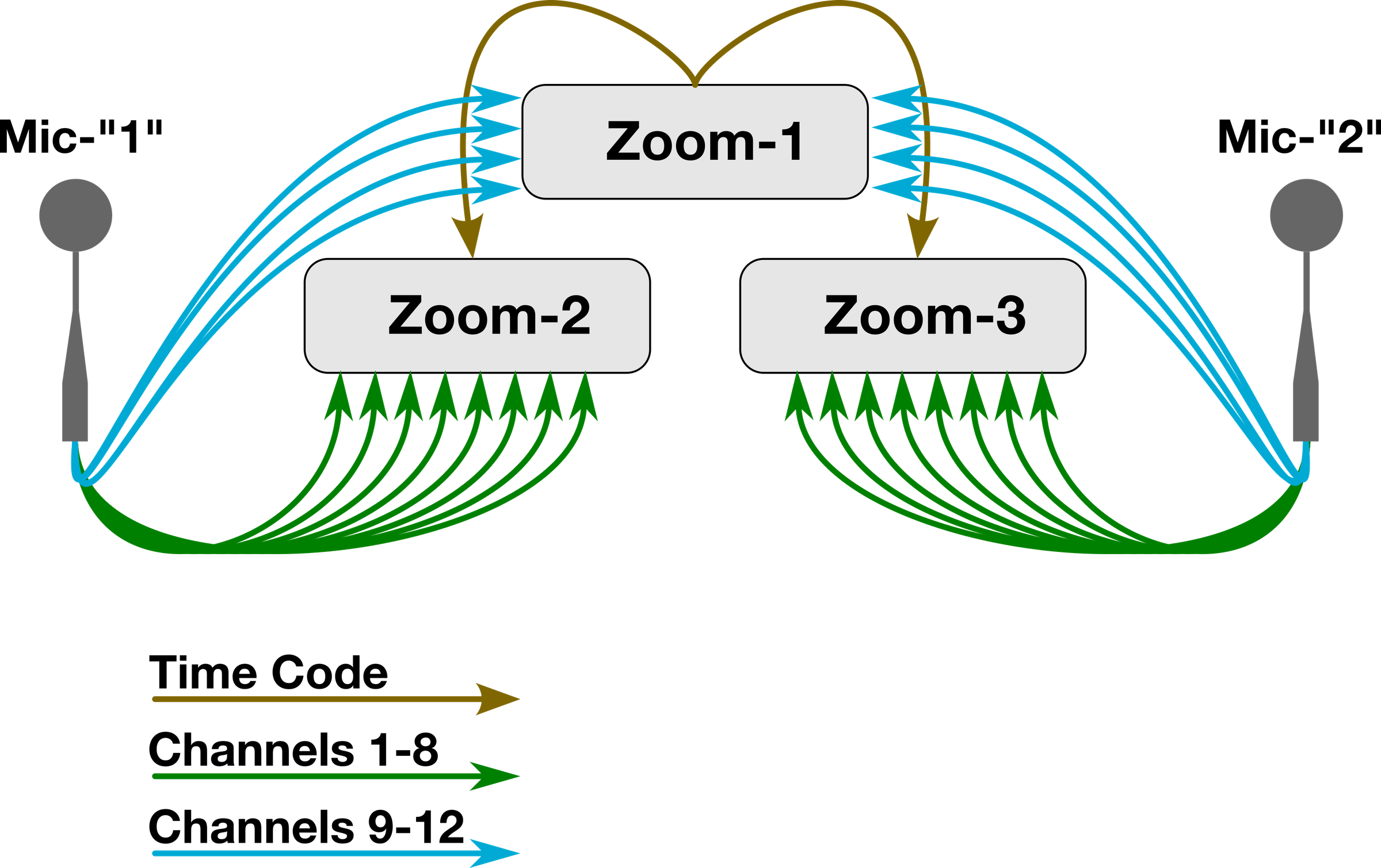
You may have noticed that the Ambi-12 has four more inputs that a single Zoom F8 can provide (or a MixPre). For the Ambi-12 we need to use more than one and ensure they are synchronized. We will synchronize them using Timecode. That is typically for video and film. The Zooms can internally regenerate their clock based on incoming time code. Here is how to set that up:
On the Main unit Under Timecode menu, set it to Mode: Internal Record Run. I set mine to FPS: 29.97D, The key is that all the units use the same FPS. Now on the Syncing units we need to set them to: Mode: Ext Auto Rec (Sync). Then there is one more setting that is crucial. Press Time code again to get to: Ext Audio Clock Sync. That has the Zoom regenerate clock that is synced to incoming time code. Now there is no drift.
The cool part is you can sync multiple recorders. When you press record on the Main unit it starts sending time code. On the synced units, they start recording as soon as they receive it. This works with ZoomF6’s as well.
I did some dual mic recording with both Ambi-12’s and this is the diagram for that setup.
Encoding to "B" Format
Now for the fun part getting them into our DAW and processing all of it. We are using Reaper. To me, this is the most flexible and easiest to use DAW for immersive audio. There is only one plugin we are using that does not come with Reaper. SPARTA. It is actually a suite of plugins, all open source. The main one we need is Array2SH. This is the one that does all the “Mathing” for us. It is an amazing tool with multiple parameters that we need to set up correctly for the best sound. There are multiple concepts going on here that we need to keep track of. It wasn't until I dove into building higher order Ambisonic mics that I really started to grasp what is important and how to best use the tools available for great results. Lets get Reaper setup first then we will adjust Array2SH.
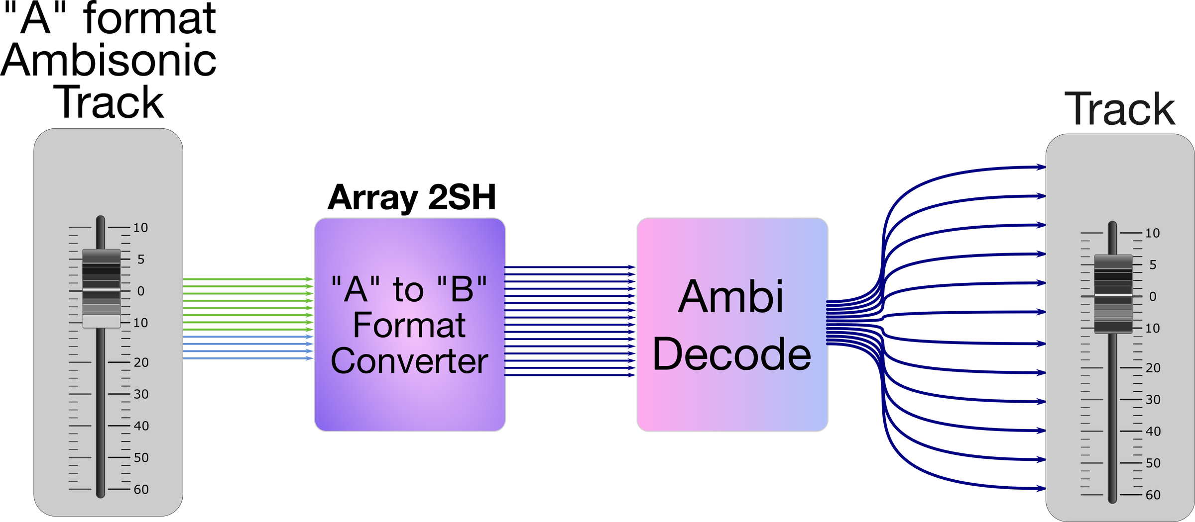
Here is our initial challenge, and is the same for all DAW’s: They were designed from the ground up to be stereo. Reaper is super flexible but all its defaults are for stereo. That means each track has by default two channels. Reaper supports 128 channels per track. We need to set each track to have enough channels available for what we are trying to accomplish. You can have more than are used. The Master Track in reaper is the track that contains the final mix and sends the audio to your audio output hardware. There is a checkbox on all of the tracks for “Send to Master”. We want that deselected for tracks that bring in audio but then route that to other tracks for encoding. This one has bitten me several times ;-). See the video section on reaper setup for this too.
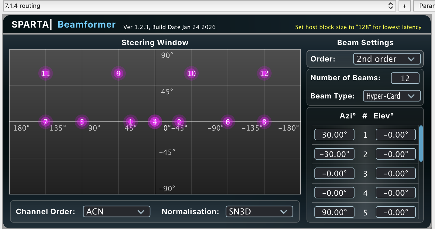
See the diagram for the Ambi-8. The track has to have enough track channels to ensure it covers everything. Here we have our incoming “A” format audio straight out of the microphone. After encoding it is 4 “active” channels for 1st order Ambisonics. Then we go to the Ambisonic decode plugin. This could be a beamformer to multiple speaker outputs. I use this to get 7.1.4 output to my playback system. In this case you need 12 tracks to cover all the outputs.
We can decode to stereo or binaural rendering. In that case there are only two Output channels but we still need to have the higher number to feed into the plugin. In either case, this is the beauty of Ambisonics – it is agnostic to how it is rendered for playback.
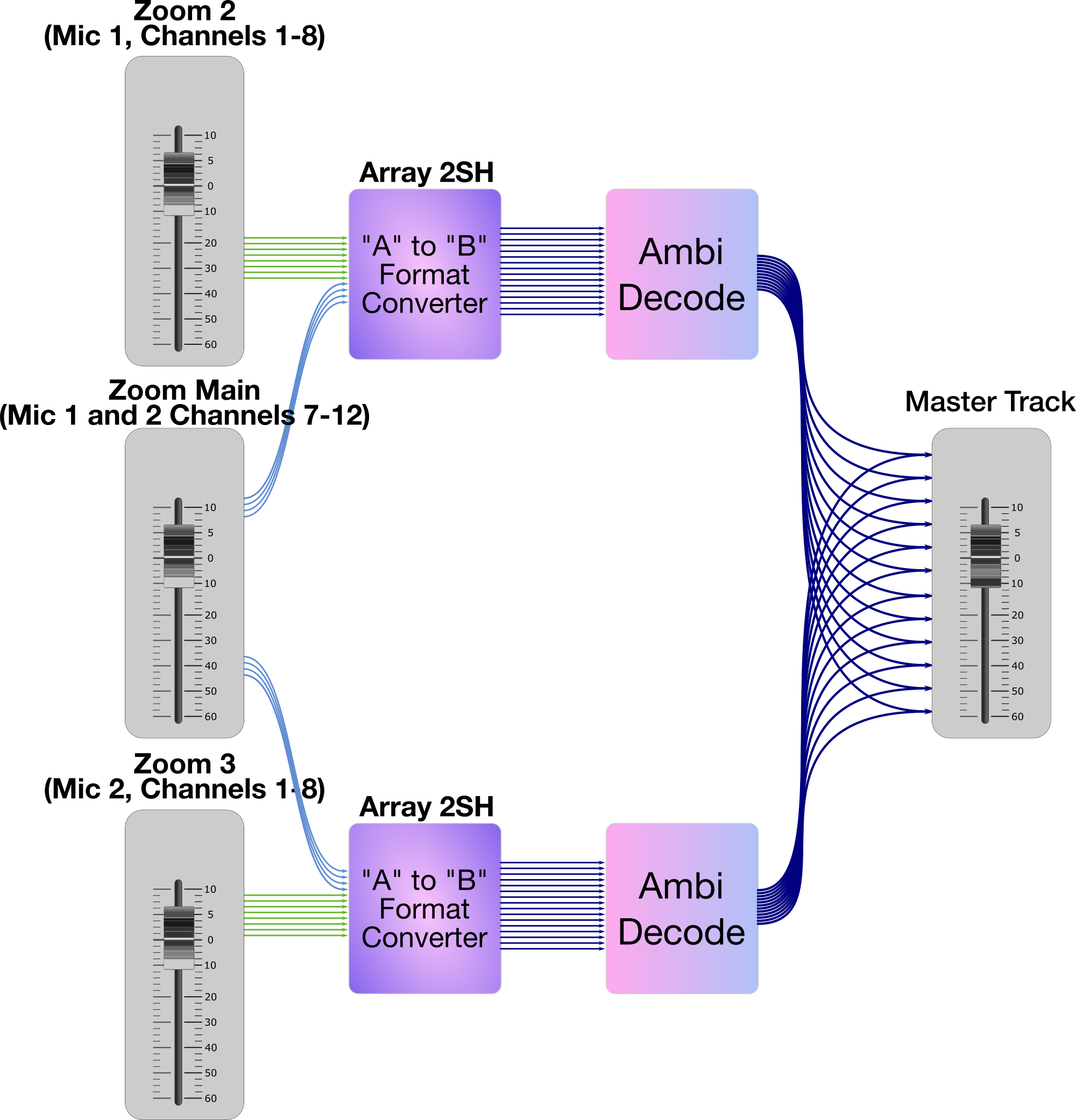
Let's look at my workflow for the recording of two Ambi-12’s
Creating this in Reaper is both easy and confusing at the same time. The video walks you through it. Key points:
- Tracks “Zoom-2” and “Zoom-3” are set to 12 channels.
- Track “Zoom-1” is set to 8 and does not feed the Master Track
- Send channels 1-4 on “Zoom Main” to “Zoom-2” channels 9-12
- Send channels 5-8 on “Zoom Main” to “Zoom-3” channels 9-12
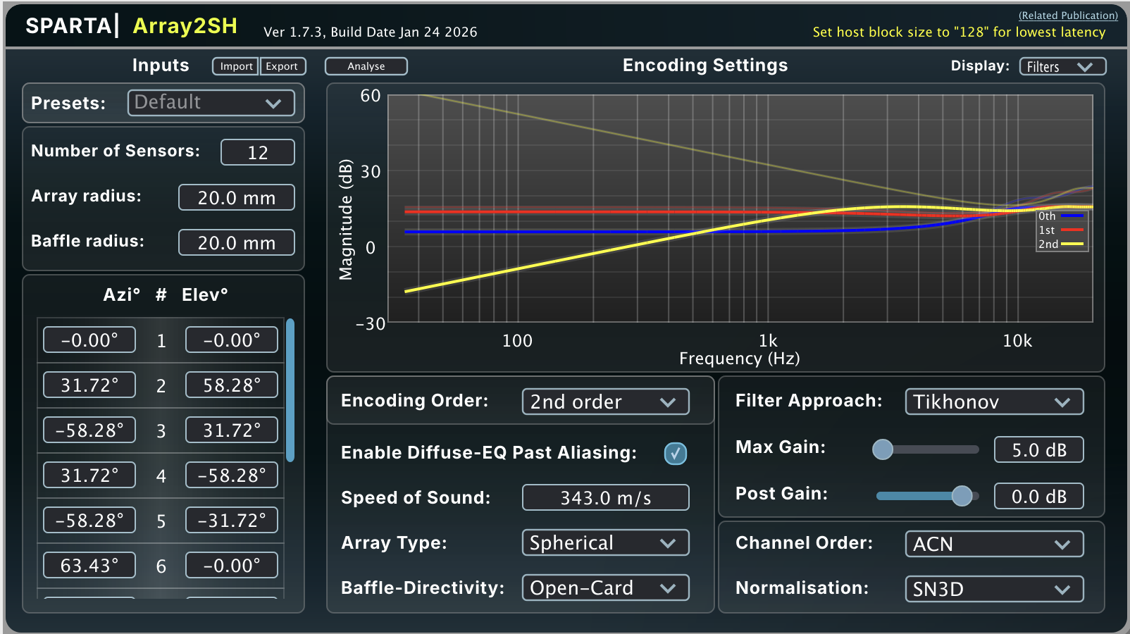
OK now let's look at the Array 2SH settings. This is the brains of what we are doing to get the Ambi-8 and Ambi-12 to become Ambisonic mics. It requires some pretty interesting and complex math. The cool part is the plugin does all the math for us. With that said we need a background on what we are asking it to do. It is taking in sound from 8 or 12 cardioid capsules that point in different directions and mathematically determining the sound field that produced that. A-format describes what the microphones heard. B-format describes the sound field that most likely produced those microphone signals. The more capsules, the more information that Array2SH has to work with. They are in a spherical array meaning they have a common point in space that they are all referenced to with a common radius from the center. That gives us a number to enter. They are “open baffle” meaning the sphere is open, not closed. A closed one would look like a ball. The speed of sound is 343M/sec as we are in air. The number of sensors will be 8 or 12. Output convention is ACN/SN3D That is the standard most Ambisonics use today. That defines our channel ordering and normalization values. We will use this.
Now a couple of controversial topics... Calibration and Ambisonic Order. There is a school of thought that says we need to calibrate an ambisonic microphone. I agree with the premise however implementing it is quite the challenge. Then you need specialized software to implement the specific calibration. I know from modern manufacturing and quality systems that are in place that actual tolerances of as built components are pretty stringent. I also know from 10 years of building microphones that the ones I have built with the same capsules are very close. I am working on a test setup for me to verify this. So then the question becomes “How much error am I introducing if the capsules vary from each other? Remember that 1st order uses 4 channels, 2nd order uses 9 and 3rd order 16 This is the number of channels when encoded into “B” format. It is not the same thing as the number of capsules. I have found through experimentation and listening that Ambi-8 makes a better 1st order mic than my original Ambi-Alice with four capsules. And that the Ambi-12 makes an excellent 2nd order mic. This goes against what the currently available 2nd order mics do. If we look at the math this makes sense. I may have mentioned that we weren't delving too far into the math. I did dive down a rabbit hole on this. Solely from a math perspective, when asking Array2SH to calculate the 2nd order Spherical Harmonics we are asking it to calculate 9 unknowns from 8 pieces of data. That introduces some guess work and a bit of error into some of them. However, when asking Array2SH to create First Order ambisonics from the Ambi-8 and Second Order from the Ambi-12 we are Over Determining the conversion. In essence we are providing extra information to Array 2SH that helps it be more accurate.
One final thing on the Ambi-8 And I designed it this way. The Elevations I am using of +/-45° diverge from the traditional +/-35.26° I wanted more height information. My design is axially symmetric, but not fully geometrically symmetric. Is that “right” or “wrong”? Neither, it is a conscious decision on my part. The ±45° array samples the vertical first-order component 6dB higher than either horizontal component. For an eight-capsule array with four capsules above and four below the horizontal plane, the ±35.26° angle makes the average sensitivity to the X, Y, and Z first-order spherical-harmonic components equal. With all of that said, Array2SH takes into account the angles used as part of its encoding algorithm. For those who want to build the traditional 8 capsule mic I have included a geometry piece and body to mount it to in this step of the instructable. Instead of inserting the base into the geometry piece, you glue them together. Please reach out in the comments on this if you have thoughts one way or another.
Array2SH
Lets go through each menu and look at it. Lets start with Inputs. Presets: included are ones for commercial microphones. Next to it are Import and Export. That lets us bring in or export out a JSON file that includes all the settings. I have created those for the Ambi-8 and Ambi-12. There is a final tweak or two to put in depending on your actual build. Number of Sensors is the actual number of mic capsules we have. Next up are Array Radius and Baffle Radius. Array Radius is the Radius of the actual build. How far are the capsule diaphragms from the theoretical center of the array? In our case that is 20mm. We are going to tweak that a bit. For the Ambi 8 and 12 with the EM415’s it is 18mm. Measure yours as built. The EM415 diaphragm sits about 1mm in from the edge. The JLI16mm about 1.5mm. My as builts show that the spacing on the JLI Ambi builds gives me the 20mm radius and 18mm for the EM415’s. The Baffle Radius is only applicable to solid surface ambisonic mics like the EigenMike. The final settings for inputs are the actual Azimuth and Elevation. That is taken care of in our JSON file.
Now onto the Encoding Settings. Encoding Order is the Ambisonic Order. The other simple to set ones are Speed of sound, Array Type, Baffle-Directivity, Channel Order and Normalization. Our array is spherical our mics are Open-Card and we are using ACN channel order and SN3D normalization. EQ Past Aliasing, Tikhonov regularization, and maximum EQ gain are the ones we need to play around with…
When EQ past Aliasing is checked, Array2SH continues applying the radial EQ above the estimated aliasing frequency. This can give a flatter magnitude response, but may increase high-frequency artifacts, noise, coloration, and directional errors. Play with this one and listen to it both checked and unchecked. This tries to keep the high-frequency spectrum useful even though it is no longer spatially correct. Without it we lose some of the high frequency sound that we expect to hear but it may not be spatially accurate. For our array radius we are looking at about 5.5Khz as the crossover frequency.
The next two: Tikhonov regularization, and maximum EQ gain are directly linked. Tikhonov regularization prevents the encoder from applying excessive gain when trying to correct parts of the microphone array’s response that are weak or poorly determined. It trades a small amount of theoretical accuracy for a more stable, lower-noise, and often more natural-sounding result. Listen to this as you adjust the gain. Also look at the EQ graphs that it changes. I find 10dB is my go to for both of these. You can hear the response chage when you change this. It sounds like a mid band EQ boost with too much gain.
The tradeoff is basically:
- Lower max gain: less correction, less noise/tonal change, potentially slightly less spatial accuracy.
- Higher max gain: stronger correction, but more coloration and greater amplification of weak/noisy modes.
Play with this a bit and listen to how the sound changes along with the spatial accuracy.
Array2SH provides several methods for limiting the gain of the radial equalization filters. Tikhonov regularization was used for these microphones because it provides a smooth, mathematically well-behaved inverse while preventing excessive amplification of weak array modes. In listening tests, relatively low (10dBish) maximum EQ-gain settings produced the most natural tonal balance. My two cents…
Mixing and Playback
Now we get to actually listen to what we recorded.
Decoding B format
Now we have our ambisonic B format signal. What can we do with it? A lot actually. In fact, answering that could take much more time than we have here. We are going to look at two specific SPARTA plugins. We will get those set up and working then I will leave it to you to explore.
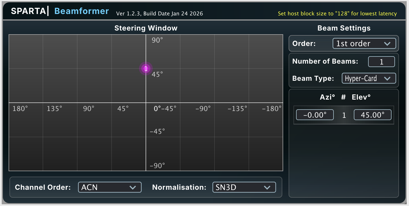
Our first plugin is the SPARTA Beam Former. This one allows you to create a beam of sound pointing in whatever direction you like. We can create two beams facing left and right at +/-55° for a simulated ORTF. We can create four beams for Quadraphonic or my go to: 12 beams for 7.1.4. The controls for the number of beams and their Azimuth and elevation is pretty straight forward. Set ACN and SN3D (should be this by default). You need to select the same order fro AMbisonics as the signal. 1st for the Ambi-8 and 2nd for Ambi-12. There are three choices for beam type. Cardioid and Hyper Cardioid should be familiar. The Third choice is “Max EV”. MaxEV means Maximum Energy Vector. Instead of “make this mathematically resemble a cardioid,” it chooses the order weights to maximize the concentration of reproduced acoustic energy in the steering direction. Once again, play with these as you listen. For first order, there really isn't enough information to go beyond Cardioid so I leave it at that. For Second Order and above, I prefer Cardioid or Hyper Cardioid depending on the source material.
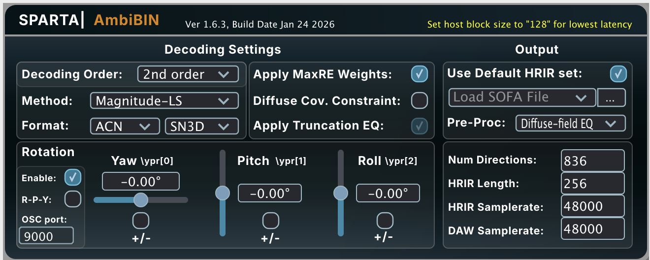
The next plugin is SPARTA AmbiBIN or one of their Binaurilizer plugins. There are others and IEM also makes great open source plugins. Let's explore this one and then I will turn it over to you to explore. SPARTA AmbiBIN converts the B-format recording to two-channel binaural audio for headphone listening. Set the Ambisonic order to match the recording and use ACN/SN3D channel formatting. I use the Mag-LS decoder, which provides improved high-frequency binaural reproduction by prioritizing the magnitude of the HRTF when the spatial resolution of the Ambisonic signal is insufficient to reproduce the complete HRTF. OK… What is an HRTF? In a nut shell, it is a head related transfer function. A what?... Head-Related Transfer Function (HRTF) describes how sound arriving from different directions is changed by your head, ears, and outer ear before reaching your eardrums. These small differences in level, arrival time, and frequency response are some of the cues your brain uses to determine where a sound is coming from—including whether it is above, below, in front, or behind you. Our brain also uses a lot of other cues but acoustically the HRTF describes what our head and ear shape do to sound before it gets to our rear drums to be sent to the brain. The closer we can match that, the better binaural sound works. Along with the setting we have applied, AmbiBIN lets us import these files. Getting one that exactly matches you is possible. There is a database of ones you can experiment with. Please experiment with these. One other thing that this plugin lets you do is to rotate the sound field. Both with sliders and with actual headtracking. Headtracking is in itself a separate instructable so I am only going to mention that you can. If you have a mac and apple airpods that support it, google this and it will walk you through it. It is quite amazing.
Real world and advanced uses
OK, here is where the fun comes in. A single ambisonic mic captures sound at a single point in space. We have a lot of information on the sound field but what we don't have are timing cues from the spacing of our ears. Or the timing cues of a pair of microphones spaced apart. There are a few things we can do here. We can add artificial delays and create a fake sound field. We can add in other microphones or use an Ambisonic mic as one part of a recording session. Both work great.
The first one is a variation of creating a fake stereo by adding some delay to a mono signal and panning them differently. Let's go back to the ORTF creation mentioned above. True ORTF has two microphones facing +/-55° left and right while being spaced 17cm apart. That 17cm corresponds to a time difference of about 500uSec. Start by duplicating the track with the B format audio on it. Beamform the first it to a Cardioid that points 55° to the left. On the second track create one that points 55° to the right. Now add a delay and set it to .5mSec. ReaDelay lets you do that. Listen with headphones and AB it. Feel free to play with the delay time as well. You can do the same thing with 7.1.4. Beamform all the left side on track one, Beamform track two to the right side. This case will be a little different. ReaDelay is only two channels. But what we can do is add in a Media Playback offset and add in a small delay to one side.
On the track you want to delay:
- Click the track’s ROUTE button in the Track Control Panel.
- In the routing window, look for Media playback offset.
- Check/enable it.
- Enter the offset value. I would start with .5-3ms and listen to what happens to the sound field.
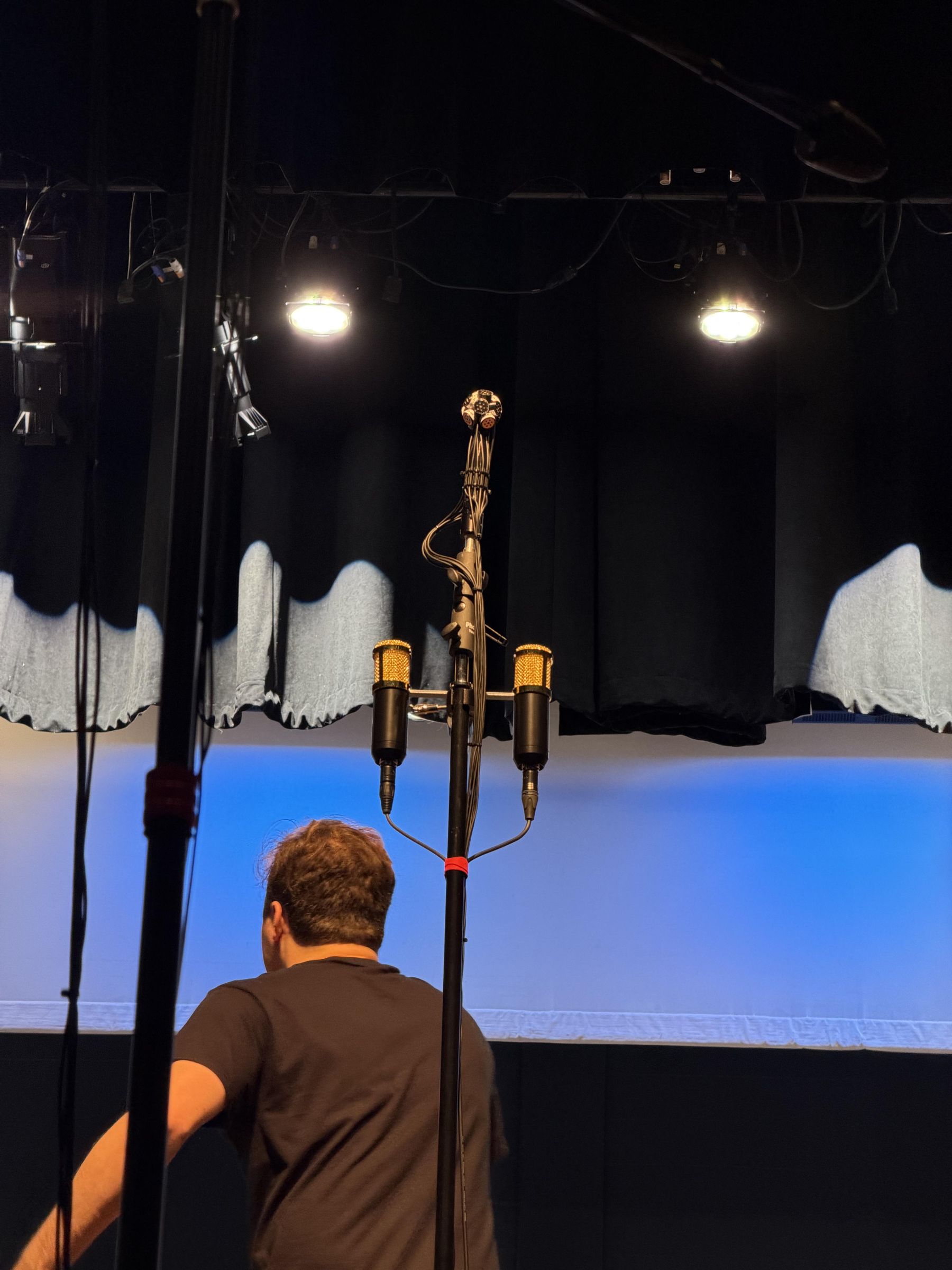
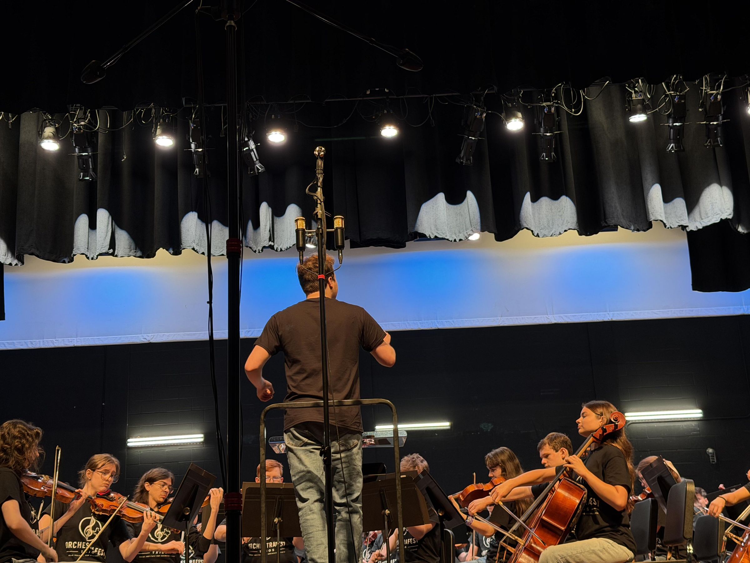
Using an ambisonic mic as part of a larger setup lets you do several cool things. They are one more tool in your kit for capturing the world around you. As a center mic for a choir or orchestra they let you steer things around in post. With two of them you can record what would be a typical AB setup with them 2M apart but then in post spread them out to multiple speakers in an immersive playback system. I am including two recent recordings I did with them to let you hear for yourself. All the raw audio is included so you can bring it into Reaper or any DAW and experiment.
The first is a performance of Jean Sibelius, Symphony #2. This was performed as part of the Texas Orchestra Institute’s summer concert. That is an amazing summer program that has over a 100 students on stage. I had the ability to set up a couple microphone setups which included an Ambi-12 centered in an ORTF Pair. There were two outriggers as well. The second recording is a Pipe Organ that I am lucky enough to live close to. There are two performances of Bach. One has two Ambi-12’s and one two Ambi-8’s both have an ORTF pairs and two side mics. All the additional microphones are my OPA based Serena with a TSC-1 capsule. The Reaper session is set up with those so you can solo or mute them. The Ambi-12 used has the JLI 16mm cardioid capsules. The venue had an excellent noise floor.
The second set of recordings is a pipe organ playing Bach. There are two separate performances as I couldn't record all four ambisonic mics at once! I have two reaper sessions, one with the Ambi-12’s and one with the Ambi-8’s. This venue is at a local Lutheran church which was gracious enough to let me record there. Their HVAC system was fully operational while I was there so the noise floor is not on par with the Orchestra. With that said, the organ was loud which really helped the S/N ratio.
Summary
Summary
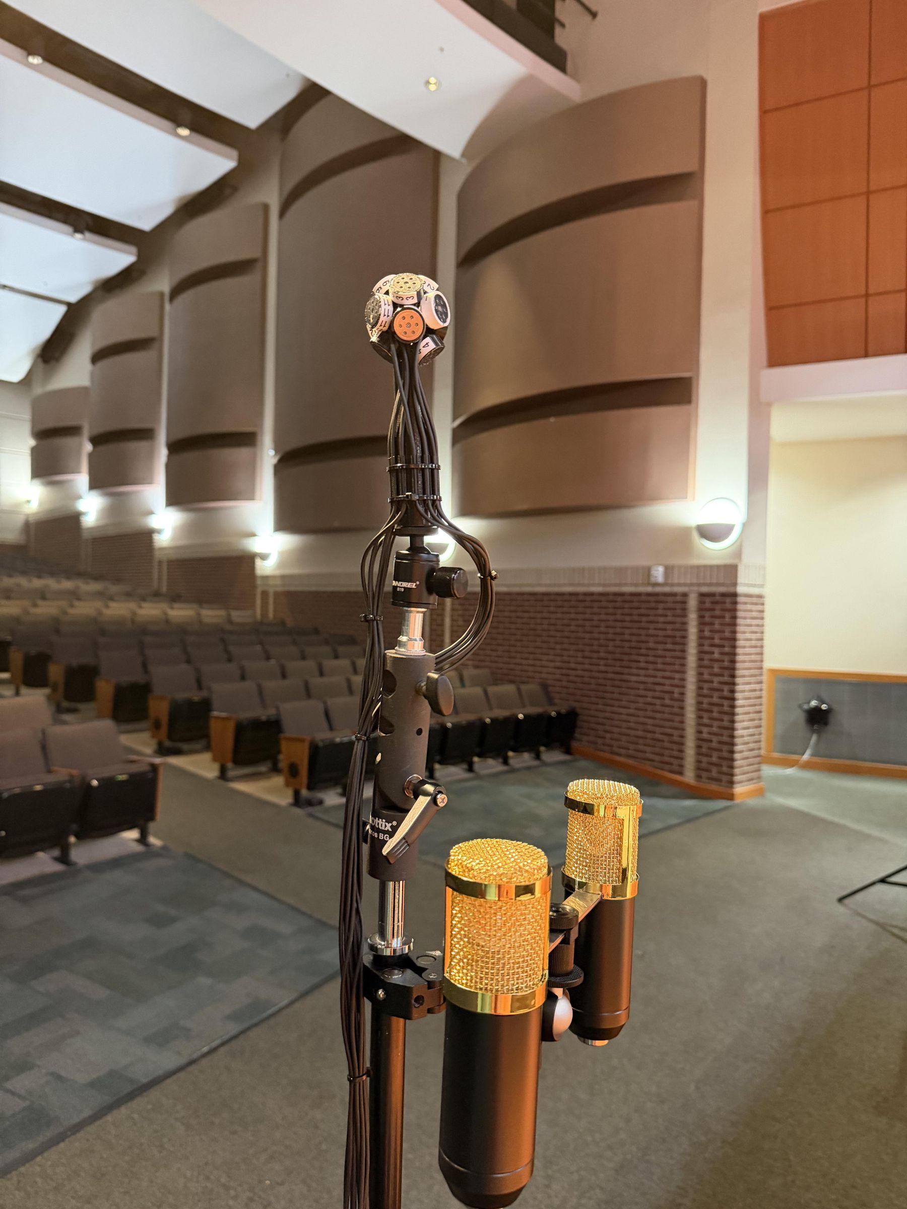
Both of these builds provide excellent real world ambisonic mics that perform better than four capsule FOA mics. The Ambi-8 with my +/-45° elevations provides the increased height detail I was hoping for. Initially I tried to force it to encode into 2nd order ambisonics and was disappointed with the results. However when I went back to 1st order encoding I was impressed. I am pretty sure I am the first person to change the angle of elevation in an attempt to improve height information.
I am really blown away with how well the 12 capsule mic performed. This layout has been proposed a few times in the literature. I am not aware of anyone else that has built one. It can be traced to Gerzon who was apparently thinking about a 12-capsule, nine-channel second-order microphone more than 50 years ago. My implementation is very different—modern DSP, Array2SH, 3D printing, cardioid capsules, etc.—but the basic question of how to get nine second-order components from a compact 12-capsule array goes right back to the beginnings of Ambisonics. All hail Gerzon! If you have built one or know of it please leave a comment or reach out to me directly.
This was also an experiment in capsule selection, which I have not commented on yet. I honestly don't hear a difference between the two. There is a sensitivity difference that shows up. The EM415 has a higher sensitivity. It also has a better published spec for S/N ratio which directly relates to its self noise. The JLI has a better published frequency response graph. There is some truth to these and some marketing. Both capsule specs are based on how they show the capsule being connected. We are improving on that with how we are wiring them.
The sound quality here really depends on how you encode and decode them as well. Let me know which one you think is best. I hope you enjoy this one, there was a lot of work that went into it. Enjoy! Here is the Audio