Design and Implementation of an Autonomous Solar-Powered IoT Smart Greenhouse Using Edge Computing and Full-Stack Technologies
by ΒαγγέληςΑ1 in Circuits > Arduino
568 Views, 3 Favorites, 0 Comments
Design and Implementation of an Autonomous Solar-Powered IoT Smart Greenhouse Using Edge Computing and Full-Stack Technologies


Introduction
The increasing global demand for food production, combined with the effects of climate change and the need for efficient resource management, has led to the development of innovative technological solutions in the agricultural sector. Traditional greenhouse management methods often rely on manual monitoring and intervention, which may result in inefficient use of water, energy, and labor resources.
The emergence of the Internet of Things (IoT) has introduced new possibilities for smart agriculture by enabling continuous monitoring, data collection, and automated decision-making processes. Through the integration of sensors, microcontrollers, communication protocols, and cloud technologies, it is possible to create intelligent systems capable of maintaining optimal environmental conditions for plant growth while minimizing human intervention.
This work presents the design and implementation of an IoT-based Smart Automated Greenhouse System. The proposed system continuously monitors critical environmental parameters such as air temperature, air humidity, and soil moisture using multiple sensors installed inside the greenhouse. Based on the collected data, automated actions can be performed, including the activation of irrigation systems, ventilation mechanisms, and heating devices, aiming to maintain ideal cultivation conditions.
The hardware infrastructure of the system is based on Arduino Uno and ESP8266 (Wemos D1) microcontrollers, which are responsible for sensor data acquisition and communication. The communication between devices and services is achieved through the MQTT protocol, providing lightweight and efficient message exchange suitable for IoT environments.
To support scalability and ease of deployment, the entire software infrastructure is hosted on a Raspberry Pi platform using Docker containerization technology. The system consists of several interconnected containers, including:
- A Spring Boot backend application responsible for business logic, data processing, and REST API services.
- An Angular-based frontend application that provides real-time visualization of measurements, historical data analysis, and greenhouse management capabilities through an intuitive web dashboard.
- An Eclipse Mosquitto MQTT broker that manages communication between IoT devices and backend services.
- A PostgreSQL database used for persistent storage of sensor measurements, device information, and historical records.
By utilizing Docker containers, the system becomes portable, easily maintainable, and highly extensible, allowing rapid deployment and simplified management of the different software components.
The main objective of this work is to develop a low-cost, scalable, and fully automated smart greenhouse platform capable of improving agricultural productivity, reducing resource consumption, enabling real-time monitoring, and minimizing the need for continuous human supervision.
Supplies
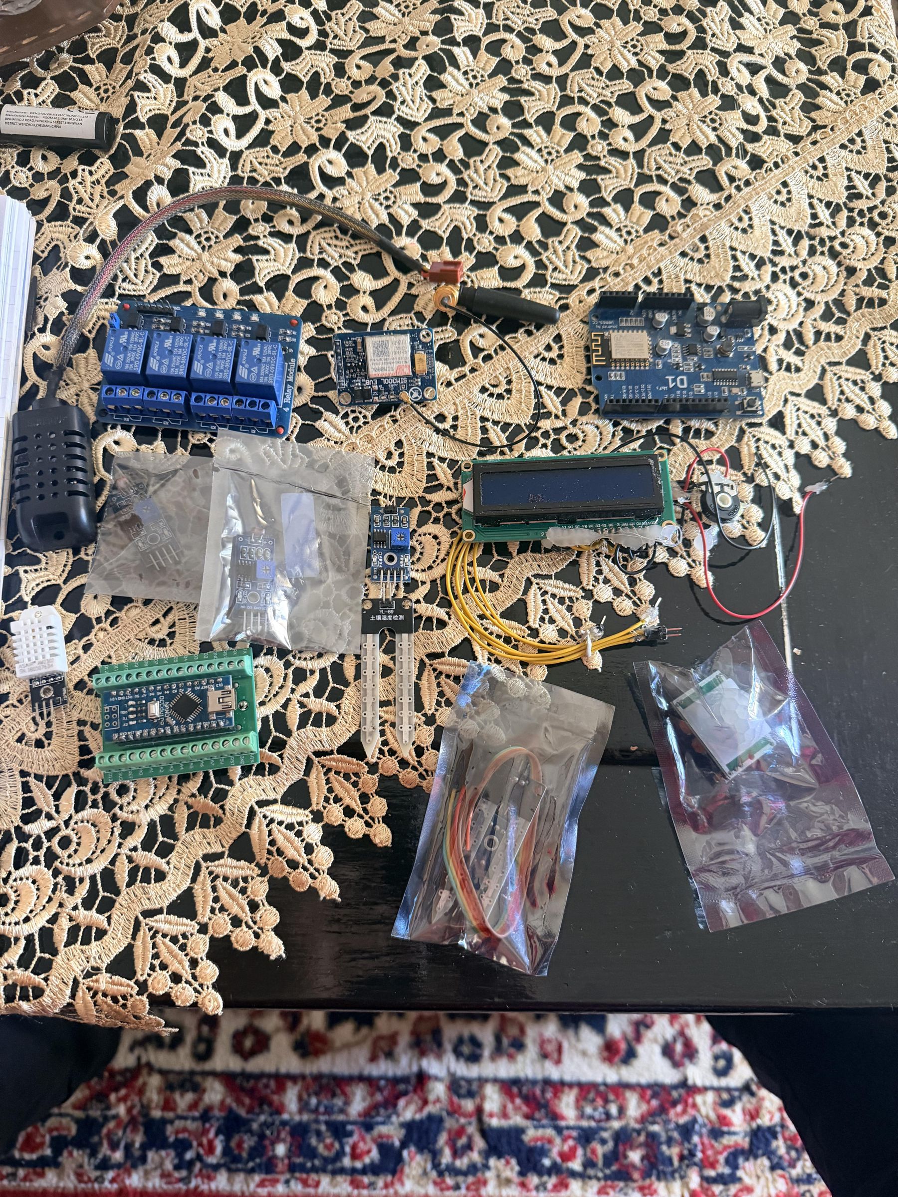
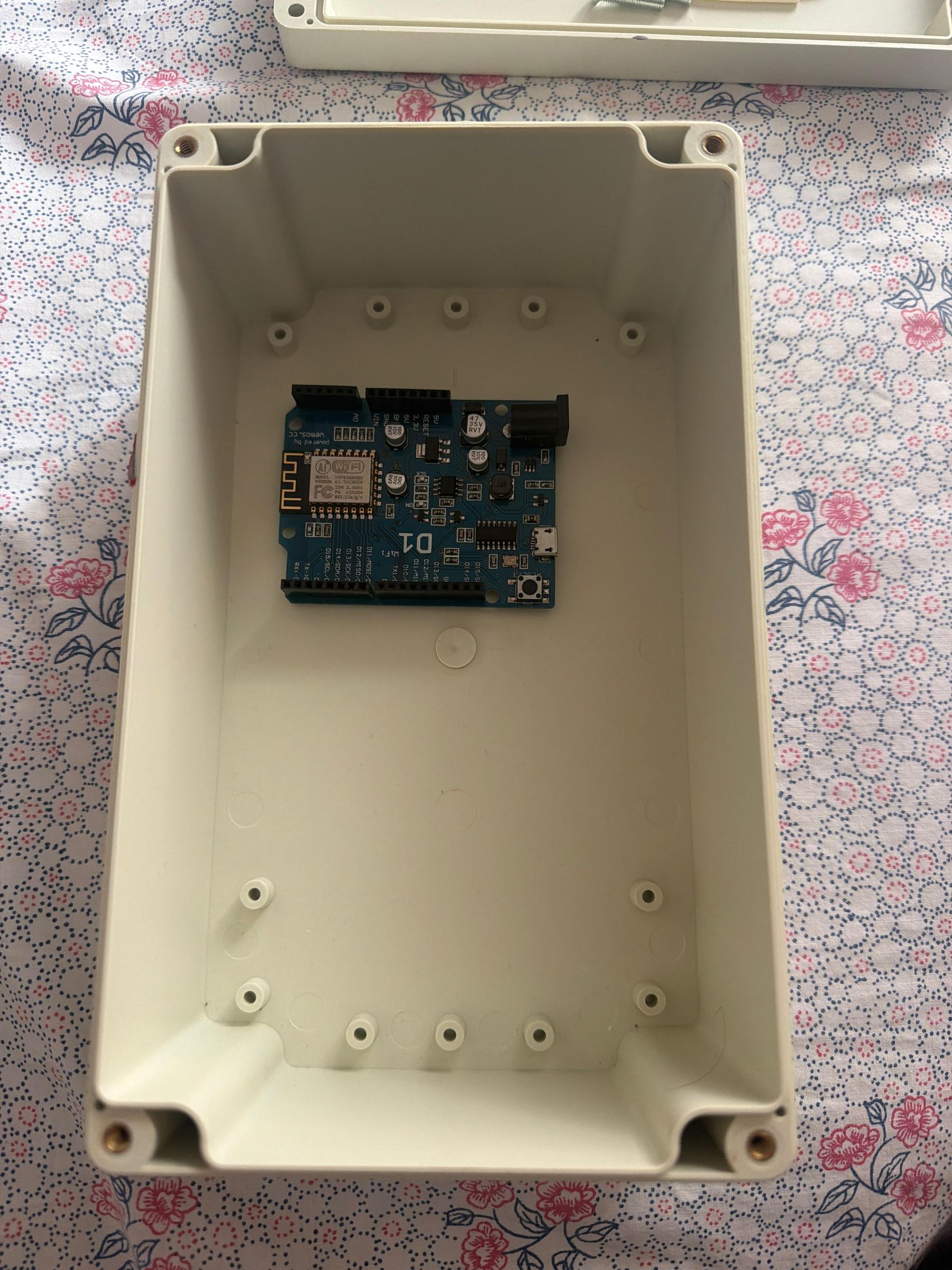
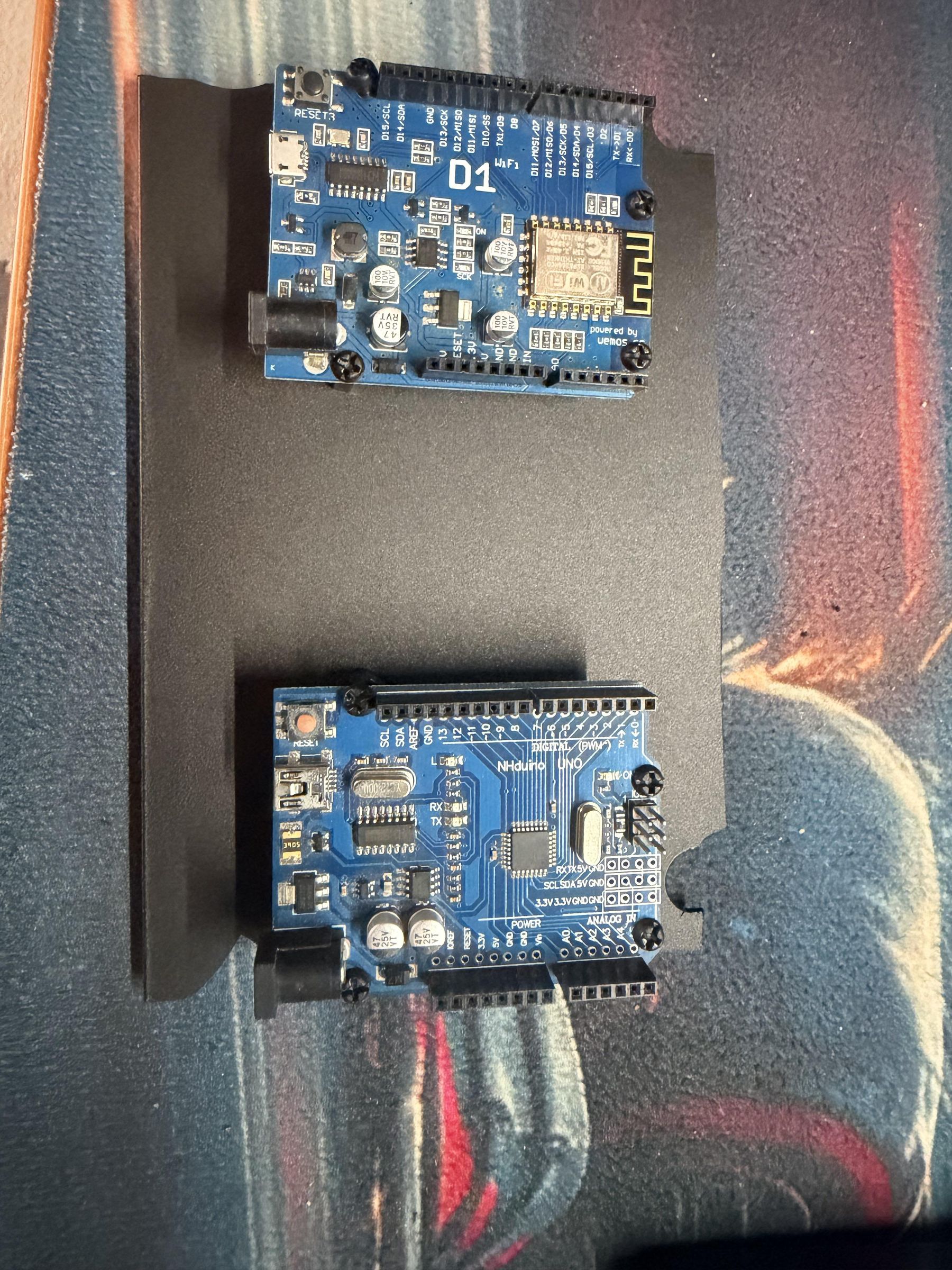
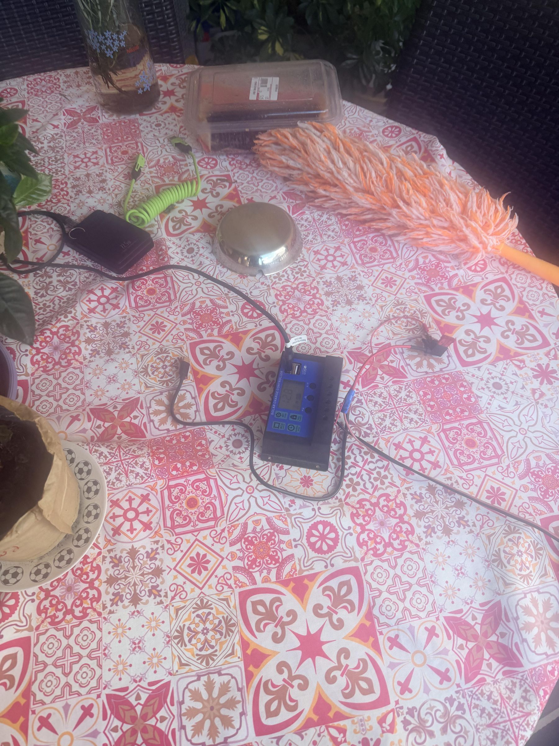
Supplies
The implementation of the proposed Smart Greenhouse System required the use of various hardware and software components. The following materials and technologies were utilized during the development of the system.
Hardware Components
Processing and Control Units
- Raspberry Pi 4 Model B (4GB RAM), used as the main server platform for hosting the software infrastructure.
- Arduino Uno Rev3, responsible for sensor data acquisition, local processing, and control operations.
- Wemos D1 Mini (ESP8266), used for wireless communication and IoT connectivity.
Environmental Monitoring Sensors
- DHT11 Temperature and Humidity Sensor, used for monitoring environmental conditions.
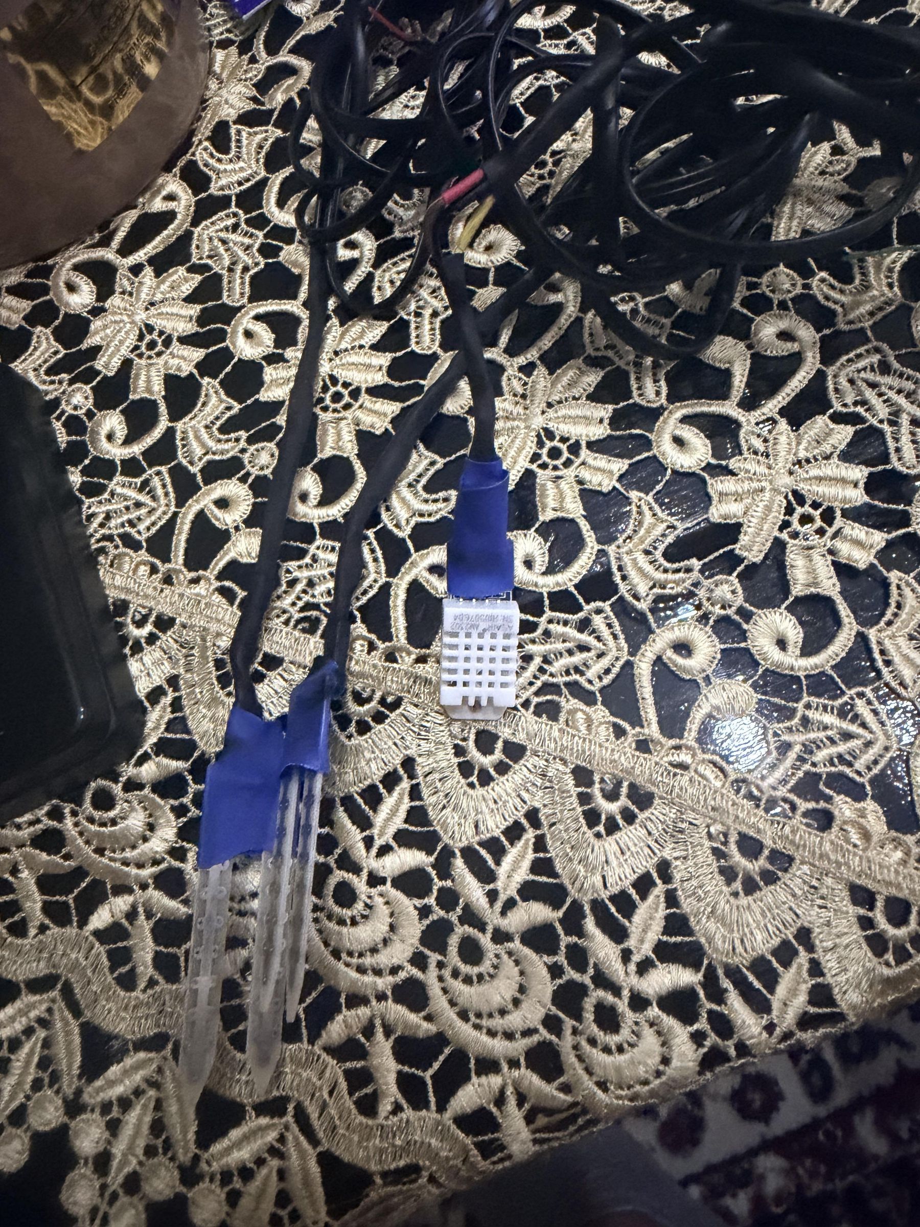
- DHT22 Temperature and Humidity Sensor, initially integrated into the system for improved measurement accuracy. However, the sensor suffered hardware failure during the development phase and is planned to be replaced in a future revision of the system.
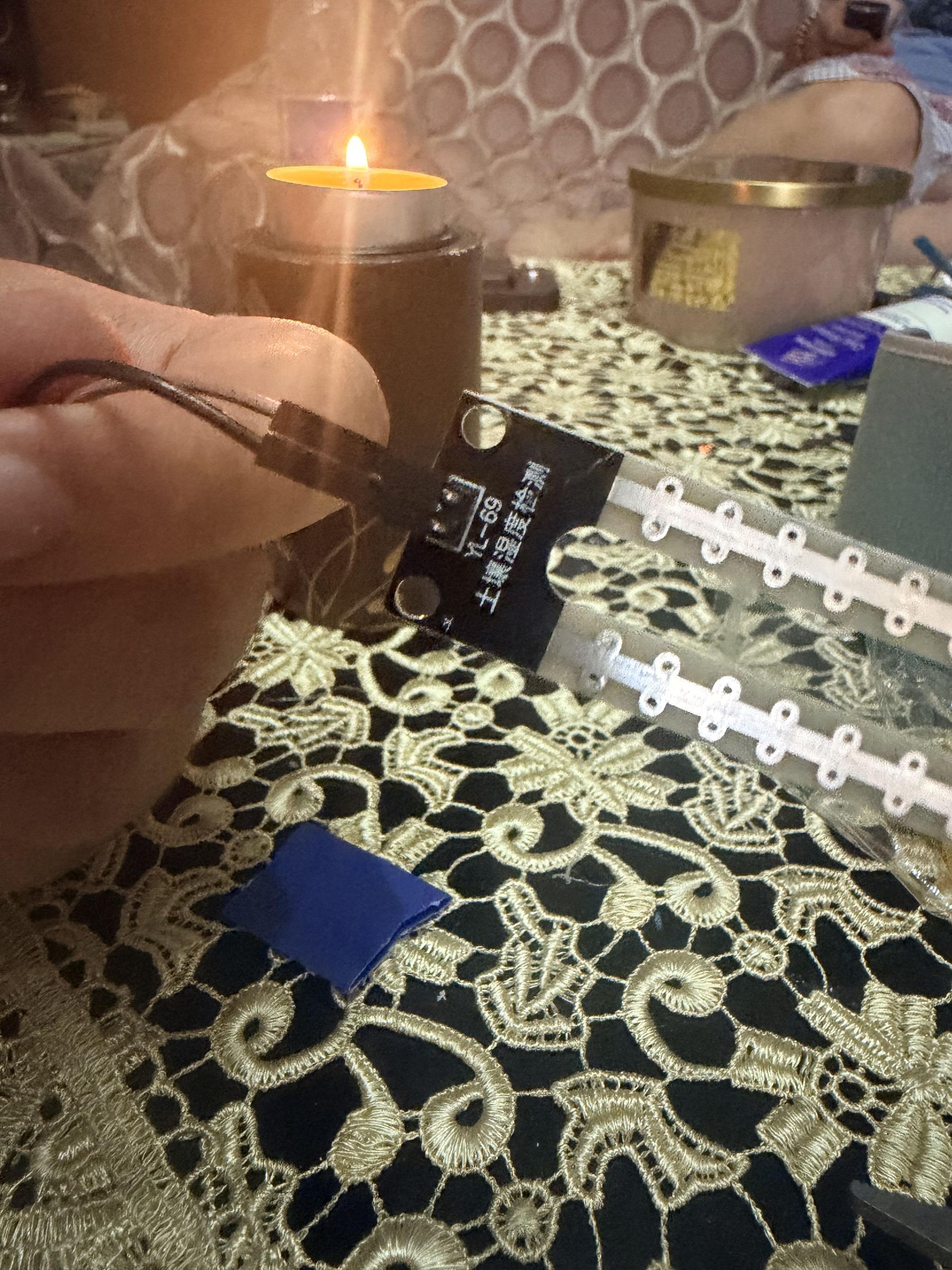
- Soil Moisture Sensors, used for monitoring soil humidity levels and supporting automated irrigation decisions.
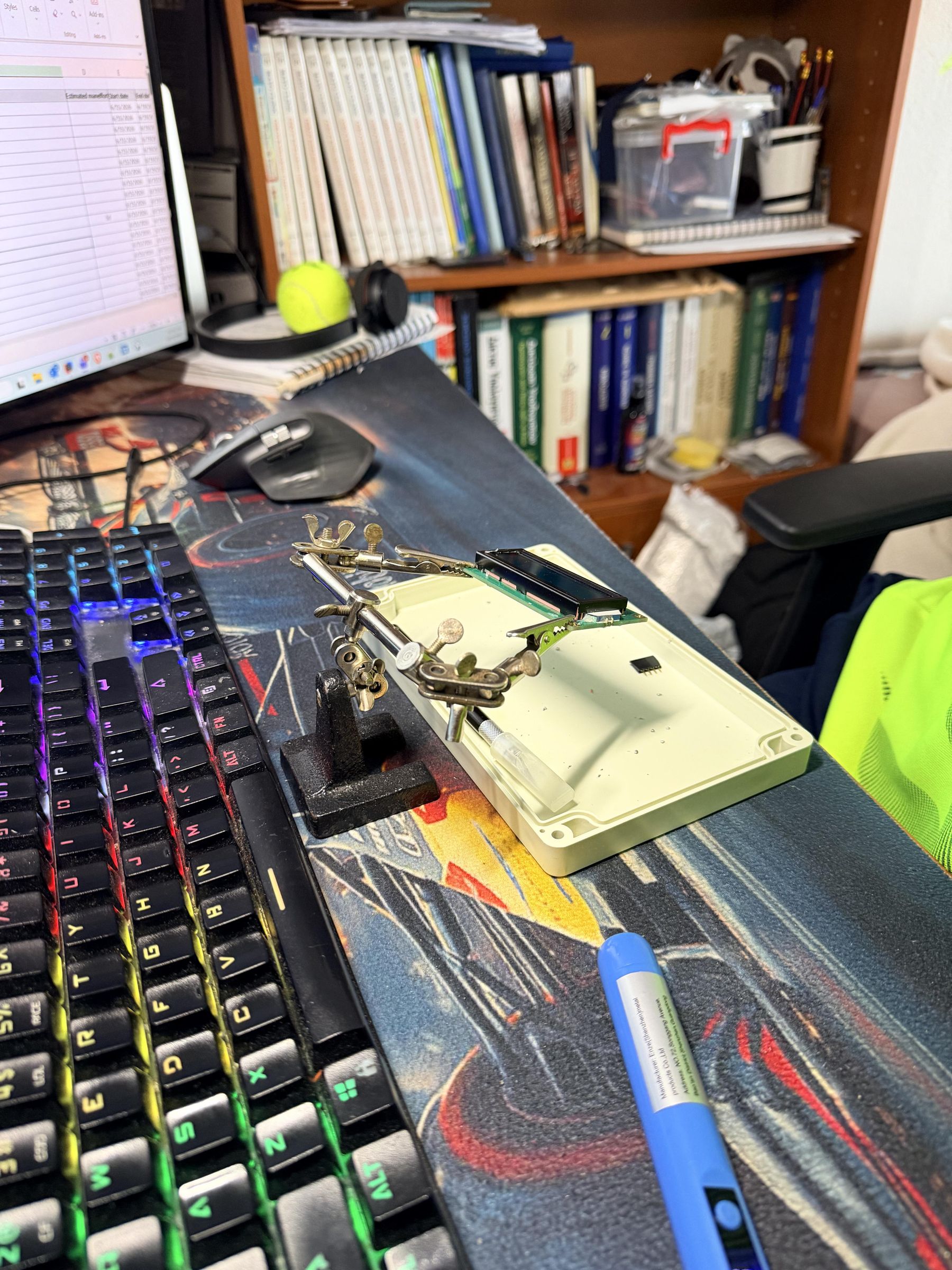
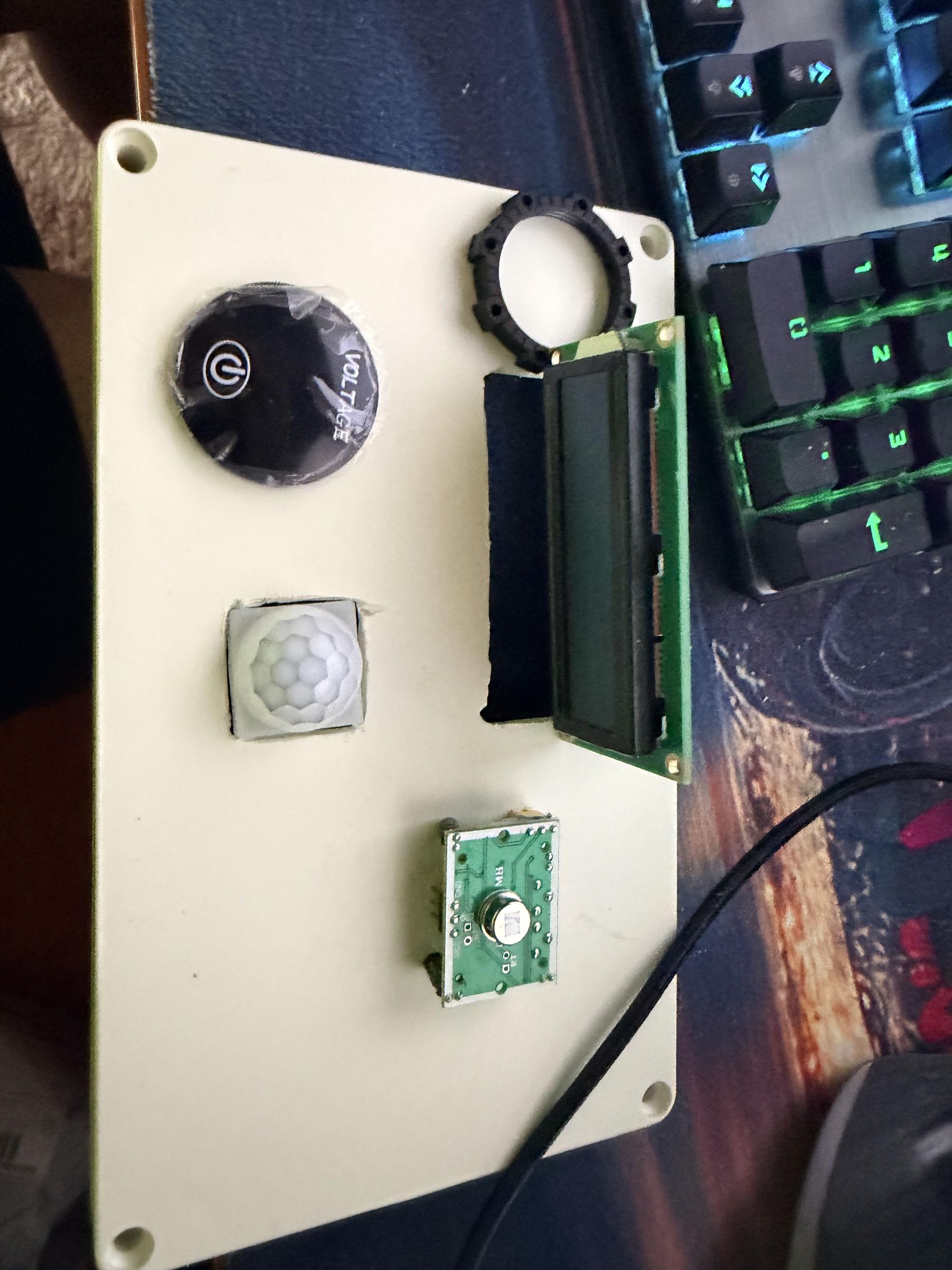
- PIR (Passive Infrared) Motion Sensor, used for motion detection. The sensor activates the LCD display only when movement is detected, reducing unnecessary power consumption and improving energy efficiency.
Power Supply and Energy Management Components
- 12V Rechargeable Battery, used as the primary energy storage source for the autonomous greenhouse system.
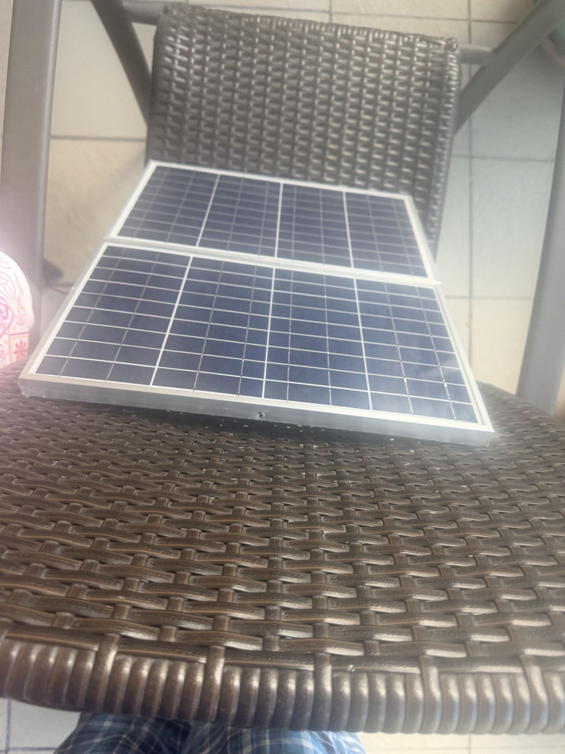
- Solar Panel, used for charging the battery and providing renewable energy support.
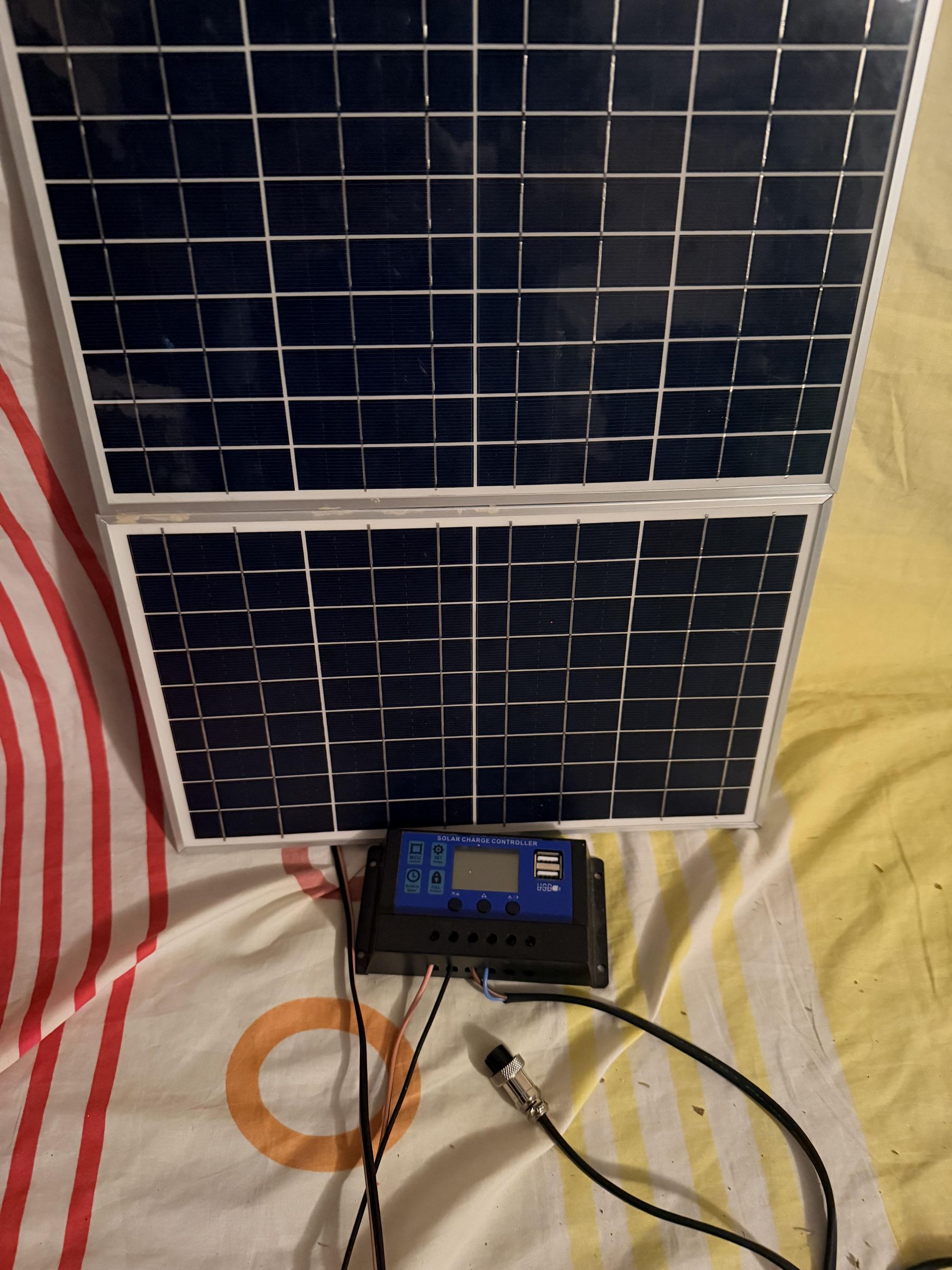
- Solar Charge Controller, responsible for regulating battery charging and protecting the battery from overcharging and excessive discharge.
- Battery Voltage Meter / Percentage Indicator, used for monitoring the battery voltage and available charge level.
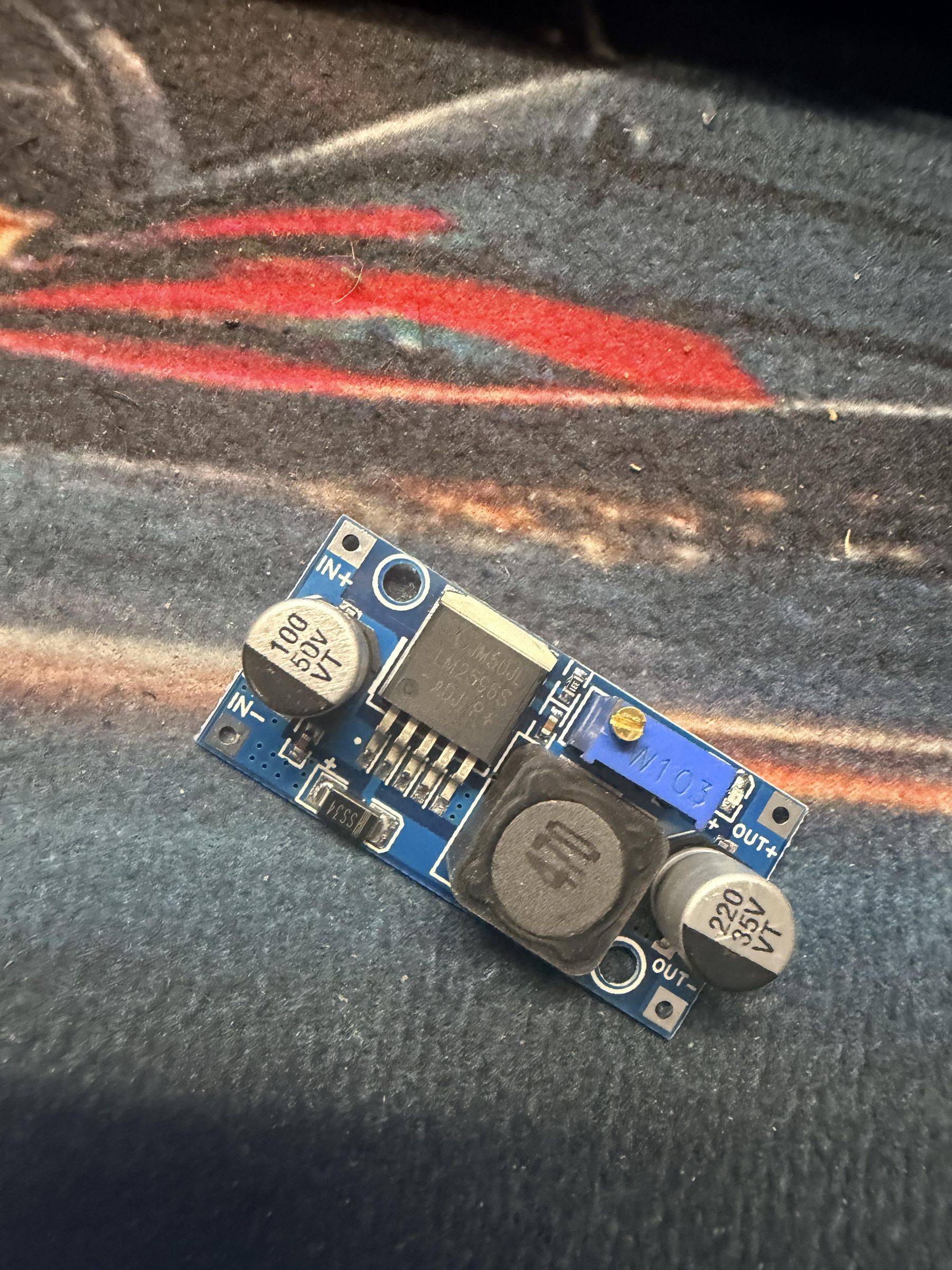
- Two DC-DC Step-Down (Buck) Converter Modules (12V to 5V), used to provide stable 5V power supply for low-voltage electronic components such as microcontrollers and peripheral devices.
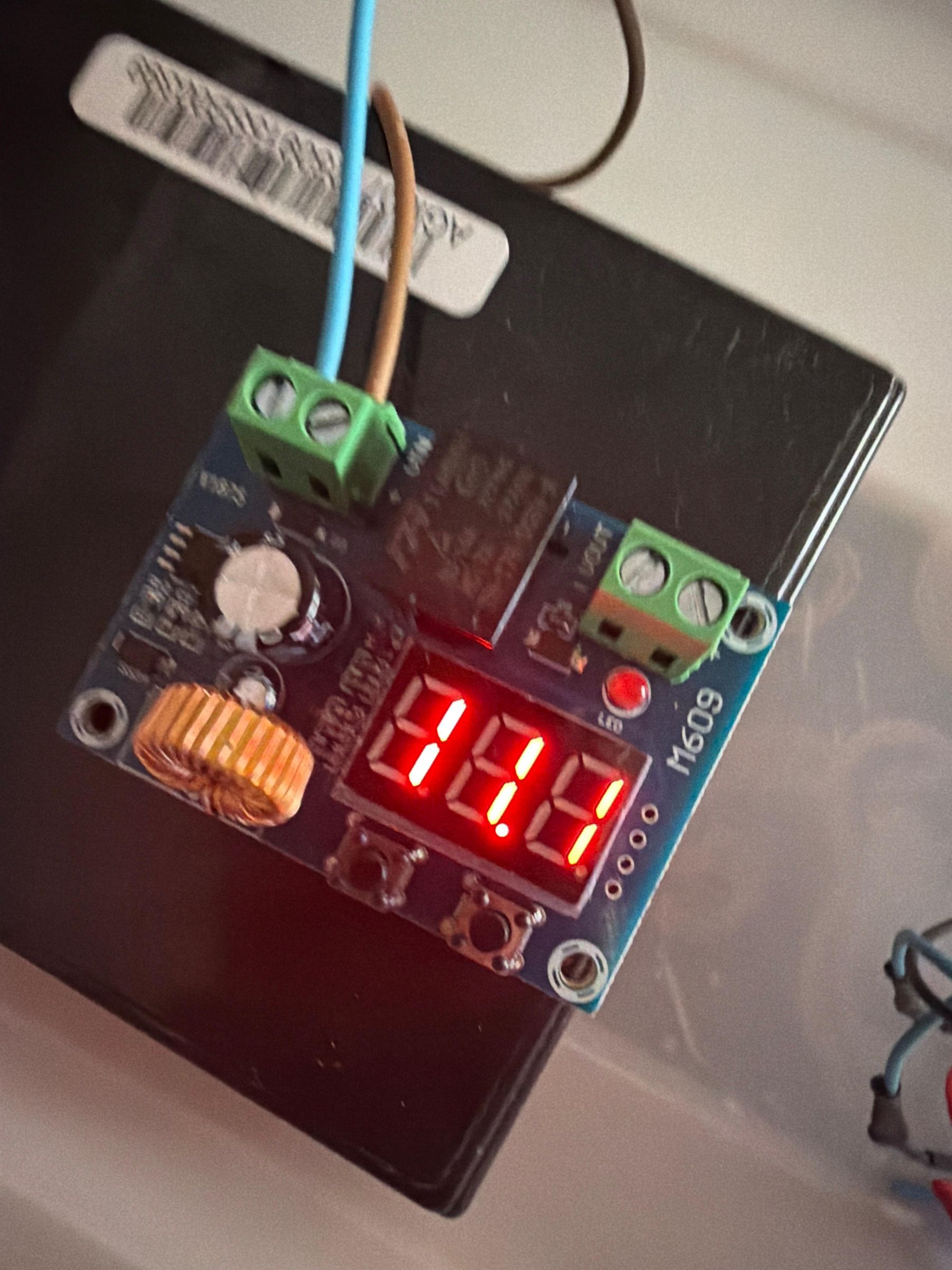
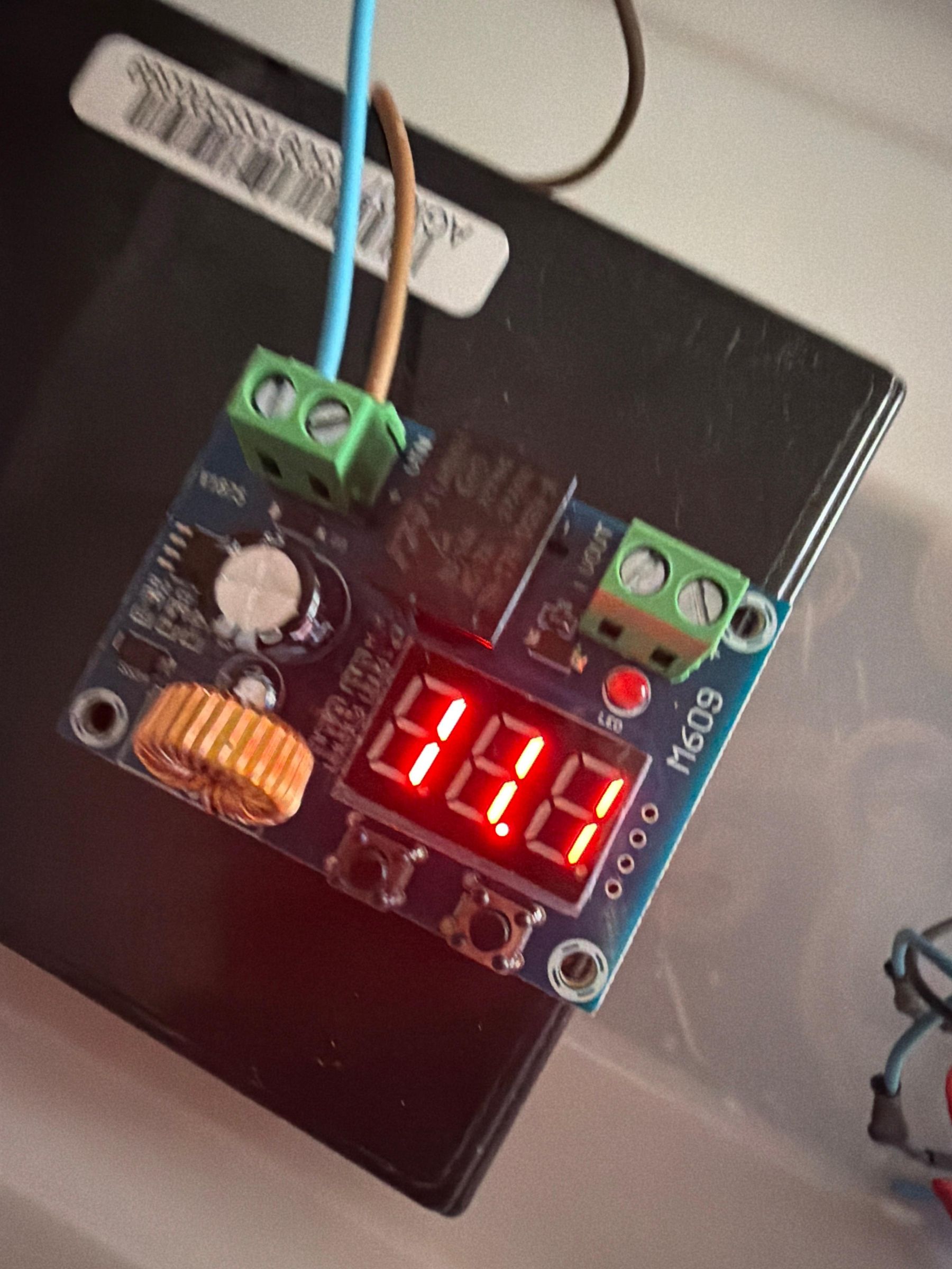
- Automatic Low Voltage Disconnect Protection Module, used to automatically disconnect the power supply when the battery voltage drops below 11.5V. This protection mechanism prevents deep battery discharge and improves battery lifetime.
- Electrical Fuses and Fuse Holders, used for circuit protection against overcurrent conditions.
- Automotive Fuse Boxes and Fuse Holders, providing organized and secure protection for the electrical distribution system.
Automation and Actuation Components
- Relay Modules, used for controlling external electrical devices.
- Water Pump, used for automated irrigation.
- Ventilation Fan, used for temperature regulation.
- Heating Element, used for maintaining suitable environmental conditions.
Enclosure and Protection Components
- Waterproof Electrical Boxes, used for protecting electronic components from moisture, humidity, and environmental conditions inside the greenhouse.
- Breadboards, jumper wires, resistors, voltage divider circuits, and electrical connectors used for prototyping and system integration.
- LCD Display with I2C Interface, used for local visualization of sensor measurements, battery status, and system information.
Software Components
- Raspberry Pi OS
- Docker and Docker Compose
- Spring Boot Framework
- Angular Framework
- PostgreSQL Database
- Eclipse Mosquitto MQTT Broker
- Java 21
- Node.js and npm
- Arduino IDE
- IntelliJ IDEA
- Visual Studio Code
Communication Technologies
- MQTT Protocol for lightweight and reliable communication between IoT devices and backend services.
- REST APIs for communication between the Angular frontend application and Spring Boot backend.
- Wi-Fi Network (IEEE 802.11) for wireless connectivity.
Development Libraries
- PubSubClient Library
- DHT Sensor Library
- ArduinoJson Library
- PrimeNG UI Components
- Chart.js for real-time data visualization
The complete system architecture integrates embedded electronics, renewable energy management, wireless communication, backend processing, database storage, and web-based monitoring. The combination of solar-powered operation, battery protection mechanisms, waterproof enclosures, and intelligent control algorithms enables reliable operation in real greenhouse environments.
Data Flow Explanation


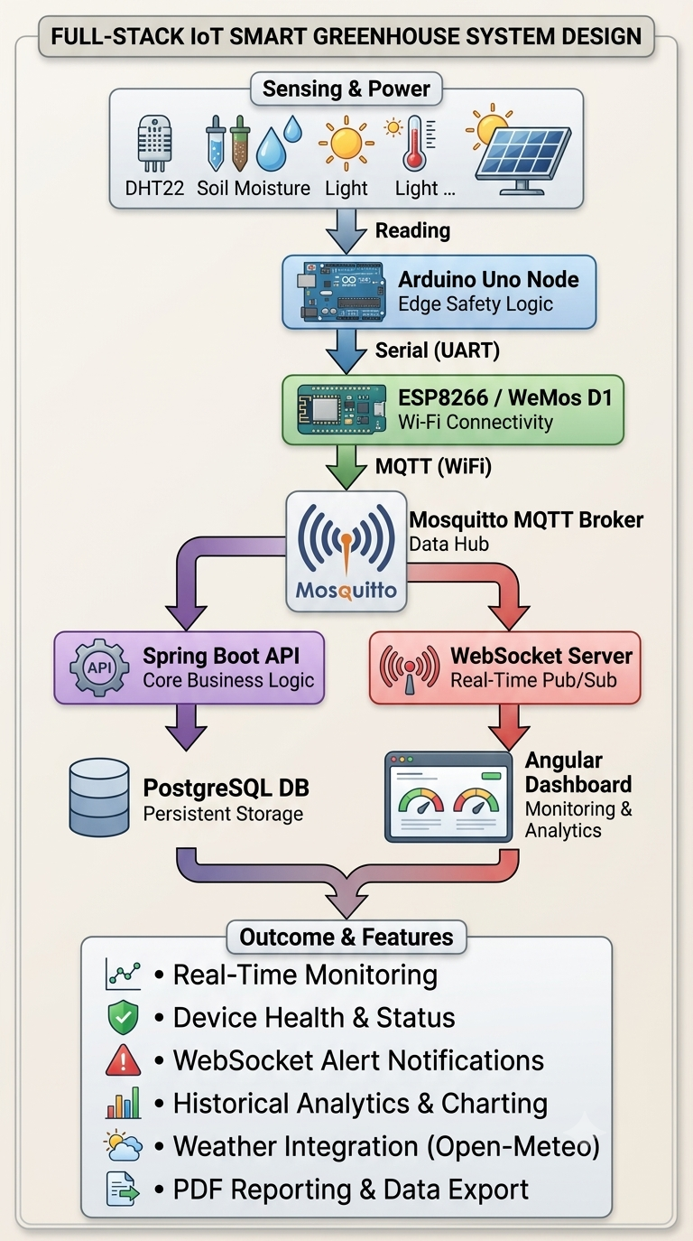
The system employs an end-to-end data pipeline spanning from physical sensors up to a cloud-ready web application:
Data Flow Explanation:
- Sensing Layer: Analog and digital sensors continuously collect greenhouse environmental metrics.
- Edge Processing Layer: The Arduino Uno reads these raw values, runs local safety logic, and forwards the structured packet to the WeMos D1 Mini over a hardware/software serial port (UART).
- Transmission Layer: The WeMos module connects to the local greenhouse Wi-Fi network and publishes the data payload to designated MQTT topics.
- Gateway & Server Layer: A Raspberry Pi acts as the central server. Its local Mosquitto broker receives the MQTT messages.
- Application Layer: The Spring Boot backend consumes the MQTT messages, validates them, saves them to the PostgreSQL database, and exposes REST APIs.
- Presentation Layer: The Angular frontend requests data from the backend and renders real-time gauges, historical charts, and system controls for the user.
System Architecture
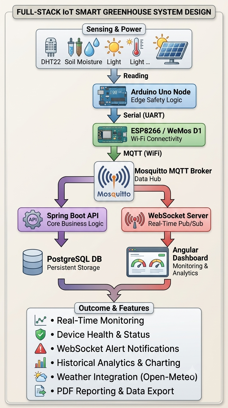
The system follows a layered IoT architecture:
Sensor Layer
Responsible for collecting environmental measurements using connected sensors.
Communication Layer
Uses MQTT protocol for reliable message exchange between IoT devices and backend services.
Backend Layer
Developed using Spring Boot, responsible for:
- Data processing
- Sensor management
- Measurement storage
- Alert generation
- REST API services
Data Layer
PostgreSQL database stores:
- Sensor information
- Measurements
- Historical data
- System events
Presentation Layer
Angular dashboard provides:
- Real-time monitoring
- Analytics
- Notifications
- Device management
Hardware Design and Implementation

The core logic is split across two microcontrollers to achieve absolute modularity and system stability:
Arduino Uno
- Role: Sensor Acquisition & Execution Hub.
- Key Duties: Reading analog and digital sensor outputs, executing local time-critical automation logic, and triggering the high-current relay switches.
WeMos D1 Mini / R2 (ESP8266)
- Role: IoT Wireless Gateway.
- Key Duties: Managing Wi-Fi connectivity, handling network reconnection routines, and publishing structured sensor data to the local MQTT broker.
Sensor Suite
The greenhouse node integrates a comprehensive array of sensors to capture a complete picture of the microclimate:
- 2x Soil Moisture Sensors: Positioned in different plant beds to monitor root hydration (measured in %).
- 2x Temp/Humidity Sensors (DHT22): Provide high-accuracy air temperature (°C) and relative humidity (%) readings.
- 1x Light Sensor (Photoresistor/LDR): Monitors ambient sunlight levels to determine if artificial lighting is needed.
- 1x PIR Motion Sensor: Domed presence detector to secure the site and automate local human-interface systems.
- 1x Battery Voltage Sensor: A voltage divider circuit to track power bank levels.
Actuators & Relays
Physical devices are controlled via an optically isolated 4-Channel Relay Module (5V/12V), mapping low-voltage microcontroller pins to high-power components safely:
- Relay 1 → 5V Water Pump: Submersible pump used for automated drip irrigation.
- Relay 2 → 12V PC Fan: Active extraction fan used for hot air ventilation.
- Relay 3 → LED Grow Light / UV Light: Simulated sunlight to extend photoperiods (future implementation).
- Relay 4 → Expansion Port: Reserved for future devices (such as a mist humidifier or heating pad).
Power System (Solar Charge & Power Box)
Designed as a standalone, portable power distribution box, this subsystem manages green energy generation and system protection:
- Solar Charging & Regulation: Powered by two Photovoltaic (PV) solar panels wired in parallel, routed through a 10A Solar Charge Controller to safely charge a 12V AGM Lead-Acid Battery.
- Safety Fusing: Built-in in-line fuse blocks provide essential short-circuit protection across various branches:
- 10A Fuse: Charge Controller to Battery line.
- 5A Fuse: High-current Actuator branch (pumps/fans).
- 3A Fuse: Core sensor distribution rail.
- 1A Fuse: Delicate microcontroller lines.
- Low-Voltage Disconnect (LVD): Features an XH-M609 module programmed to cut off the load if battery voltage drops below 10.5V or 11V (e.g., during long cloudy periods), preventing permanent cell degradation.
- Chassis & Interfaces: Housed in a waterproof, rugged plastic tub. The exterior panel features key connectivity interfaces:
- Dedicated DC power jacks (labeled "Arduino" and "Sensor").
- GX16 Aviation Plug connectors (labeled "12V Out" and "Pump") for heavy-duty, screw-locked physical connections.
- Master Rocker Switch for instant manual hardware shutdown.
Control Box 1 - Main IoT Node
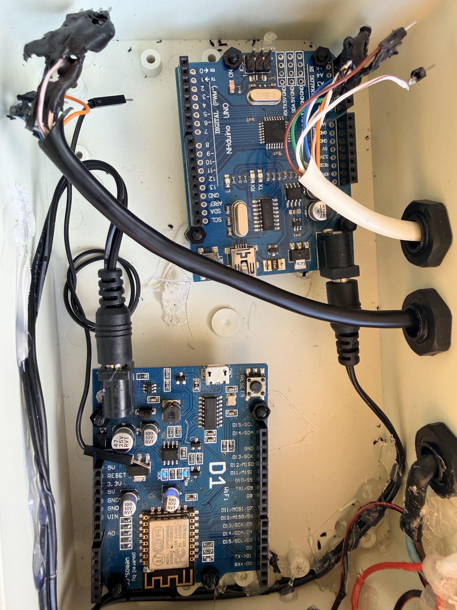
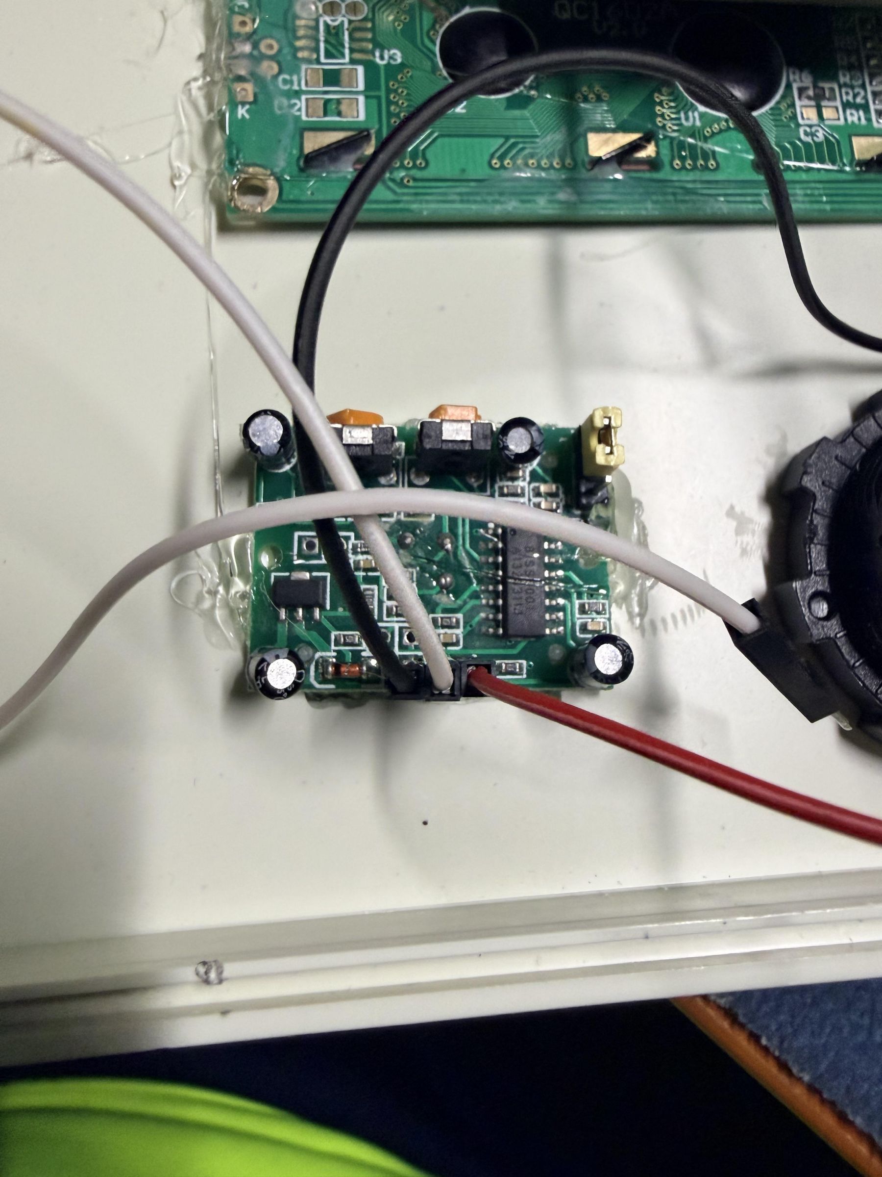
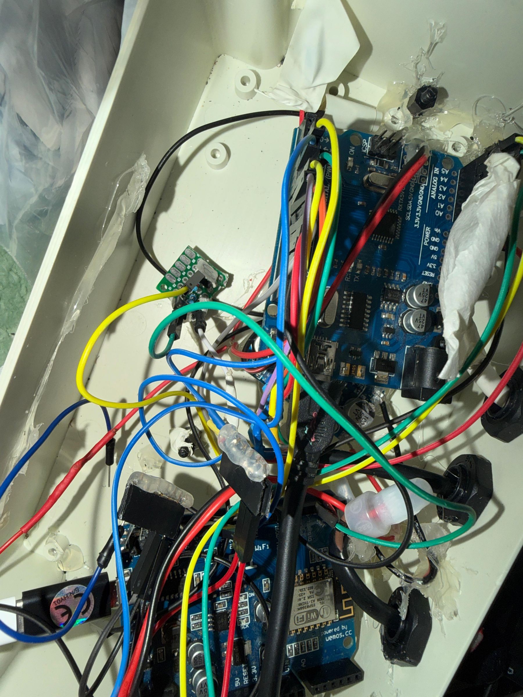
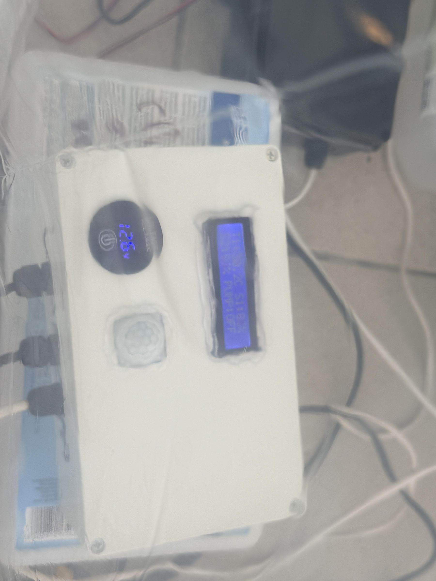
This unit is the weatherproof "brain" of the greenhouse, housed in a sealed ABS plastic junction box:
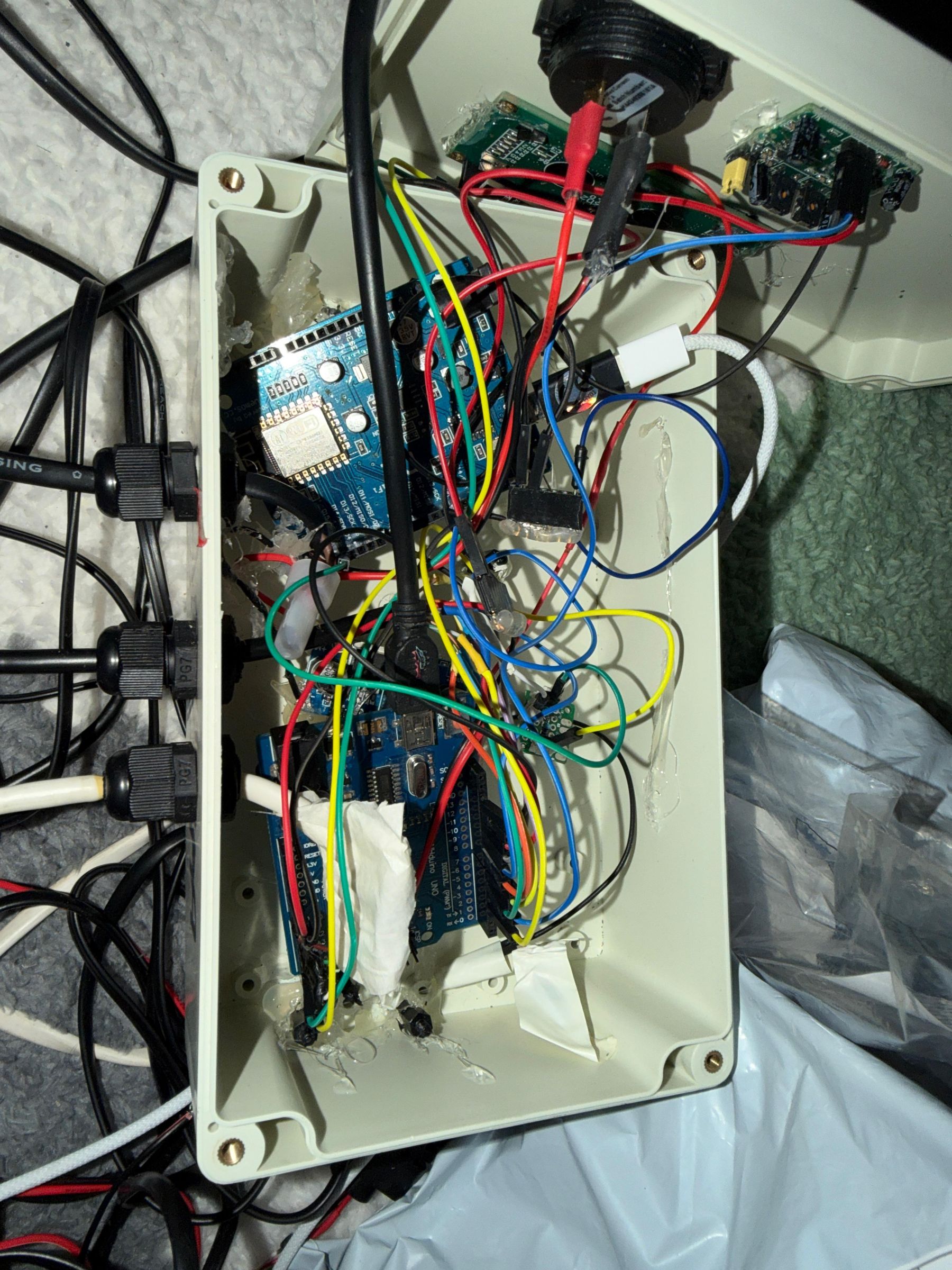
- Integrated Processing Stack: Hosts both the Arduino Uno and the WeMos D1.
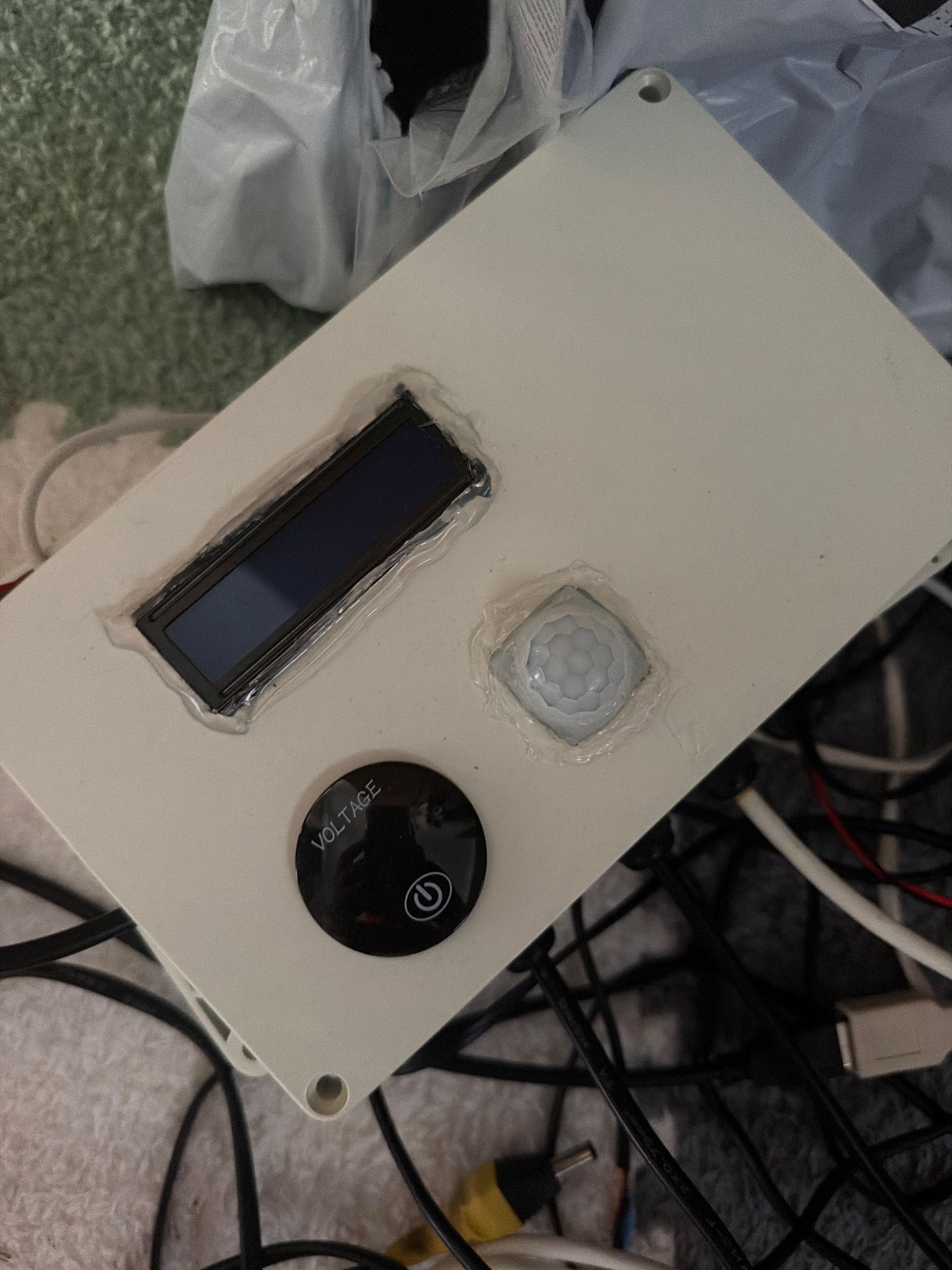
- Power-Efficient Local User Interface: Features a front-mounted 16x2 LCD screen with an I2C backpack. To maximize battery life, the LCD backlight remains OFF by default. It only activates when the PIR Motion Sensor detects a human operator nearby.
- Manual Diagnostics: A round, tactile "VOLTAGE" push button is mounted on the front panel, allowing an on-site operator to cycle through live sensor diagnostics or check battery status on the screen.
- Environmental Sealing: All data and power lines enter through heavy-duty PG7/PG9 cable glands, protecting the internal microcontroller boards from high humidity and condensation.
Control Box 2 - Field Control Unit
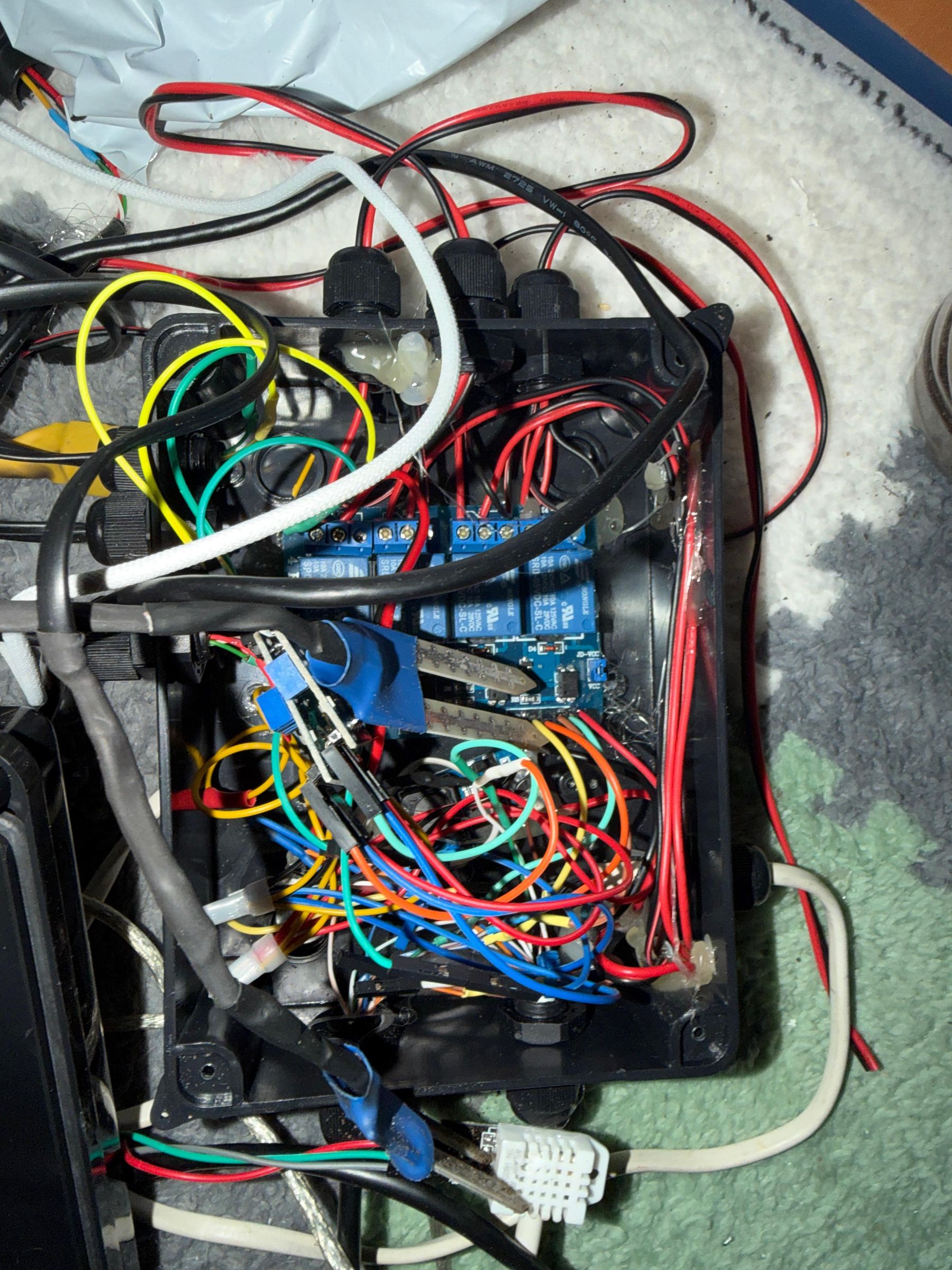
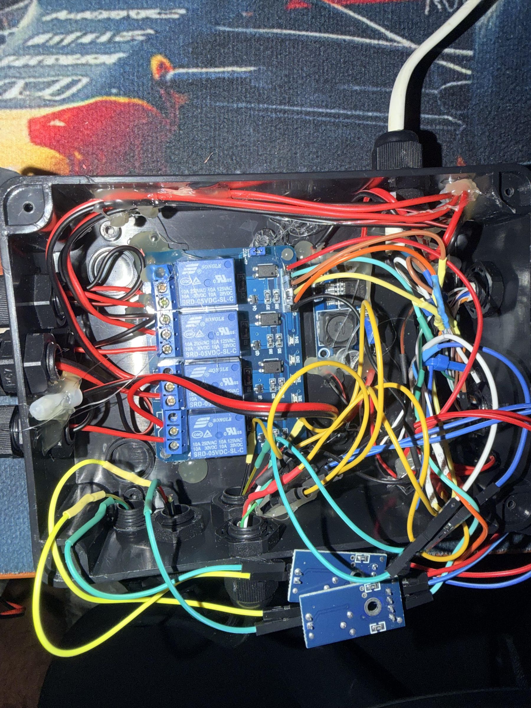
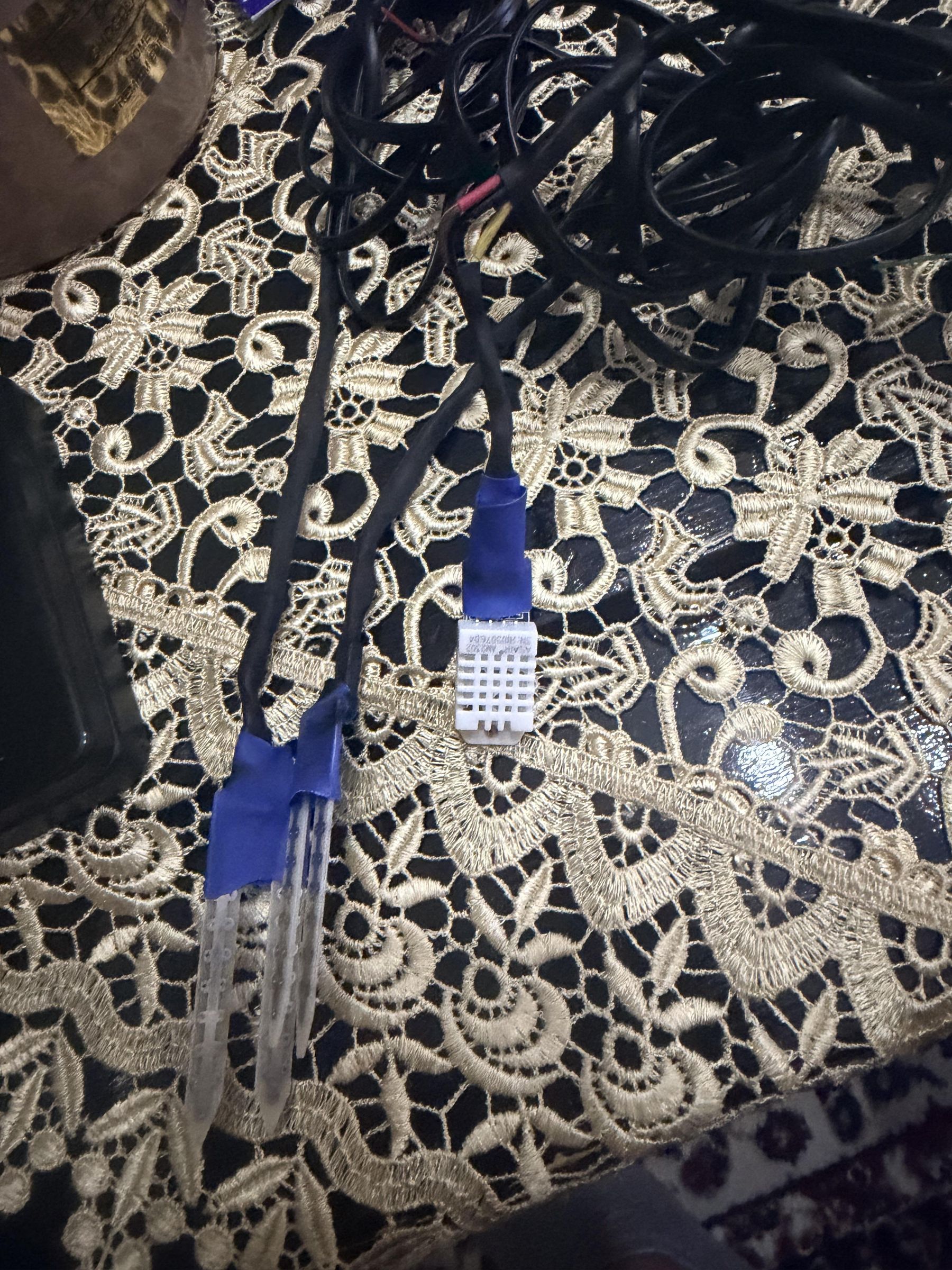
Located directly in the field adjacent to the crops, this rugged black ABS junction box serves as the connection interface for environmental components:
- Load Control: Houses the 4-channel relay board, keeping high-voltage switching isolated from the main processor box.
- Direct-Fit Sensors: Connects to the highly accurate DHT22 air sensor and capacitive, corrosion-resistant Soil Moisture probes embedded directly in the plant beds.
- Heavy Weatherproofing: All wiring harnesses are protected with heat-shrink tubing, terminal blocks, silicone sealing, and waterproof connectors to withstand water splashes and soil moisture.
Water Reservoir & Drip Irrigation Pump Assembly
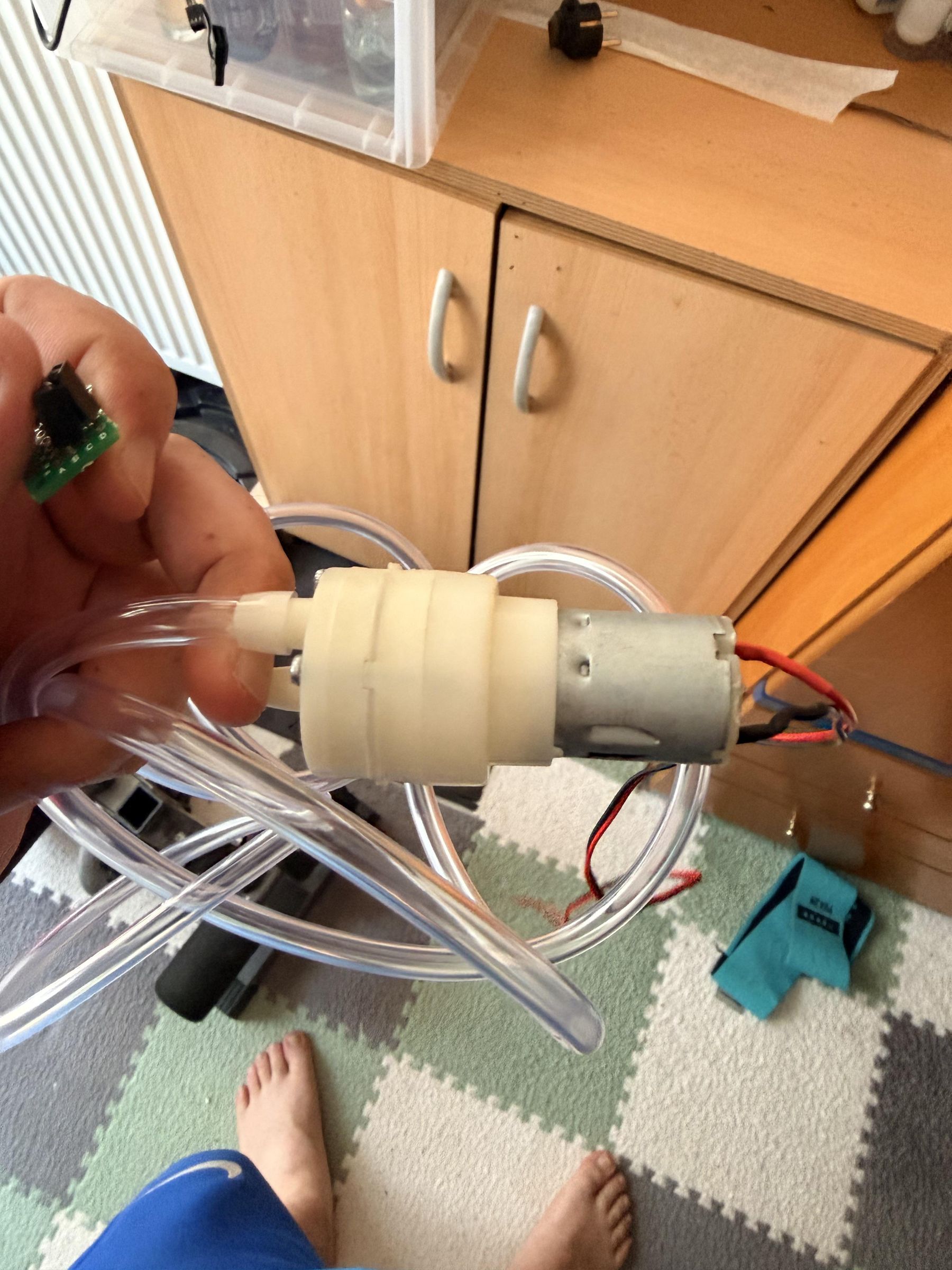
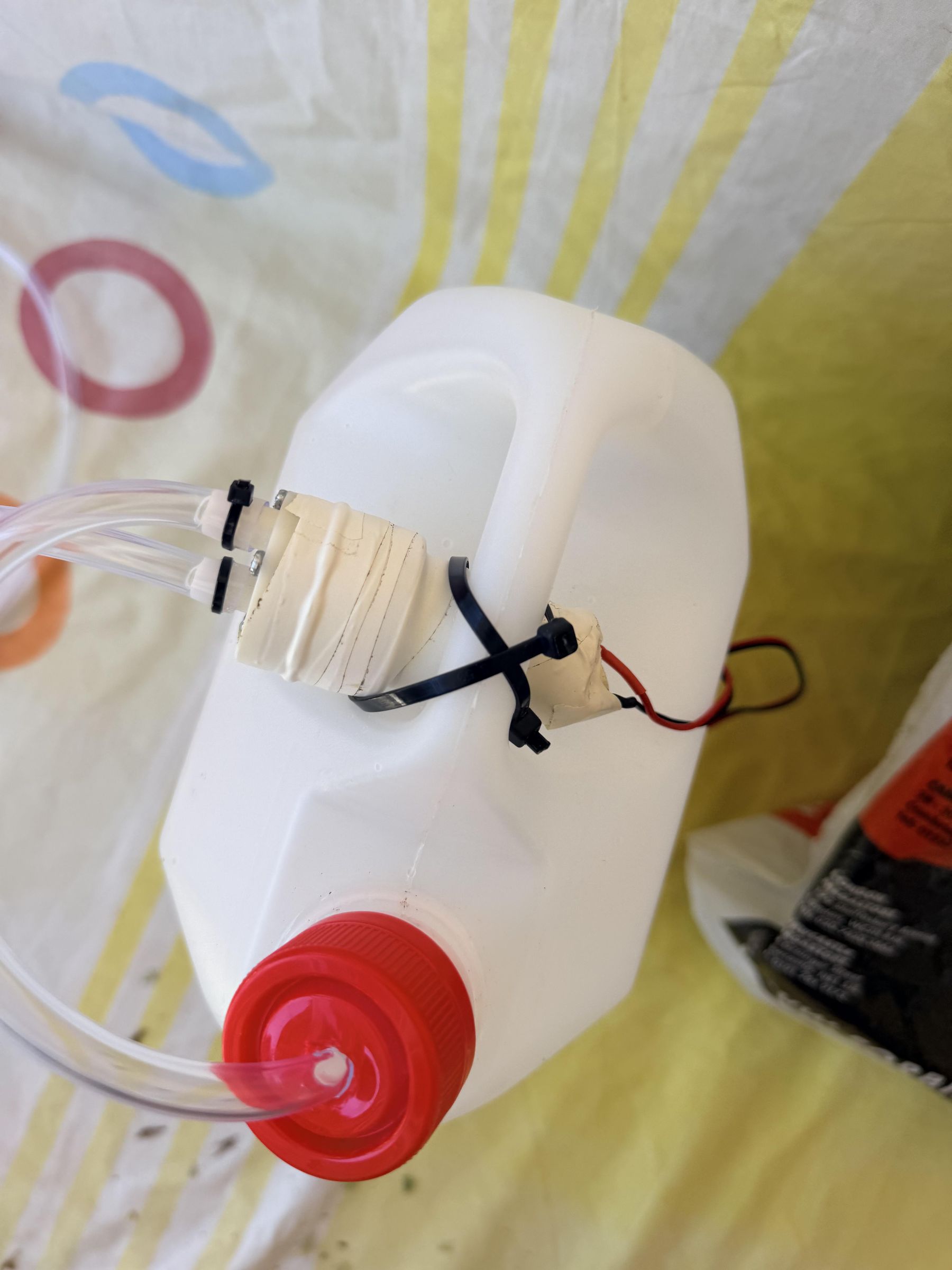
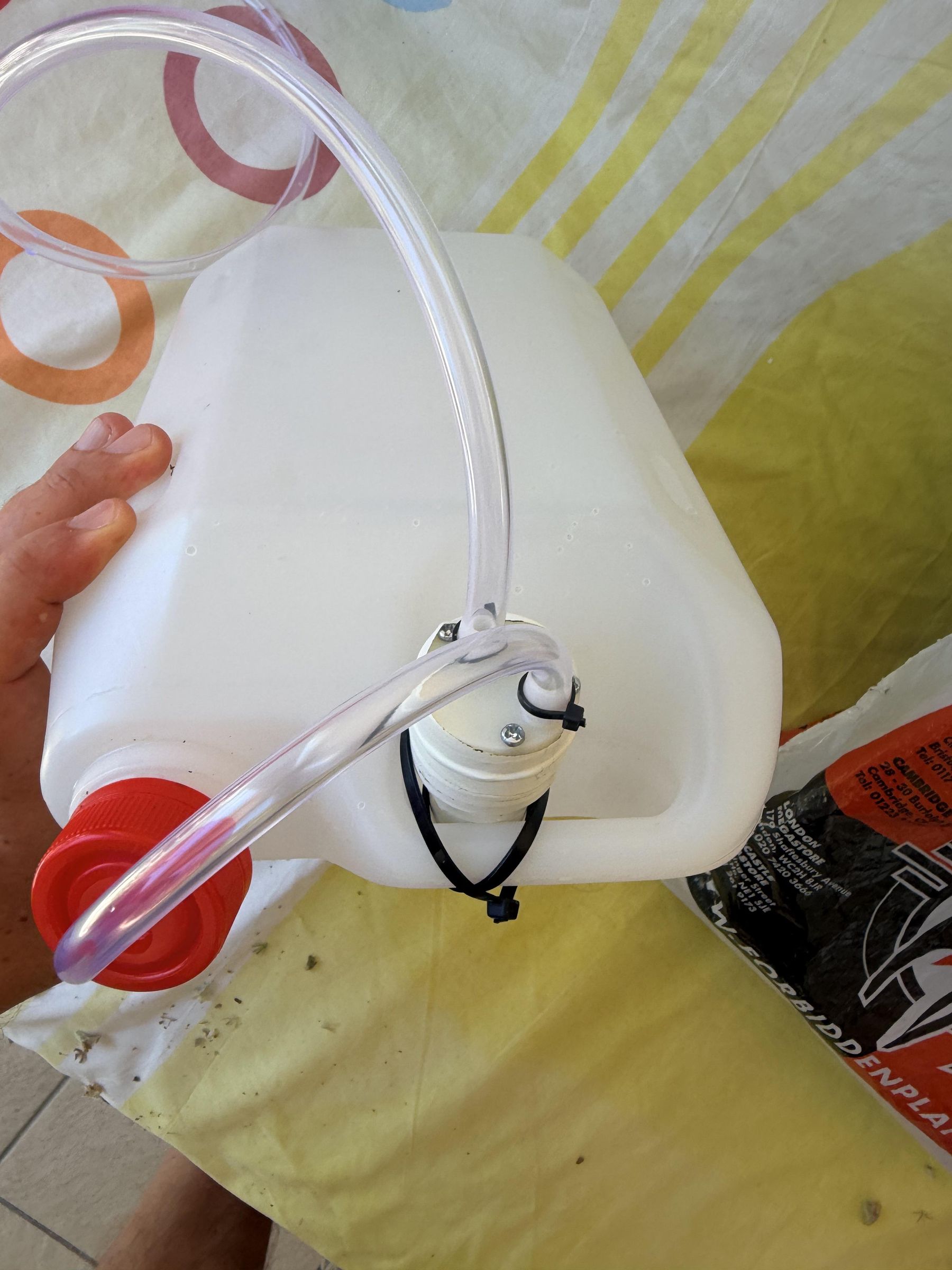
To achieve a fully automated, standalone watering loop, a custom gravity-independent water pump system was constructed:
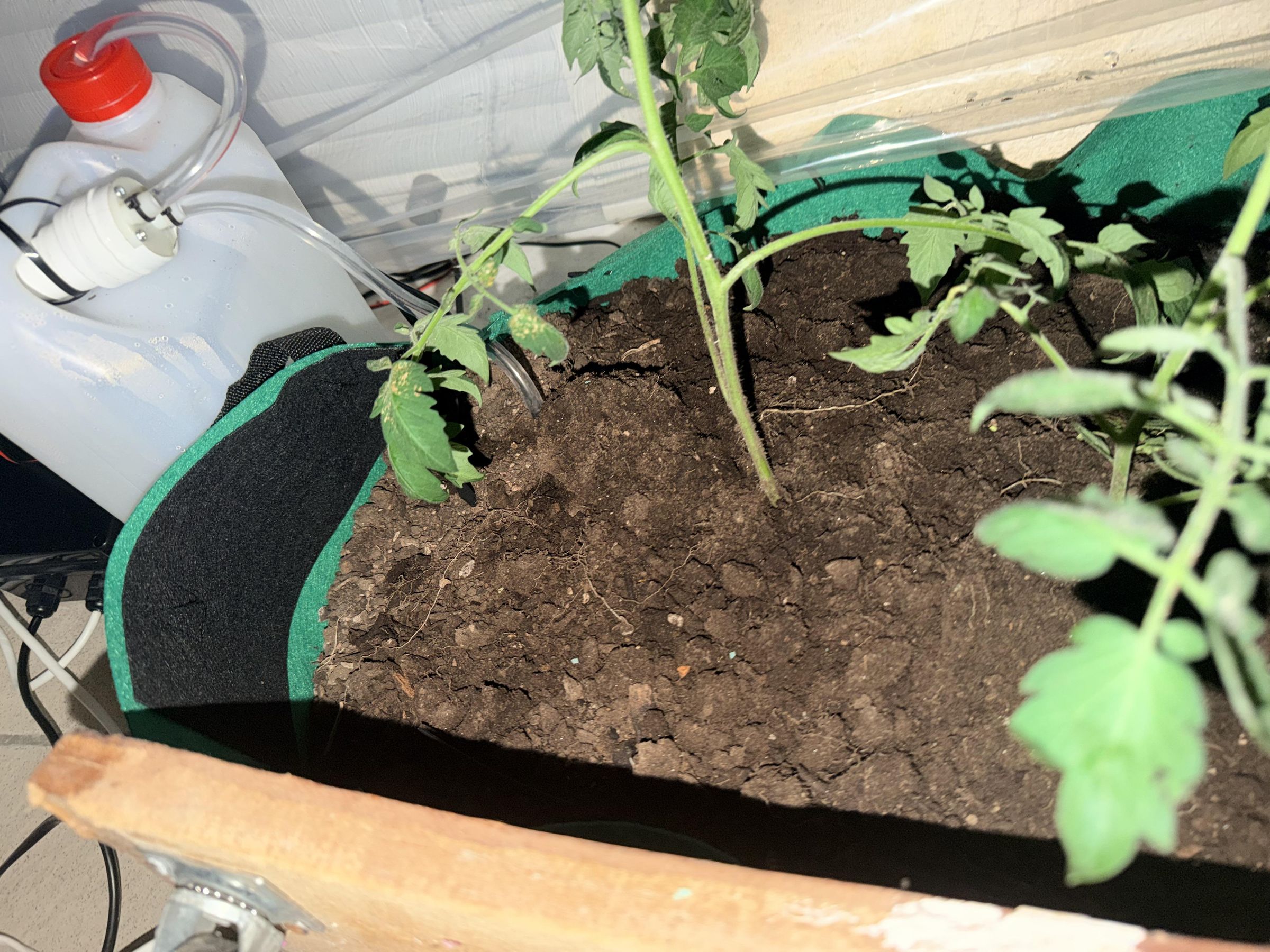
- The Reservoir (Canister/Jerrycan): A recycled heavy-duty plastic canister (jerrycan / "betoni") serves as the primary water storage tank. This container keeps the water supply sealed to prevent debris, dust, or algae growth from clogging the system.
- Submersible Pump Integration: A compact 5V DC water pump is placed directly at the bottom of the water canister. It is wired back to Control Box 2 (Field Box) via waterproof cables sealed with silicone.
- Plumbing & Distribution: Vinyl tubing connected to the pump outlet runs out of the canister's cap. The tube branches out into a drip irrigation manifold, guiding targeted water streams directly to the root zones of the plants inside the garden bed.
Power System Design and Battery Protectio
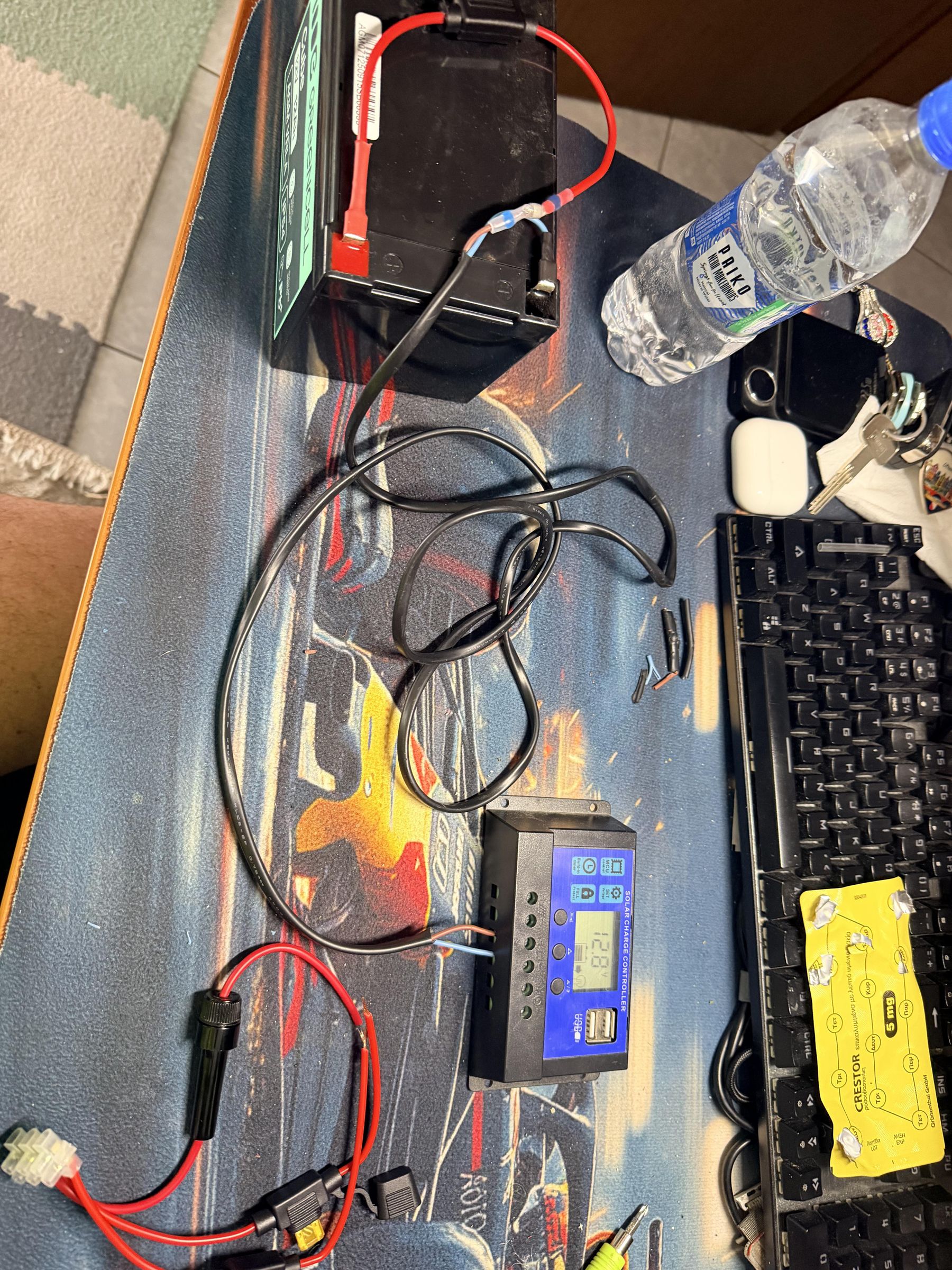
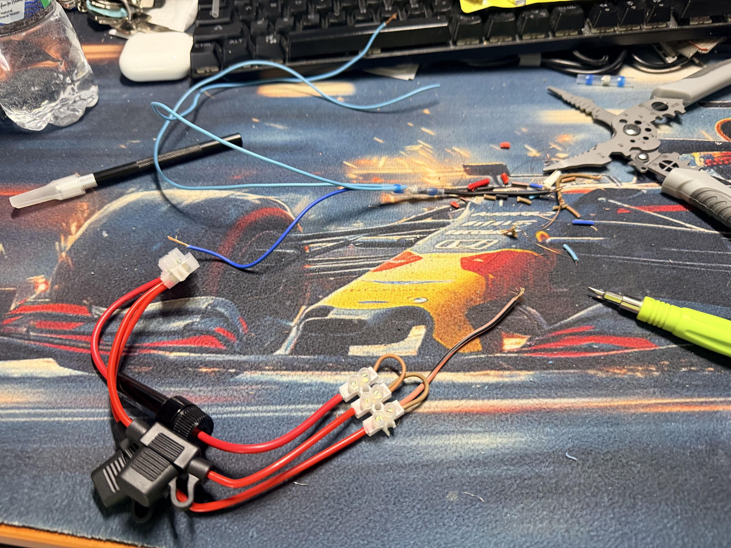
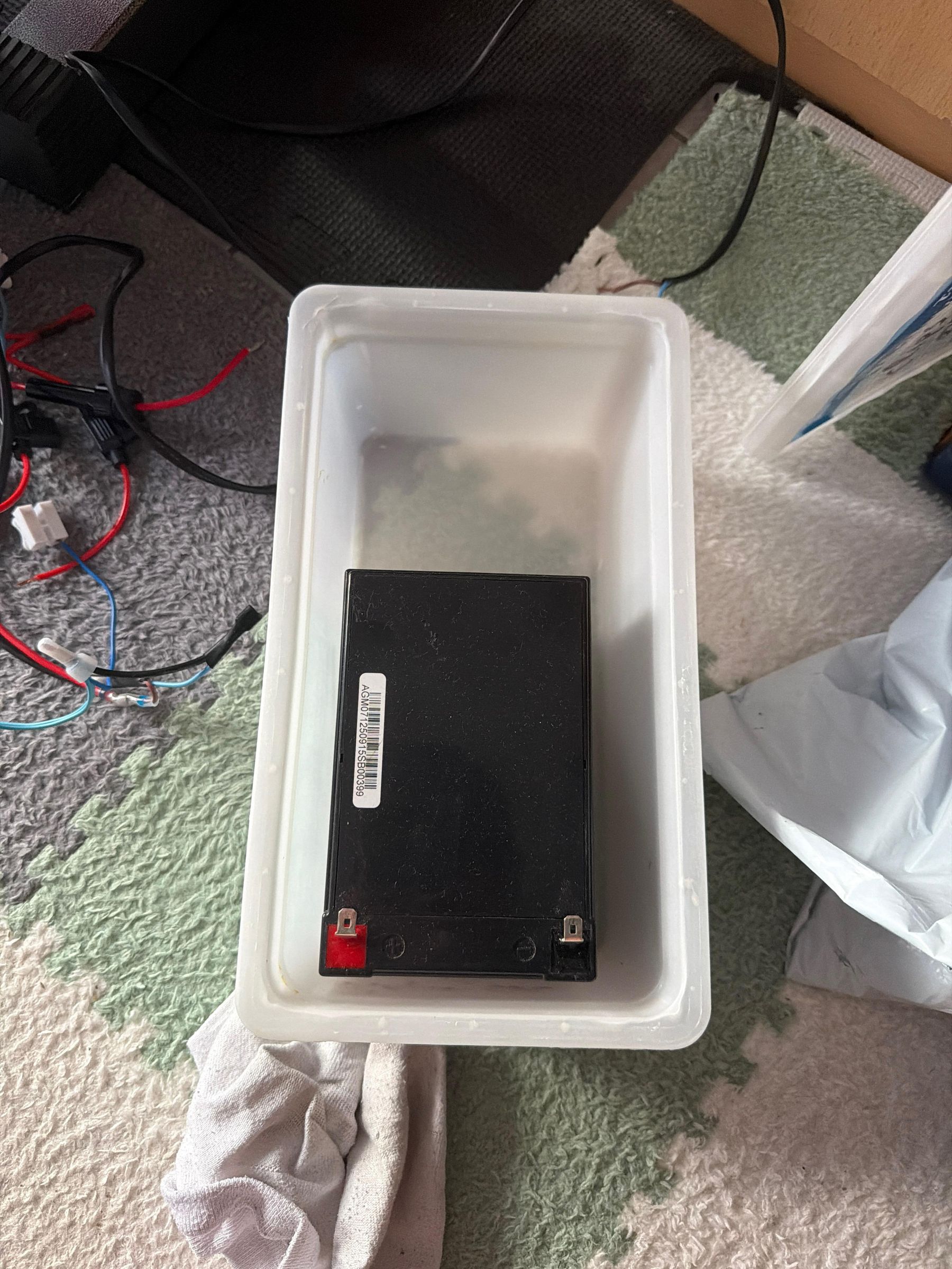
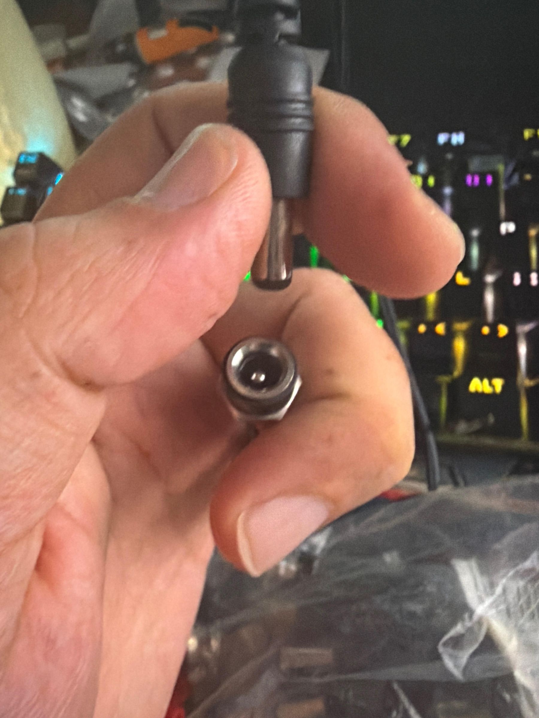
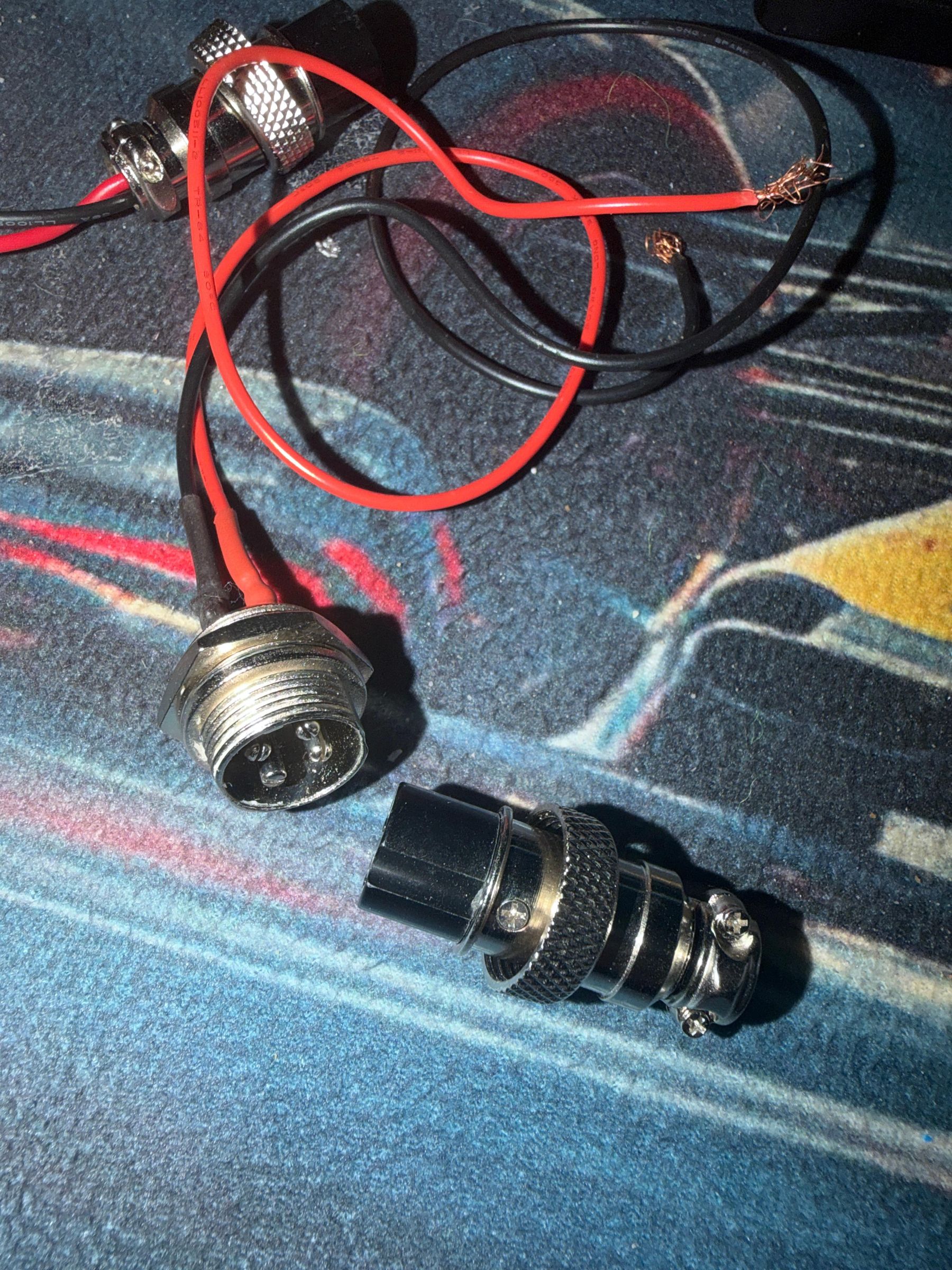
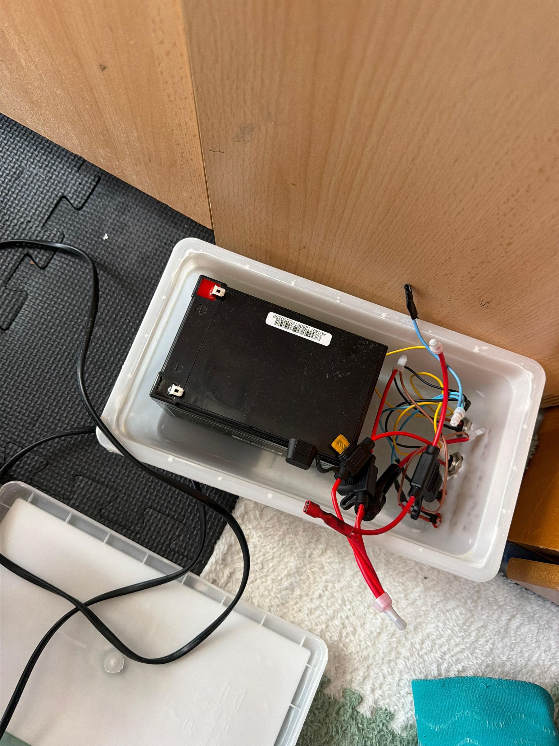
The Smart Greenhouse system was designed to operate as an autonomous off-grid platform using renewable solar energy. The power subsystem was developed to provide stable voltage distribution, protect electronic components, and ensure safe long-term operation under outdoor environmental conditions.
Solar Energy Generation and Battery Storage
The energy system is based on a 12V rechargeable battery, which acts as the main power storage unit for the greenhouse. The battery is charged through photovoltaic solar panels connected to a solar charge controller. The charge controller regulates the charging process and protects the battery from overcharging and excessive discharge.
The stored energy is distributed to the different system components through a dedicated power management board. This architecture allows the greenhouse to operate independently from the electrical grid, making it suitable for remote agricultural environments.
Voltage Regulation
Since the system contains components operating at different voltage levels, DC-DC step-down converters are used to provide stable low-voltage power supplies.
Two DC-DC buck converter modules are integrated into the power system:
- One 12V to 5V step-down converter supplies power to the Arduino Uno, relay modules, LCD display, and other 5V electronic components.
- A second 12V to 5V step-down converter provides an independent regulated supply for additional low-voltage electronics, improving system stability and reducing interference between different subsystems.
Battery Low Voltage Protection
To prevent permanent battery damage caused by deep discharge, an automatic Low Voltage Disconnect (LVD) protection module is installed between the battery and the system loads.
The protection module continuously monitors the battery voltage and automatically disconnects the output power when the voltage drops below a predefined safety threshold (approximately 11.5V).
This mechanism protects the battery from excessive discharge during periods of low solar production, such as extended cloudy weather conditions, while increasing battery lifetime and maintaining system reliability.
When the battery voltage returns to a safe operating level, the system can restore power automatically.
Electrical Safety and Fuse Protection
To improve electrical safety and protect individual subsystems, the power distribution system includes dedicated fuses for each output branch.
The implemented protection scheme includes:
- 10A fuse: Protects the main charging path between the solar charge controller and the battery.
- 5A fuse: Protects high-current loads such as the water pump and ventilation fan.
- 3A fuse: Protects the main sensor and peripheral power distribution branch.
- 1A fuse: Protects sensitive electronic components, including microcontrollers and communication modules.
The use of separate fuse branches prevents a failure in one subsystem from affecting the complete greenhouse installation and simplifies maintenance and troubleshooting.
Waterproof and Environmental Protection
Since the greenhouse operates in an environment with high humidity, water exposure, and temperature variations, all critical electronic components are installed inside waterproof electrical enclosures.
The power distribution box and control boxes are protected using sealed plastic waterproof cases. Cable entries are performed through PG7 and PG9 waterproof cable glands, preventing moisture penetration while maintaining secure cable routing.
Additional protection measures include:
- Waterproof connectors for external sensor and actuator connections.
- Heat-shrink tubing on exposed electrical joints.
- Silicone sealing around cable entry points.
- Organized internal wiring using terminal blocks and fuse holders.
This construction approach improves system durability and allows reliable operation in real greenhouse conditions where electronics are exposed to humidity, condensation, and accidental water contact.
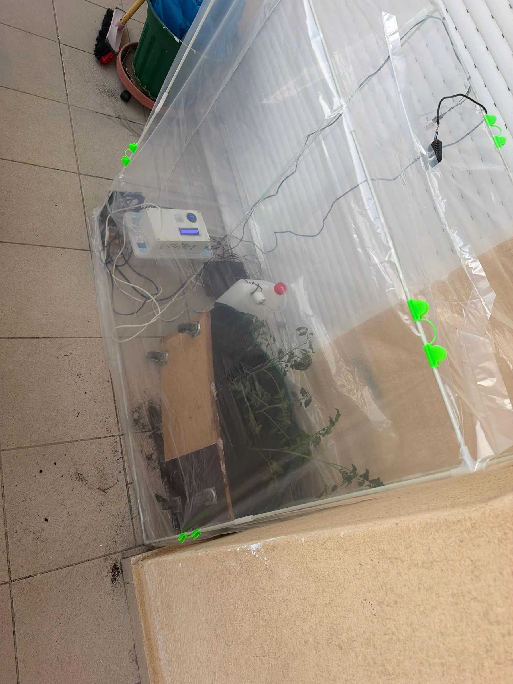
Greenhouse Frame, Covering & Raised Garden Bed
The physical structure of the greenhouse was designed to balance insulation, moisture retention, and cost-effective assembly:
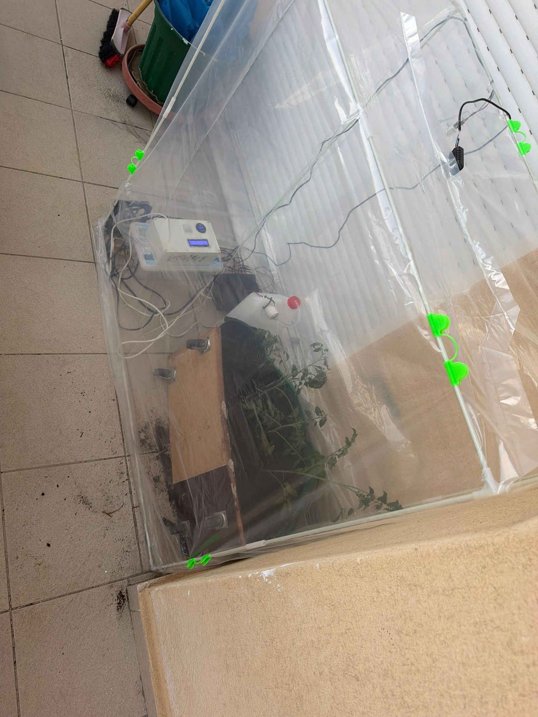
- Structure & Skeleton: The greenhouse dome/frame is constructed using flexible but sturdy plastic pipes (PVC/PEX). These pipes are bent into secure arches, forming a lightweight, wind-resistant Gothic-arch structural rib cage.
- Weatherproof Covering (Nylon Sheeting): A durable, heavy-duty agricultural polyethylene nylon sheet is wrapped and securely tensioned over the plastic pipe frame. This nylon acts as a thermal barrier, trapping solar heat (greenhouse effect), maintaining high relative humidity, and protecting the sensitive electronic nodes from direct rain.
- The Raised Garden Bed (Parteri): Underneath the canopy sits a dedicated soil bed containing the crops. This area is equipped with the two capacitive soil moisture probes, ensuring the microclimate directly surrounding the plants is continuously measured.
Communication Protocols & Logic

The system coordinates data across various physical layers:
Serial (UART) Link
- Pins: Arduino Uno Transmit Pin (TX 1) connected to the WeMos Receive Pin (RX).
- Data Type: Raw serial packages sent at regular intervals.
MQTT Protocol
- Connection: WeMos D1 connects to local Wi-Fi and publishes structured data to the Raspberry Pi Mosquitto Broker.
- Topics:
- greenhouse/sensor/register
- greenhouse/sensor/data
Raspberry Pi Server Architecture


The Raspberry Pi acts as the central local hub. It hosts the complete software stack containerized inside Docker for clean dependency isolation, with traffic routed through an Nginx Reverse Proxy:
[ Nginx Reverse Proxy ]
↓
┌───────────────────────┼───────────────────────┐
↓ ↓ ↓
[ Angular UI ] [ Spring Boot API ] [ Mosquitto Broker ]
↓ ↑
[ PostgreSQL DB ] ───────[ MQTT Subscriber ]
Software Backend (Spring Boot)


An enterprise-grade Java backend handles system coordination:
- MQTT Client Integration: Subscribes to the Mosquitto broker topics, reading incoming payloads asynchronously.
- Validation & Storage: Sanitizes incoming values and persists them to the database.
- Automation Engine: Constantly compares incoming readings against user-defined automation rules.
- REST API Endpoints: Exposes secure endpoints for the Angular frontend:
- GET /api/sensors - Lists all registered sensors.
- GET /api/readings - Fetches historical and live telemetry data.
- GET /api/alerts - Retrieves active safety or system alerts.
- POST /api/automation-rules - Creates or updates automation thresholds.
Database Schema

To keep track of system history, the PostgreSQL relational database employs the following schemas:
The sensors Table (Master/Metadata Table)
This table acts as a registry for all physical hardware deployment nodes within your greenhouse. Each row represents a specific physical sensor instance.
- id (Primary Key): A unique numerical identifier (integer) for each registered sensor.
- name (String/Text): The user-friendly label given to the sensor (e.g., "Soil Moisture Bed 1" or "Air Temp North").
- sensor_type (String/Text): The category of environmental metric it targets (e.g., Temperature, Humidity, Moisture, LDR).
- location (String/Text): Where the sensor is physically installed (e.g., "Control Box 2", "Root Zone").
- model (String/Text): The exact hardware manufacturer model designation (e.g., "DHT22", "YL-69").
- device_uid (String/Text): A unique hardware identifier or MAC address, helpful for device authentication or low-level identification.
The measurements Table (Time-Series Data Table)
This table is built to store the continuous stream of incoming telemetry data payloads generated over time.
- id (Primary Key): A unique numerical identifier for every single recorded entry.
- measurement_type (String/Text): The metric type recorded (e.g., "Celsius", "Percentage").
- unit (String/Text): The standard scientific unit symbol associated with the data point (e.g., "°C", "% ", "Lux").
- value (Numeric/Decimal): The actual numerical data reading captured at that exact moment.
- timestamp (DateTime): The exact date and time the reading was registered, which is vital for rendering your historical charts.
- sensor_id (Foreign Key): A reference back to the originating sensor hardware from the sensors table.
Table Relationships (The Link)
The blue dotted line represents a relational mapping constraint, specifically a One-to-Many Relationship:
- One Sensor -->Many Measurements: A single sensor row in the sensors table can have thousands or millions of corresponding historical telemetry records over time in the measurements table.
- The Foreign Key constraint: The field sensor_id inside the measurements table links directly to the id field inside the sensors table. This ensures referential integrity—you cannot insert a measurement entry for a sensor that has not been officially registered in your metadata configuration table first.
IoT-Based Smart Greenhouse Monitoring and Management System (Angular)


Web-Based Monitoring and Management Platform
The web interface allows users to monitor and interact with the Smart Greenhouse system from any device through a modern, responsive, and real-time dashboard.
Live Telemetry Monitoring
The dashboard provides real-time visualization of environmental sensor data, including:
- Soil moisture monitoring.
- Air temperature and humidity measurements.
- Air quality monitoring (planned future enhancement).
- Live sensor values updated through WebSocket communication.
- Visual indicators representing normal, warning, and critical environmental conditions.
This enables users to instantly observe greenhouse conditions and react to environmental changes.
Historical Data Visualization
Users can analyze sensor behavior through interactive historical charts and analytics tools.
Implemented features include:
- Interactive time-series charts using visualization libraries such as Chart.js or D3.js.
- Display of historical measurements for each sensor.
- Visualization of recent measurements and environmental trends.
- Easier identification of anomalies and long-term environmental changes.
- Exportable historical reports for maintenance and decision support.
Historical analytics provide valuable information for greenhouse optimization and preventive maintenance.
Sensor Management Panel
The interface provides complete sensor management capabilities:
- View all registered sensors.
- Display sensor information such as name, model, type, and location.
- Add, edit, and remove sensors.
- Open detailed sensor views containing measurement history and analytics.
- Display real-time online/offline device indicators.
- Display the timestamp of the last received measurement for each sensor.
This functionality allows centralized management of all greenhouse devices from a single interface.
Device Health Dashboard
The dashboard continuously monitors the operational status of all connected devices and communication services.
Displayed information includes:
- Total number of registered sensors.
- Number of online sensors.
- Number of offline sensors.
- MQTT communication status.
- Number of active alerts.
- Last system update timestamp.
Sensors are automatically marked as offline when no new measurement is received within a configurable timeout period.
This feature allows early identification of communication failures and malfunctioning devices.
Real-Time Notification Engine
The application provides a real-time alert handling mechanism through WebSocket communication.
Notifications are generated for:
- Low soil moisture conditions.
- Critical temperature levels.
- Device communication failures.
- Sensor threshold violations.
- Battery-critical conditions (planned future enhancement).
The notification system distinguishes between informational messages and critical alerts, allowing operators to react immediately to abnormal conditions.
Weather Integration
The dashboard also displays live external weather information, including:
- Current location weather conditions.
- Temperature.
- Humidity.
- Wind speed.
- Weather descriptions.
Weather data is retrieved from the Open-Meteo API through the backend REST service and displayed directly in the user interface.
External weather information can be utilized in future versions to support predictive greenhouse automation and environmental decision-making processes.
PDF Report Generation and Data Export
Users can generate and export monitoring reports in PDF format containing:
- Sensor information.
- Current sensor status.
- Latest measurements.
- Historical measurement data.
- Environmental statistics.
Generated reports can be used for:
- Historical analysis.
- Maintenance documentation.
- Agricultural decision support.
- System auditing and performance evaluation.
Future Improvements
Planned future enhancements of the platform include:
- Rule-based automation engine.
- Predictive irrigation recommendations.
- AI-assisted environmental analysis.
- Camera monitoring integration.
- Battery and power management monitoring.
- Multi-user authentication and authorization.
- Machine learning forecasting models.
- Advanced greenhouse automation strategies.
- The proposed platform aims to evolve into a complete IoT-based smart agriculture solution capable of supporting precision farming and autonomous greenhouse management.
Software Technologies
Backend:
- Java
- Spring Boot
- REST APIs
- WebSocket
- MQTT Integration
Frontend:
- Angular
- PrimeNG
- Chart visualization
Database:
- PostgreSQL
Infrastructure:
- Docker
- Mosquitto MQTT Broker
Primary Automation Rules
Irrigation Automation
- Condition: IF (Soil Moisture 1 < Threshold) AND (Soil Moisture 2 < Threshold)
- Action: Trigger Relay 1 (Water Pump) = ON
- Cut-off: Turn OFF when average moisture reaches a set upper limit.
- Benefit: Precise root-zone hydration, eliminating human error and water waste.
Climate (Cooling) Automation
- Condition: IF (Air Temperature > Threshold)
- Action: Trigger Relay 2 (Cooling Fan) = ON
- Cut-off: Turn OFF when the temperature returns to a safe operational range.
- Benefit: Prevents heat stress on crops and increases air circulation to reduce fungal growth.
Deployment and Testing
The system is deployed seamlessly using Docker Compose. A single command instantiates the entire platform:
Bash
docker-compose up -d --build
Docker Containers Managed:
- postgres (Database Engine)
- mosquitto (MQTT Broker)
- backend (Spring Boot Application)
- frontend (Angular Compiled Assets)
- nginx (Reverse Proxy & Static Asset Server)
Why Arduino Uno + WeMos Instead of a Single ESP8266
- I/O Pin Count: The Arduino Uno offers ample analog and digital inputs to wire several sensors and relays simultaneously, whereas the ESP8266 is highly pin-constrained.
- Separation of Concerns: The Arduino is dedicated solely to real-time physical control and sensor sampling. The WeMos is isolated to high-power, network-bound Wi-Fi operations. If the Wi-Fi drops, the local automation (like watering) continues uninterrupted.
- Hardware Stability: Minimizes CPU crashes caused by network stack overheads interfering with raw timing-sensitive sensor protocols.
Conclusion
The Smart Greenhouse project successfully demonstrates the integration of embedded systems, renewable energy management, IoT communication technologies, and modern full-stack software development into a complete automated agricultural platform.
By combining distributed sensor nodes, modular control boxes, solar-powered energy management, MQTT-based communication, and a containerized software infrastructure running on a Raspberry Pi, the proposed system provides a reliable, scalable, and cost-effective solution for smart agriculture applications.
The developed architecture enables real-time monitoring of environmental conditions, intelligent automation of irrigation and climate control mechanisms, and remote supervision through a modern web-based dashboard. The separation between physical control, network communication, backend processing, database management, and user interaction improves system reliability, maintainability, and future expandability.
Furthermore, the implementation of battery protection mechanisms, waterproof electronic enclosures, and autonomous solar power operation allows the greenhouse to operate efficiently in outdoor environments with minimal human intervention.
Although the current prototype focuses on essential monitoring and automation functions, the proposed architecture provides a strong foundation for future enhancements, including artificial intelligence-based prediction models, advanced environmental analysis, additional sensors, and more sophisticated automation strategies.
As part of the project dissemination, a complete video demonstration of the Smart Greenhouse system will be prepared, presenting the physical construction, hardware operation, software architecture, and real-time functionality of the platform. Additionally, the source code and technical documentation will be made publicly available in the near future, allowing researchers, developers, and IoT enthusiasts to explore, reproduce, and further improve the proposed system.
Video https://www.youtube.com/watch?v=lLeaP1NqMms
Github https://github.com/VagelisAn/smart-green-house-public/tree/develop