An LED Dice Using a PIC 16F84 (or 16F88)
by drj113 in Circuits > Electronics
53767 Views, 56 Favorites, 0 Comments
An LED Dice Using a PIC 16F84 (or 16F88)

This is a re-print of a project that I made a number of years ago - I was trawling the web, and discovered that others had been making it, so I decided to put the detail here on instructables.com - so that others can benefit.
Many Led Dice have been published in various forms over the years, using output methods including a 7 segment display to display the numbers 1 through 6, or having 6 individual LEDs or even having a Die shaped display.
All of these designs have been fairly complex in hardware, typically having at least 2 IC’s, 4 or so transistors, and many resistors and capacitors. Most have also been fairly current hungry, discharging a set of batteries in a short period if the device has been left on.
Using a single chip microprocessor allows us to implement 2 individual dice, using a single IC. In addition to this, we turn a hardware problem into a software problem. We can also add features that have previously not existed before, such as the ability to recall the last roll.
The Project
Before we start designing our Die, we need to decide exactly what it does, and how it does it. In doing this, we reduce the likelihood of ‘specification creep’ interfering with the completion of our project.
The specifications for our project are simple;
We will design an electronic simulation of 2 dice, implemented using LEDs. A single push button will control the rolling of the dice in the following manner;
-
- When the button is pushed for a short period (say less that 0.5 sec), the dice turn on, and display the result of the last roll.
- If the button is pushed for greater than about 0.5 Seconds, both dice are cleared then roll independently, eventually slowing, and stopping after the button is released.
- In all cases, the result is displayed for 50 seconds, and then the dice turns itself off.
It would be desirable to have no power switch, so we have to minimise current consumption while the project is ‘off’.
What Does a Die Pattern Look Like
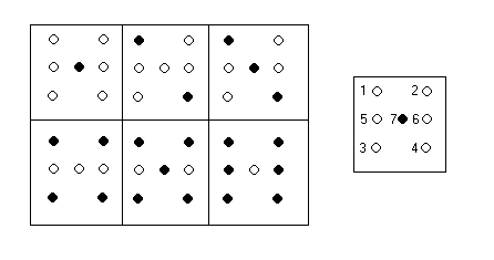
Lets look at a good old-fashioned dice. As we all know, it has 6 sides, and if we analyse the various dot patterns in Figure 1 below, we can see that the following rules apply;
- Opposing Corner dots (1) and (3) appear simultaneously.
- Opposing Corner dots (2) and (4) appear simultaneously.
- Middle dots (5) and (6) appear simultaneously.
- The Central dot (7) operates independently.
Driving LEDS Using a Microprocessor
The value of the current limiting resistor can be determined by using the equation;
Rser = (Vcc – VLed) / Iled
Where;
Rser Value of series resistor
Vcc Supply Voltage (5V)
VLed Forward voltage drop of the LED (typically 1.2V)
Iled Led Current (Typically 20mA)
So, for the single LED in the dice pattern, we need;
Rser = ( 5 - 1.2 ) / 20*10-3 = 220R.
And in the case of our dual LEDs, Rser becomes;
Rser = (5 - 2*1.2) / 20*10-3 = 100R.
Input Circuit - a Button to Do Things!
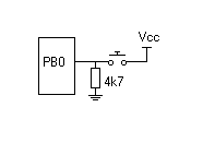
A single push button interface into a PIC can be implemented simply by connecting a push button between the supply voltage, (VCC) and an input that provides an interrupt capability (We’ll look at interrupts later). The figure below provides an example. Note that the input is held ‘low’ by a 4k7 resistor to ensure that random noise picked up on the input pin does not cause an input to be recorded.
The software can do many things with a single button. In this case, the button will do the following;- Turn the project on - if it is currently off
- Display the last thrown dice pattern - if pressed for less than 1 second
- Roll the dice - If held down.
Clock and Power Supply
Now that we have designed the inputs and the outputs, all that remains is to implement a power supply, and supply some sort of clock circuit to the microprocessor.
The most simple power supply we can have is to simply use 4 ‘AA’ batteries. This provides 6.0V. If a series reverse polarity protection diode is used, the available supply voltage drops to approx 5.4 Volts, which is within the PIC’s rated input voltage range of 4.0 – 6.0 volts.
Traditionally, microprocessor systems have used some sort of 3 terminal voltage regulator to ensure that 5.0 volts is available to the CPU. We decided not to use a 78L05 or similar 3 terminal voltage regulator, as the 4mA stand by current drawn by the regulator would swamp the sleep current of the PIC (approx 7uA), and would cause poor battery life.
In our circuit, the microprocessor consumes approximately 7uA while it is in its standby ‘sleep’ mode. So in theory, a set of 4 ‘AA’ alkaline batteries with a capacity of approximately 800mA/H should be able to last about 114,000 hours (13 years… I suspect that the batteries will die of their own accord LONG before this time !!) while in sleep mode. Of course, current consumption will increase to about 120mA during operation. As an aside - the project is STILL USING the same batteries I put in it in the year 2000 - And they haven't started leaking.
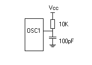
The PIC range of microprocessors can use a variety of clock circuits, ranging from crystal controlled oscillators, through to RC (resistor/capacitor) networks. If accurate timing is required, a crystal oscillator is recommended. In our application, we are not concerned about speed and clock accuracy, so we will use a RC oscillator for this design.
Our RC Oscillator is implemented by using a 10K resistor and a 1000pF Capacitor as shown in the following diagram; (note the the cap in the diagram is wrong - it should read 1000pf)
The Software Design
That’s it for the hardware design, now we need to design the software that will let our hardware become a dice.
One thing that you probably noticed was that the hardware implementation was done in a structured, building block manner. We need to approach our software design in the same way.
In designing our software, lets start by dividing the system into functional blocks. One easy division is to divide the problem into an input (The Button), some processing (actually rolling the dice), and an output (The LEDs).
Lets start by building the output part of our code first. It is the most visual component, and it lets us ‘put some runs on the board’ early. Before we start though, lets talk a little bit about the microprocessor instruction set, and the architecture.
The PIC range of microprocessors implement a Reduced Instruction Set Computer (RISC). Having a RISC core is one factor that makes these CPU’s so fast. A disadvantage of having a RISC core is that the PIC range of microprocessors only implement approximately 37 instructions, so it occasionally takes more instructions to do things, and often solutions don’t always appear to be as intuitive as they are on, for example, a Z80 or 6502.
In the PIC, the primary working register is the ‘W’ register. Most of our operations use the ‘W’ register in some way. Take, for example, a set of commands that will output a binary pattern ‘10101010’ to Port B.
MOVLW B’10101010’
MOVWF PortB
First, the word that we want to write is loaded into the ‘W’ register, then the ‘W’ register is written to Port B.
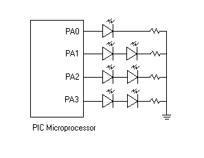
We can use this sequence of operations to output the bit pattern to display a dice roll of 6. From the schematic diagram, we can see that the first die is attached to Port A, bits 0 – 3 in the following way;
Port A(0) - Centre LED
Port A(1) - Corner LEDs (1) and (3).
Port A(2) - Corner LEDs (2) and (4).
Port A(3) - Middle LEDs (5) and (6).
To display the pattern for a 6, all corner LEDs, and all middle LEDs are on, but the centre LED is off. This equates to bit pattern of b’00001110’. So, to display a 6, we simply execute the instructions;
MOVLW B’00001110’
MOVWF PortA
Similarly, to display a 1 (the centre LED), we would use;
MOVLW B’00000001’
MOVWF PortA
We have been referring to 6 as 00001110, and 1 as 00000001. It can be confusing to use numbers like this, especially when they are not really numbers, they are simply bit patterns. To ease the confusion, most assemblers allow the use of ‘Constants’ to provide a mapping between a text name, and a number. In the case of our dice display, we can use the word Die6 in place of 00001110, or Die1 in place of 00000001.
A list of constants that we would be able to use in our display would be;
Die1 B’00000001’
Die2 B’00000100’
Die3 B’00000101’
Die4 B’00000110’
Die5 B’00000111’
Die6 B’00001110’
DieOff B’00000000’
DieTest B’00001111’
The last 2 entries (DieOff and DieTest) are useful for turning off the display, or verifying that all LEDs are operational at start up by turning all LEDs on.
Now that we know how to display a number, we should produce the building block that allows us to supply a number, and the appropriate bit pattern is loaded into the display.
Before we discuss this display routine, it should be mentioned that software is best written in a modular fashion, one routine at a time. This allows functionality to be added component by component. We can then concentrate on writing each component individually, allowing complex software to be built layer by layer.
Back to our building block for displaying a dice roll. A routine to implement the display functionality could look like this;
| ; First, define the required constants…. Die1 EQU B’00000001’ ; some constants are defined Die2 EQU B’00000100’ ; for the various LED DICE Die3 EQU B’00000101’ ; bit patterns Die4 EQU B’00000110’ Die5 EQU B’00000111’ Die6 EQU B’00001110’ DieOff EQU B’00000000’ ; ALL LEDs OFF DieTest EQU B’00001111’ ; ALL LEDs ON ; Disp_Dice1 - Causes a particular number to be displayed on a dice face ; Input: Register W ; Output: A LED Pattern on the dice. ; Comments: For the values of register ‘W’ ; 0 = All LEDs off ; 1 – 6 = display the pattern for 1 – 6 ; 7 = All LEDs ON (Test mode) ; DISP_DICEA CALL DIE_LOOKUP MOVWF PortA RETURN ; This is a branching lookup table. Basically, whatever value is passed in via the W register is ; added to the program counter (PCL). This then results in the appropriate value for the ; lookup result being loaded into the W register, and control being returned to the calling ; sub routine. ; ie; if a 2 is passed in through the W register, the ADDWF PCL,f operation causes 2 to be ; added to the current program counter causing the RETLW Die2 instruction to be executed. ; This results in the constant Die2 (B’00000100’) to be loaded into the W register, and ; control being returned to the calling program. DIE_LOOKUP ADDWF PCL, f RETLW DieOff RETLW Die1 RETLW Die2 RETLW Die3 RETLW Die4 RETLW Die5 RETLW Die6 RETLW DieTest |
Most of the above listing is comments ( lines preceded by the ‘;’ character), so it should be able to be followed.
The display routine can be used by executing the following code;
MOVLW 4
CALL DISP_DICEA
Interrupts to Save Energy
As previously mentioned, the microprocessor will be spending most of it’s time in sleep mode. (Especially while it is sitting majestically on the mantelpiece!). In sleep mode, the internal oscillator is stopped, and the device basically consumes no current.
In order to wake up from sleep mode, we need to have an ‘interrupt’ occur. Interrupts can be caused from a variety of sources, but they always signal some external change.
The LED Dice project that we are building has the pushbutton connected to bit 1 of Port B (PB0). This pin is also functions as an ‘interrupt’ input. When the voltage level on this pin changes, an interrupt is generated, causing the PIC to stop whatever it was doing, and to do something else. It is this interrupt that causes the PIC to wake up from it’s sleep mode.
Interrupts in the PIC can be ‘global’ in nature (Global Interrupt Enable [GIE] bit set), or localised. In our example, we would like to continue executing instructions immediately following the ‘sleep’ command, so we need to ensure that the GIE bit is clear. Global interrupts cause program execution to branch to location 4, which is useful for a more traditional vectored interrupt approach which we will cover in later articles.
Code to implement the interrupt functionality would look like;
|
MAINLOOP MOVFW PortB ; do a dummy read on port B MOVLW B’0010000’ ; Leave the GIE bit off, and enable the ; PB0 Interrupt bit MOVWF INTCON ; and load up the Interrupt control register SLEEP ; wait quietly for an interrupt….. MOVLW B’00000000’ ; disable interrupts. MOVWF INTCON ; Continue code execution (where we wait for the button to be released… ; ; ; ; eventualy, we goto MAINLOOP, where we do it all again.. |
One thing to note is that once we have received an interrupt, we wake, and immediately disable any further interrupts. Just with us humans, there is nothing more irritating that being interrupted while you have been interrupted. Multiple levels of interrupts can cause unexpected program errors, so we stop any further interrupts from occurring.
Now that we have examined how to implement input, output, random number generation and interrupts, we can tie all of this together, and produce the code that will actually run the dice.
There is a small amount of ‘glue’ around these functions to produce actual running code. I recommend that you obtain the program listings, and study them for more information.
If you do study the listings, you may find that there are faster, more elegant ways to do what has been done. Remember that there are commercial realities as to the time spent on producing a particular solution, and that some times, doing something the ‘no brain’, long way is actually faster to develop. This is an embedded system, and in a simple system like this, the emphasis is on producing a result, not on producing the most elegant code available. (Have you actually looked at the code in your microwave oven controller…)
Generating Random Numbers
Now that we can output data onto an individual LED Dice display, we need some way of generating a random number.
Mathematically, generating a truly random number is a very complex exercise. In our simple PIC circuit, we can generate a random number by a couple of means;
- A seemingly random number can be obtained by timing how long the button is held down, using a timer that incremented VERY quickly. (It would be a very rare person who could hold the button down for exactly 2243 mS every time).
- Alternately, we could implement a mathematical pseudo-random number generator. This requires the use of multiplication and division. A pseudo-random generator generates a very long sequence of numbers that eventually repeats, after many cycles.
In our project, the easiest method that we can use to generate a random number is to sample the internal timer (TMR0), which is constantly incrementing at ¼ of the clock speed (about 256KHz), and store it in a variable continuously, as long as the button is held down.
Our PIC 16F84 or 16F88 microprocessor has 68 memory locations that are able to be used as variables. To define a variable, we simply declare a constant that refers to a particular memory location, and store numbers in that memory location as required.
A short code routine to perform this function would be as follows;
| ; a memory location to store our random number RandomA EQU 30 ; define memory address to ; store a random number Button_Loop MOVFW TMR0 ; get the current timer value MOVWF RandomA ; store it in RandomA BTFSS PortB, 0 ; Is the button still down? GOTO Roll_Down ; no, jump out and slow ; down the display CALL Display_Result ; Yes,display the current roll CALL Short_Delay ; wait a while CLRF DieA ; clear both dice again CLRF DieB GOTO Button_Loop ; and loop again. Roll_Down: ; the rest of the program goes here. ; RandomA contains a number that has been randomly selected ; dependant on how long the button has been held down. |
Programming the PIC
To make the LED Dice operate you need to program the LED Dice program into a PIC. You can either purchase a Pre-Programmed PIC or you can program one yourself. Programming one yourself allows you to enter the world of PIC software design.
In order to program the PIC, you need some basic tools;
Firstly, you need the Microchip assembler and simulator (MPLAB), available as a 9Mb download from the microchip web site (http://www.microchip.com). This is a HUGE download, but you only need it once. (Remember to make a backup)
In addition to the assembler, you need a programmer. I have made several programmers over the years from various designs on the web.
Initially, I had a significant amount of trouble getting the published programmer to operate, so I built the NOPPP-2 (Experimental) version that used a 74HC08 in place of the diode logic that was present in the initial version. It worked flawlessly.
Once you have the tools, you need to create a .hex file to feed to the programmer. Start by loading up the MPLAB software, and creating a project by selecting ‘Project’, ‘New Project’ from the menu and typing the name of the project (Led Dice) into the file name box, ensuring that the default directory is in a reasonable location for your system. You need to add a source (.asm) file by clicking on the ‘Add files’ button in the ‘Edit Project’ menu.
Now that the project has a source file associated with it, you can assemble it by pressing F10. The build process will start, and a .hex file will be produced in the default directory specified above.
Once the program has been assembled, exit the MPLAB environment, and start the programmer (noppp). Specify the type of PIC (16F84), and load the .hex file. Insert the PIC into the programmer, and select Program. The PIC will be programmed in about 6 seconds. Exit the programmer, and remove the PIC from the socket.
Construction

The prototype was built using a strip of Veroboard®. This allowed a fast development time to be achieved on the hardware (about 1 hour). If you use Veroboard®, be very careful to support the board while cutting the hole for the pushbutton switch, otherwise, the board will snap in half.
The board is designed to mount on the top of a medium sized zippy box. This is to allow the simplicity of the circuit to be displayed to any curious office staff who have built a competing dice. If desired, the project can be mounted inside a slightly larger case, with the LEDs and push button mounted in the lid in a more conventional manner.
After the Veroboard is cut to size, ensure that it fits snugly in the lid of the zippy box. File the edges if the board is slightly too large. Now is also a good time to ensure that the push button fits snugly in the hole in the board. Use a small needle file to enlarge the hole if required.
Start assembly by installing the passive components first, such as the resistors and capacitors. You may find that it is beneficial to measure the values of the resistors with a multimeter to minimise errors. When bending component leads, remember that using a pair of needle nose pliers will minimise stress while performing the bend.
Continue assembly by soldering in the 18-pin IC socket, ensuring that the indentation on the socket is at the top of the PCB. Next, solder in the 14 LEDs. Be careful with their orientation, as they will not operate if they are installed backwards. The short leg is the cathode.
Mount the push button, and connect it to the PCB with 2 short (25mm) lengths of wire. Finally, connect the battery holder, ensuring that the batteries are not installed.
Examine the board for shorts caused during assembly, and install the batteries.
Verify that +6 volts is present on pin 14, and pin 4 (With respect to pin 5 [GND]).
Finally remove the batteries, install the pre-programmed PIC (16F84), and re-install the batteries. (Don’t insert the PIC with the power applied!!) You should be rewarded with a self test pattern.
Verify that the unit operates when the button is pressed as described earlier in this article. When you release the button, the display should ‘slow down’ and display the result for 50 seconds before turning off. Quickly touching the pushbutton should recall the last roll.
If the unit operates correctly, carefully mount the PCB in the top of the zippy box.
You may like to install a small piece of Perspex™ sheeting over the top of the project to protect it from small prying fingers. This can be mounted on 12mm brass standoffs on the top of the PCB, with a small hole placed over the pushbutton.
All that remains now is to instruct the kids on how to operate it, and to chain it to the table so that it doesn’t end up at the bottom of the toy box, which incidentally is where the 265 other dice went.
Have fun. And remember, unless you create some code to allow you to cheat, it is very hard to force the dice to roll a particular way. Remember also that the one disadvantage of this project over the real dice is that it isn’t built to survive 20G’s of deceleration, so throwing it would be bad.
Troubleshooting
If for some reason the project fails to work, check all soldering carefully. Verify that all the LEDs have been installed correctly. You can check the hardware by removing the PIC, and placing a 10R resistor between pin 14 (VCC) and each of the LED drive lines (Pins 1,2,10,11,12,13,17, and 18) one at a time. The LEDs should light.
You can verify the push button operates by monitoring pin 6 with a logic probe, or multimeter while pushing the button. It should go to +6V when the button is down.
Finally, if you have a CRO, you can verify that the internal PIC oscillator is running by examining pin 15 (CLKOUT). You should see a 1MHz square wave for 3 seconds after the device is powered up, and for 3 seconds after the button is pressed.
If all of the hardware checks out, you should try re-programming the PIC. Perhaps it has the wrong code installed.
Good Luck. And remember that this is supposed to be fun!
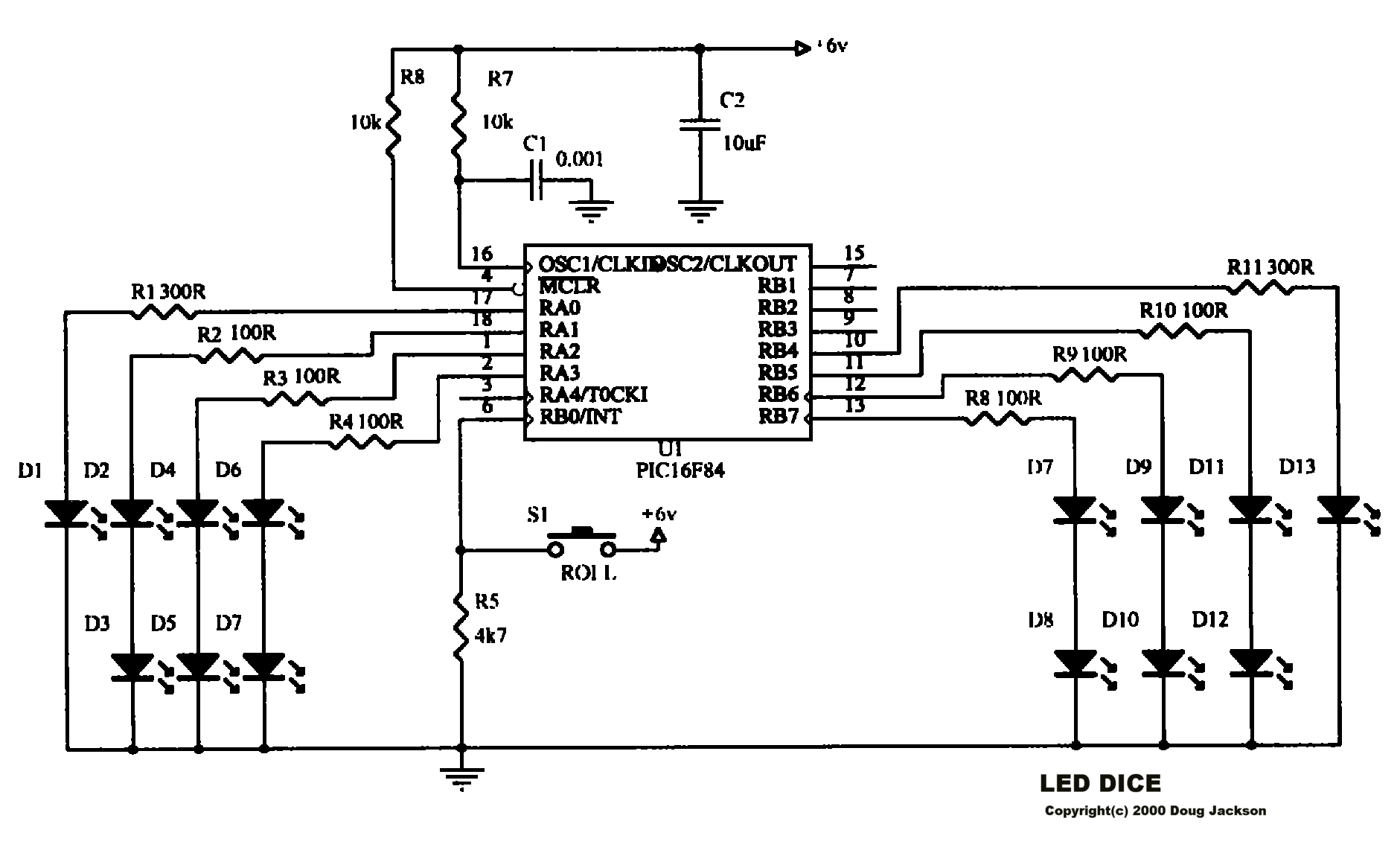
The Completed Circuit Diagram and Code for the Microcontroller
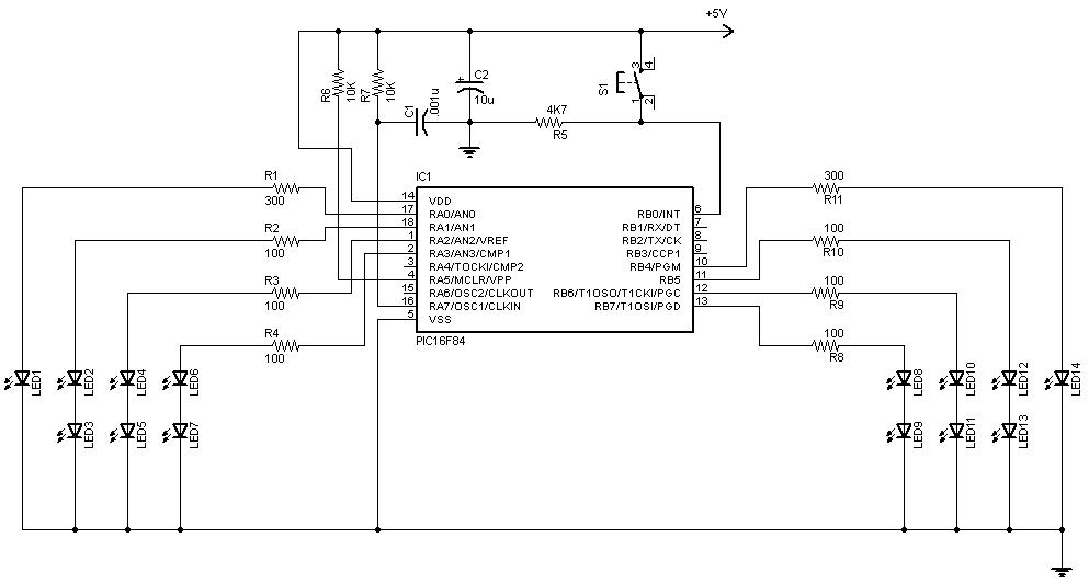
Many thanks to "jman 31' who redrew the schematic to fix some irritating errors. :-)
The Hardware - Other Ways of Making It
I have seen others use point to point wiring as well.
Here are some links to some others who have built the project using an IC socket, and directly soldering components to the socket. They have liberally used hot glue to make the project more robust. I thought these were excellent solutions. The important thing is to have an attitude of getting in there and just making it!
Have a go, and have fun!
https://www.instructables.com/id/Led_Dice_PIC16F84/
https://www.instructables.com/id/Led_Dice_PIC16F84_in_Box/