Angle Based Height & Distance Measurement Device
by HCN1999 in Circuits > Arduino
1308 Views, 1 Favorites, 0 Comments
Angle Based Height & Distance Measurement Device
.jpg)
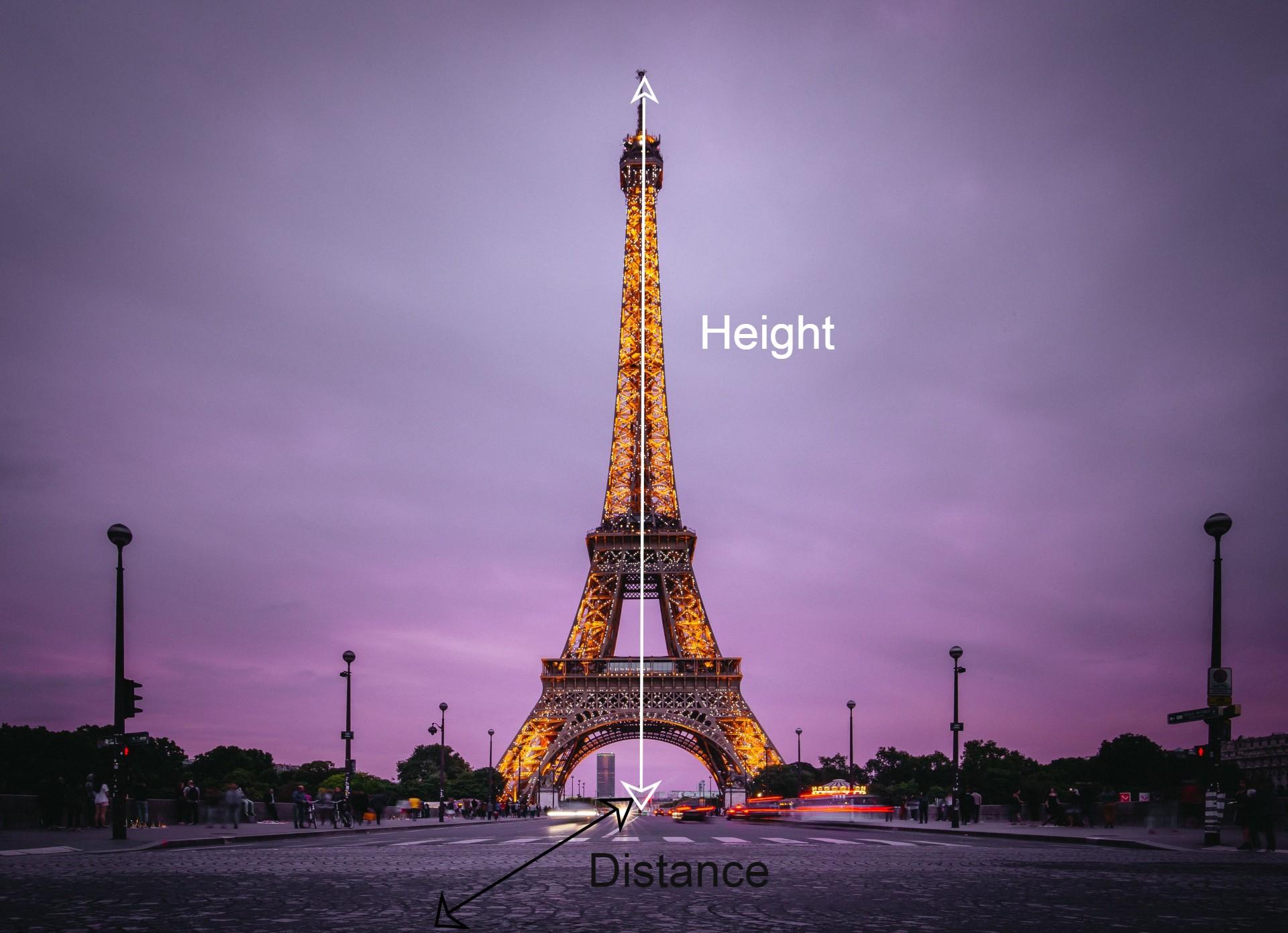
Ever wondered about the height of or distance to a specific object or nearby place ?? Then this instructable is for you. This is a simple project that make use of trigonometry to find the distance to / height of objects.
Supplies
Hardware Used:
- Arduino Nano (3.3V , 8MHz version)
- MPU6050 Accelerometer Module
- Ultrasonic Sensor
- OLED Screen (0.96" 128x64 display )
- Momentary Button x 4 (There is a whole lot of them ,I can't find which one I used)
- Perfboard x 2
- Diode x 4 (1N4148)
- Resistor (220 ohms)
- Wire
- 18650 Li-ion battery (3.7 V 2500mAh)
- Battery Holder
- Sliding switch
Software Used:
- Arduino IDE
Tools:
- Soldering Iron
- Hacksaw blade
- Sanding paper
- Scissors
- Adhesive (I used flex kwik)
For Frame (optional):
- HDF sheets (high density fiberboard)
- Spoon bowls (for making a stand for the device)
The Idea


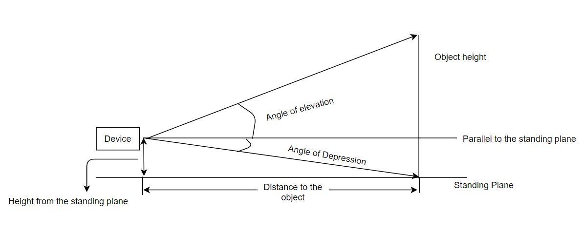

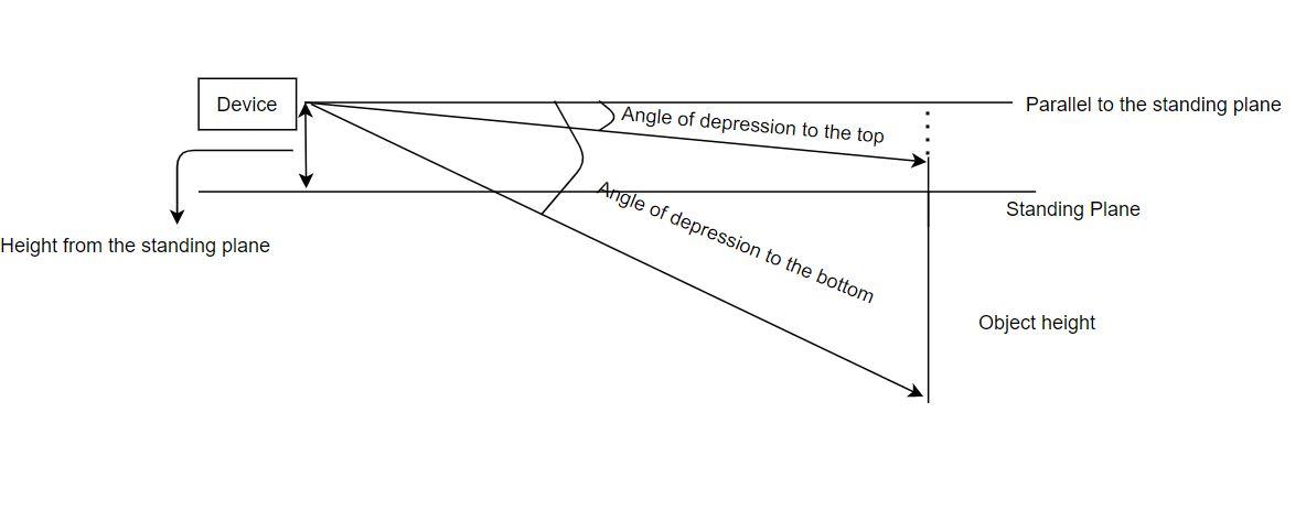
Let's start from the basics. Math haters can just ignore this step :)
Here are some terms that you will find more in this instructable:
- Angle of Elevation: The angle between the horizontal and the line of sight from the observer to some point of interest. This angle is above the horizontal line.
- Angle of Depression: This also has the same definition as angle of elevation but it is on the opposite side( that is, below the horizontal line).
Now, in order to find the distance we need to do some trigonometry.
Height from the plane = tan(angle of depression) x distance to point of interest
If we can find the height from the plane and the angle of depression we can obtain the distance to the point we desire.
In the case of height , it is a bit more complicated as there are different ways in an object can be, relative to the device
1. Top of the object above the horizontal and Bottom of the object below the horizontal: We need to find distance as in the previous method and then,
Height of the object = distance x (tan(angle of elevation to the top) + tan(angle of depression to the bottom))
2. Top of the object above the horizontal and Bottom of the object also above the horizontal: We need to find distance as in the previous method and then,
Height of the object = distance x (tan(angle of elevation to the top) - tan(angle of elevation to the bottom))
3. Top of the object above the horizontal and Bottom of the object below the horizontal: We need to find distance as in the previous method and then,
Height of the object = distance x (tan(angle of depression to the top) - tan(angle of depression to the bottom))
Note that horizontal is with respect to the device and will depend on the calibration(discussed in later steps) distance in all the above equations refers to the distance between the device and object measured parallel to the horizontal. Please have a look at the pictures if you have a doubt.
Standing plane: The plane where user stands.
The Workflow

The basic working flow :
- CALIBRATION: The user might not be standing on a horizontal plane and hence, we need to adjust the values according to that. This step takes the accelerometer values and finds out the angle from the actual horizontal. The device should be positioned in a certain way for an accurate calibration. This value is taken as a standard and the future calculations all depend on this value. Calibration is required on every startup.
- MODES: The device work in two ways:
- Height Mode: This mode is used for finding heights. This is a three step process:
- User is prompted to point at the extrapolated base (or top) point coincident with the same plane as user and the corresponding angle is measured.(See the images)
- Then user is required to point to the top of the object and the angle is measured.
- Finally the angle to the bottom is also measured by prompting the user to point at the base of the object. All these angles are used to find the height of the object.
- Distance Mode: This is a distance estimator mode. Here the user needs to point at the extrapolated base (or top) point coincident with the same plane as user and the distance can be calculated.
- Distance/Height (for small dimensions): The device has an onboard ultrasonic sensor and distance up to 4m can be measured using this. But that's not the whole point of the device but indeed it comes as an additional feature :)
- Height Mode: This mode is used for finding heights. This is a three step process:
- DISTANCE TO THE PLANE CALCULATION: If you have seen the images, it is clear that we need height from the standing plane in order to calculate both the distance and the height. This is where the ultrasonic sensor is put to use. The ultrasonic sensor finds the height of the device from the ground and use it for calculation. But in some cases, the user might already know the height from the base (or even ultrasonic sensor running out of range) and a provision is made to add the height manually .
-
RESULT: The result is calculated by arduino and then displayed on the OLED screen.
Hardware: Components
This step might seem irrelevant or repetitive. But I do feel the necessity of this step. Bear with me!!
- Arduino Nano : The heart of the project, where all the calculation is done. It also takes the value from ultrasonic sensor and has an I2C bus to control OLED and MPU6050 accelerometer. The interrupt pin is also used by the push buttons (for user inputs). The angle calculation is also done on arduino from the raw acceleration values from the accelerometer.
- MPU6050 Accelerometer Module: All the acceleration values are obtained using this module. The values are raw and are needed to be converted before using them.
- Ultrasonic Sensor: Used to measure the distance between device and standing plane.
- OLED Display: It provides a user interface and also aid in displaying results.
- Button: All the user inputs are obtained using the buttons.
- Power Source: 18650 battery (3.7V 2000mAh) is used as the power source.
Since arduino pro mini only has two interrupt pins, and 4 buttons are needed to be controlled, the workaround was to use diodes and resistors in such a way that the interrupt get triggered if any switch is pressed and the digital level (HIGH or LOW) is measured at each pin to identify the button pressed.
Hardware: Circuit Diagram

In case the above circuit is not clear, take a look at the textfile. Also I missed the sliding switch in the diagram. It should be added in between the power source and the device circuit and act as a simple on-off switch.
Downloads
Hardware: PerfBoard Assembly (Switches)
.jpg)
.jpg)
.jpg)
I wanted four keys; each for up, down, ok and cancel. For this purpose, I split one perfboard into two. The switches were taken out from a key fob and hence it's legs were small. So I had to solder it on the soldering side of the perfboard.
Hardware: PerfBoard Assembly (MPU6050, Ultrasonic Sensor and OLED Screen)
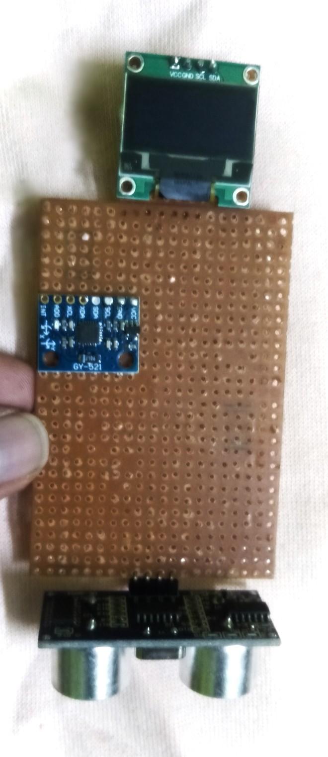.jpg)
.jpg)

I added common ground and power pads so that adding wires become more easier (The image here shows incomplete padding). Also as the ultrasonic sensor was used to measure the height to the standing plane, it had to be at the bottom facing vertically downwards. The OLED Screen was initially soldered to another perfboard piece and then fixed to the main perfboard.
Hardware: PerfBoard Assembly (Diodes and Resistors)

You can see that I placed components on both sides of the perfboard. This is not a good practice and becomes very messy. But in my case, the diodes were salvaged from a rectifier and did not had enough length to put it on the other side (so that legs can be soldered on the other side).
Hardware: PerfBoard Assembly (Arduino)
.jpg)
Putting arduino was the most difficult task. To reduce the wire crossings I had to put it at a central position. To add to the difficulty, pins were already soldered on to the board ( this was a pretty old pro mini ). So I had to take the wires over the board to solder them
Software: Code
These are the required libraries for our project. Download these from here.
#include <Wire.h>
#include <Adafruit_GFX.h>
#include <Adafruit_SSD1306.h>
#include <Math.h>
Now we define all the keys and constants.
// Arrow Key declaration
#define UP_ARROW 7
#define DOWN_ARROW 9
#define OK_ARROW 8
#define CANCEL_ARROW 4

//Interrupt for key presses
#define INTERRUPT_PIN 3

//Ultrasonic sensor pins
#define echoPin 6
#define trigPin 5

//Screen Dimensions
#define SCREEN_WIDTH 128
#define SCREEN_HEIGHT 32

#define OLED_RESET  -1
Adafruit_SSD1306 display(SCREEN_WIDTH, SCREEN_HEIGHT, &Wire, OLED_RESET);
All variables are defined here.
const int MPU_addr=0x68;
float axis_X,axis_Y,axis_Z;
float default_Z;

int screenno = 1;//corresponds to different menu screens


double z;

//The variables for ISR function
volatile boolean up = false;
volatile boolean down = false;
volatile boolean ok = false;
volatile boolean back = false;

boolean tryagain = true;


float default_angle;
long start;
The setup() function. The pins are defined, interrupt is attached and the sensors are initialized in this part. Calibration is also done here.
  Serial.begin(9600);

  pinMode(trigPin, OUTPUT); // Sets the trigPin as an OUTPUT
  pinMode(echoPin, INPUT);// Sets the trigPin as an INPUT

  //Setting up all the arrow keys
  pinMode(UP_ARROW, INPUT_PULLUP);
  pinMode(DOWN_ARROW, INPUT_PULLUP);
  pinMode(OK_ARROW, INPUT_PULLUP);
  pinMode(CANCEL_ARROW, INPUT_PULLUP);
  pinMode(INTERRUPT_PIN, INPUT_PULLUP);

  //Attaching the Interrupt
  attachInterrupt(digitalPinToInterrupt(INTERRUPT_PIN),keycheck , FALLING);

  if(!display.begin(SSD1306_SWITCHCAPVCC, 0x3C)){//0x3C is the address for 128x32
    Serial.println("Display failed");
  }
  delay(1000);

  //Setting up a welcome screen
  display.clearDisplay();
  display.setTextSize(1);
  display.setTextColor(WHITE);
  display.setCursor(50,10);
  display.println("Welcome");
  display.display();
  delay(5000);

  //Initializing MPU6050
  Wire.begin();
  Wire.beginTransmission(MPU_addr);
  Wire.write(0x6B);
  Wire.write(0);
  Wire.endTransmission(true);

  display.clearDisplay();
  display.setCursor(40,10);
  display.println("Initializing....");
  display.display();
  delay(3000);
  display.clearDisplay();
  display.setTextSize(1);
  display.setTextColor(WHITE);
  display.setCursor(50,10);
  display.println("Done!!");
  Serial.println("Done!!");
  display.display();
  delay(1000);

  //Calibrating part
  display.clearDisplay();
  display.setTextSize(1);
  display.setTextColor(WHITE);
  display.setCursor(0,0);
  display.println("Place the unit on the ground and press OK");
  Serial.println("Place the unit on the ground and press OK");
  display.display();
  while(!ok){//Waiting for ok button to be pressed
    delay(500);
  }
  Serial.println("OK True");
  ok = false;
  int y =0;
  display.clearDisplay();
  display.setCursor(30,10);
  display.setTextSize(1);
  display.setTextColor(WHITE);
  display.println("Calibrating...");
  display.display();
  default_angle = getangle();
  default_Z = axis_X;
  // We convert angle from the x-y plane to z-x plane
  if(default_Z < 0)
    default_angle = 90 - default_angle;
  else
    default_angle = default_angle + 90;
  Serial.print("Angle of inclination in Z axis= ");
  Serial.print(default_angle);
  delay(500);
  Wire.endTransmission(true);
  if(!display.begin(SSD1306_SWITCHCAPVCC, 0x3C)){//0x3C is the address for 128x32
    Serial.println("Display failed");
  }
  display.clearDisplay();
  display.setTextSize(1);
  display.setTextColor(WHITE);
  display.setCursor(20,10);
  display.println("Calibration Done!!");
  Serial.println("Calibration Done!!");
  display.display();
  delay(2000);
The loop function;it constantly checks for which screen on menu is chosen.
while(tryagain){
  float height;
  int j = 0;  // j stands for the mode selected
  Serial.println("Insideloop");
  if(screenno ==1 ){

  display.clearDisplay();
  display.setTextSize(1);
  display.setTextColor(WHITE);
  display.setCursor(0,0);
  display.println(">");
  display.setCursor(10,0);
  display.println("Measure Height");
  display.setCursor(10,10);
  display.println("Measure Distance");
  display.setCursor(10,25);
  display.println("Cancel");
  display.setCursor(90,25);
  display.println("Ok");
  display.display();
  while(screenno ==1){
  while(!ok && !back && !up && !down){//Waiting for a button to be pressed
    delay(10);
  }
  if(ok){ //jumping to next screen
    ok = false;
    screenno = 2;
  }
  else if(up){
    up = false;
    if(j==1){
      display.clearDisplay();
      display.setTextSize(1);
      display.setTextColor(WHITE);
      display.setCursor(0,0);
      display.println(">");
      display.setCursor(10,0);
      display.println("Measure Height");
      display.setCursor(10,10);
      display.println("Measure Distance");
      display.setCursor(10,25);
      display.println("Cancel");
      display.setCursor(90,25);
      display.println("Ok");
      display.display();
      display.display();
      j =0;
    }
  }
  else if(down){
    down = false;
    if(j==0){
      display.clearDisplay();
      display.setTextSize(1);
      display.setTextColor(WHITE);
      display.setCursor(0,10);
      display.println(">");
      display.setCursor(10,0);
      display.println("Measure Height");
      display.setCursor(10,10);
      display.println("Measure Distance");
      display.setCursor(10,25);
      display.println("Cancel");
      display.setCursor(90,25);
      display.println("Ok");
      display.display();
      display.display();
      j =0;
      j =1;
    }
  }
  }}
    if(screenno == 2){
      int k = 0; // k stande for automatic and manual modes
  display.clearDisplay();
  display.setTextSize(1);
  display.setTextColor(WHITE);
  display.setCursor(30,0);
  display.println("Height Mode");
  display.setCursor(0,10);
  display.println(">");
  display.setCursor(10,10);
  display.println("Automatic");
  display.setCursor(10,18);
  display.println("Manual");
  display.setCursor(10,25);
  display.println("Cancel");
  display.setCursor(90,25);
  display.println("Ok");
  display.display();
  while(screenno ==2){
  while(!ok && !back && !up && !down){//Waiting for a button to be pressed
    delay(10);
  }
  if(ok){
    ok = false;
    if(k == 0)
      screenno = 3;
    if(k == 1)
      screenno = 4;
  }
  else if(up){
    up = false;
    if(k==1){
  display.clearDisplay();
  display.setTextSize(1);
  display.setTextColor(WHITE);
  display.setCursor(30,0);
  display.println("Height Mode");
  display.setCursor(0,10);
  display.println(">");
  display.setCursor(10,10);
  display.println("Automatic");
  display.setCursor(10,18);
  display.println("Manual");
  display.setCursor(10,25);
  display.println("Cancel");
  display.setCursor(90,25);
  display.println("Ok");
  display.display();
  k = 0;
    }
  }
  else if(down){
    down = false;
    if(k==0){
  display.clearDisplay();
  display.setTextSize(1);
  display.setTextColor(WHITE);
  display.setCursor(30,0);
  display.println("Height Mode");
  display.setCursor(0,18);
  display.println(">");
  display.setCursor(10,10);
  display.println("Automatic");
  display.setCursor(10,18);
  display.println("Manual");
  display.setCursor(10,25);
  display.println("Cancel");
  display.setCursor(90,25);
  display.println("Ok");
  display.display();
  k =1;
    }
  }
  else if(back){
    back = false;
    screenno =1;
  }
  }

  }
    if(screenno == 3){
  display.clearDisplay();
  display.setTextSize(1);
  display.setTextColor(WHITE);
  display.setCursor(20,5);
  display.println("Height:");
  display.setCursor(60,5);
  height = getheight();
  height = height + 5;// 5 is the distance between ultrasonic sensor and accelerometer
  display.println(height);
  display.setCursor(100,5);
  display.println("cm");
  display.setTextSize(1);
  display.setCursor(10,25);
  display.println("Cancel");
  display.setCursor(90,25);
  display.println("Ok");

  display.display();
  while(screenno ==3){
  while(!ok && !back && !up && !down){//Waiting for a button to be pressed
    delay(10);
  }
  if(ok){
    ok = false;
    if(j == 0)
     screenno = 6;
    else if(j == 1)
      screenno = 5;
  }
  else if(back){
    back = false;
    screenno = 2;
  }
  }

  }
    if(screenno == 4){
  display.clearDisplay();
  display.setTextSize(1);
  display.setTextColor(WHITE);
  display.setCursor(50,0);
  display.println("Height");
  display.setCursor(45,10);
  display.println("0");
  display.setCursor(50,10);
  display.println(".");
  display.setCursor(55,10);
  display.println("0");
  display.setCursor(80,10);
  display.println("m");
  display.setCursor(10,20);
  display.println("Cancel");
  display.setCursor(80,20);
  display.println("Ok");
  display.display();
  int i =0; //the first digit ('a') in a.b cm
  int s = 0;//the second digit ('b') in a.b cm
  int t = 0;
  int m = 0;//number that represents the unit selected
  while(screenno ==4){
  while(!ok && !back && !up && !down){
    delay(10);
  }

  if(ok){
    ok = false;
    // converting all readings to centimeters
    if(j == 0 && t == 2){
      if(m == -1){
        height = i + s*0.01 + 5;
        screenno = 6;}
      else if(m == 0){
        height = i + s*0.01;
        height = height*100 + 5;
        screenno = 6;}
       else if(m == 1){
        height = i + s*0.01;
        height = height*100000 + 5;
        screenno = 6;} }
    if(j == 1 && t == 2)
       if(m == -1){
        height = i + s*0.01 + 5;
        screenno = 5;}
      else if(m == 0){
        height = i + s*0.01;
        height = height*100 + 5;
        screenno = 5;}
       else if(m == 1){
        height = i + s*0.01;
        height = height*100000 + 5;
        screenno = 5;}
    if(t == 1)
      t =2;
    if(t == 0)
      t =1;
  }
  else if(up){
    up = false;
    if(t == 0){
      i++;
      heightdisp(i,s,m);
    }
    else if(t == 1){
      s++;
      heightdisp(i,s,m);
    }
    else if(t == 2){
      if(m == 0){
       m =1;
       heightdisp(i,s,m);}
      else if(m == -1){
        m =1;
       heightdisp(i,s,m);
      }

    }
  }
  else if(down){
    down = false;
      if(t == 0){
      if(i > 0)
         i--;
      heightdisp(i,s,m);
    }
    else if(t == 1){
      if(s > 0)
         s--;
      heightdisp(i,s,m);
    }
      else if(t == 2){
       if(m == 1){
       m =0;
       heightdisp(i,s,m);}
      else if(m == 0){
        m =-1;
       heightdisp(i,s,m);
      }
    }
  }
  else if(back){
    back = false;
    if(t ==0)
      screenno = 2;
    else if (t == 1)
       t = 0;
    else if(t == 2)
      t =1;
  }
  }
  }
    if(screenno == 5){
  display.clearDisplay();
  display.setTextSize(1);
  display.setTextColor(WHITE);
  display.setCursor(10,0);
  display.println("Point to the plane coincident part of the object and press OK");
  display.display();
  while(!ok)
    delay(10);
  ok = false;
   display.clearDisplay();
  display.setTextSize(1);
  display.setTextColor(WHITE);
  display.setCursor(30,10);
  display.println("Calculating....");
  display.display();
  float angle = getangle();
  float height_Z = axis_Z;
  float dist;

  // This is a crucial part in the program. Have a look in the instructable for explanation
  if((height_Z > 0 && default_Z < 0) || (height_Z < 0 && default_Z > 0))
     dist = height/abs(tan((PI - default_angle - angle)*PI/180));
  else
     dist = height/abs(tan((default_angle - angle)*PI/180));
  display.clearDisplay();
  display.setTextSize(1);
  display.setTextColor(WHITE);
  display.setCursor(50,0);
  display.println("Distance");
  if(dist >= 0){
    display.setCursor(50,10);
    display.println(dist);
    Serial.println(dist);
    display.setTextSize(1);
    display.setCursor(105,10);
    display.println("cm");
    }
  else{
    display.setCursor(50,10);
    display.println("Error");
    delay(3000);
    screenno = 7;
  }
  display.setCursor(10,20);
  display.println("Cancel");
  display.setCursor(80,20);
  display.println("Ok");
  display.display();
  delay(2000);
  while(screenno == 5){
     while(!ok && !back && !up && !down){//Waiting for a button to be pressed
         delay(10);
         }
  if(ok){
    ok = false;
    screenno = 7;
      }
  else if(back){
    back = false;
    screenno = 5;
  }
  }

  }
 if(screenno == 6){
  Serial.println(ok);
  display.clearDisplay();
  display.setTextSize(1);
  display.setTextColor(WHITE);
  display.setCursor(10,0);
  display.println("Point to the plane coincident part of the object and press OK");
  display.display();
  Serial.println(ok);
  while(!ok){
    delay(50);
    }
  ok =false;
  display.clearDisplay();
  display.setTextSize(1);
  display.setTextColor(WHITE);
  display.setCursor(30,10);
  display.println("Calculating....");
  display.display();
  float angle = getangle();
  float height_Z = axis_Z;
  float dist;

  // This is a crucial part in the program. Have a look in the instructable for explanation
  if((height_Z > 0 && default_Z < 0) || (height_Z < 0 && default_Z > 0))
     dist = height/abs(tan((180 - default_angle - angle)*PI/180));
  else
     dist = height/abs(tan((default_angle - angle)*PI/180));
  Serial.println(dist);
   if(!display.begin(SSD1306_SWITCHCAPVCC, 0x3C)){//0x3C is the address for 128x32
    Serial.println("Display failed");
  }

/*This code is a slight modification so that user can point by adjusting
the device height from the standing plane while pointing to top or bottom */

  display.clearDisplay();
  display.setTextSize(1);
  display.setTextColor(WHITE);
  display.setCursor(10,0);
  display.println("Now hold the device vertically(at desired position) and press OK");
  display.display();
  while(!ok){
    delay(50);
    }
  ok = false;
  int h1 = getheight();
  delay(500);
  display.clearDisplay();
  display.setTextSize(1);
  display.setTextColor(WHITE);
  display.setCursor(10,0);
  display.println("Now point to the top of the object and press OK");
  display.display();
  while(!ok){
    delay(50);
    }
  ok =false;
  display.clearDisplay();
  display.setTextSize(1);
  display.setTextColor(WHITE);
  display.setCursor(30,10);
  display.println("Calculating....");
  display.display();
  float topangle = getangle();
  float top_Z = axis_Z;
  Serial.println(topangle);

/*This code is a slight modification so that user can point
 by adjusting the device height from the standing plane while pointing to top or bottom */

  display.clearDisplay();
  display.setTextSize(1);
  display.setTextColor(WHITE);
  display.setCursor(10,0);
  display.println("Now hold the device vertically(at desired position)  and press OK");
  display.display();
  while(!ok){
    delay(50);
    }
  ok = false;
  int h2 = getheight();
  delay(500);
  display.clearDisplay();
  display.setTextSize(1);
  display.setTextColor(WHITE);
  display.setCursor(10,0);
  display.println("Now point to the bottom of the object and press OK");
  display.display();
  while(!ok){
    delay(50);}
  ok =false;
  display.clearDisplay();
  display.setTextSize(1);
  display.setTextColor(WHITE);
  display.setCursor(30,10);
  display.println("Calculating....");
  display.display();
  float bottomangle = getangle();
  float bottom_Z = axis_Z;
  Serial.println(" ");
  Serial.println(top_Z);
  Serial.println(bottom_Z);
  Serial.println(default_Z);
  float ht;
  if(top_Z >= 0 && bottom_Z >=0){
     if(default_Z <= 0)
        ht = dist*tan(abs(180 - default_angle - bottomangle)*PI/180) - dist*tan(abs(180 - default_angle - topangle)*PI/180);
     else
        ht = dist*tan(abs(default_angle - bottomangle)*PI/180) - dist*tan(abs(default_angle - topangle)*PI/180);
  }
  else if(top_Z <= 0 && bottom_Z <=0){
     if(default_Z >= 0)
        ht = dist*tan(abs(180 - default_angle - topangle)*PI/180) - dist*tan(abs(180 - default_angle - bottomangle)*PI/180);
     else
        ht = dist*tan(abs(default_angle - topangle)*PI/180) - dist*tan(abs(default_angle - bottomangle)*PI/180);
  }
  else{
    if(default_Z <= 0)
     ht = dist*tan(abs(default_angle - bottomangle)*PI/180) + dist*tan(abs(180 - default_angle - topangle)*PI/180);
    else if(default_Z >= 0)
     ht = dist*tan(abs(180 - default_angle - bottomangle)*PI/180) + dist*tan(abs(default_angle - topangle)*PI/180);
  }
  ht = ht + abs(h1 - h2);
  Serial.println(ht);
  display.clearDisplay();
  display.setTextSize(1);
  display.setTextColor(WHITE);
  display.setCursor(20,0);
  display.println("Object Height");
  display.setCursor(50,10);
  if(ht >= 0){
    if(isnan(ht))
      display.println("0");
    else
      display.println(ht);
    display.setCursor(105,10);
    display.println("cm");}
  else{
    display.println("Error");

  }
  display.setTextSize(1);
  display.setCursor(80,20);
  display.println("Ok");
  display.display();
   while(screenno ==6){
  while(!ok && !back && !up && !down){//Waiting for a button to be pressed
    delay(10);
  }
  if(ok){

    ok = false;
    screenno = 7;
      }
  else if(back){
    back = false;
    screenno = 6;
  }
  }
  }
  if(screenno == 7){
  display.clearDisplay();
  display.setTextSize(1);
  display.setTextColor(WHITE);
  display.setCursor(30,10);
  display.println("TRY AGAIN??");
  display.setTextSize(1);
  display.setCursor(10,20);
  display.println("Cancel");
  display.setCursor(80,20);
  display.println("Ok");
  display.display();

  while(screenno ==7){
  while(!ok && !back && !up && !down){
    delay(10);
  }
  if(ok){
    Serial.println("Last");
    ok = false;
    tryagain = true;
    screenno = 1;

      }
  else if(back){
    back = false;
    display.clearDisplay();
  display.setTextSize(1);
  display.setTextColor(WHITE);
  display.setCursor(30,10);
  display.println("THANK YOU!!");
  display.display();
    tryagain = false;
    screenno =10;
  }
  }
}}
The keycheck() function (for checking which key is pressed)
void keycheck(){//ISR function to check which key was pressed
  if(millis() - start >300){
    Serial.println("Clicked");
    if(digitalRead(UP_ARROW) == LOW)
       up =true;
    else if(digitalRead(DOWN_ARROW) == LOW)
       down =true;
    else if(digitalRead(OK_ARROW) == LOW)
       ok =true;
    else if(digitalRead(CANCEL_ARROW) == LOW)
       back =true;
}
  start = millis();
}
The function that checks height to the standing plane using ultrasonic sensor
void getheight(){
  digitalWrite(trigPin, LOW);
  delayMicroseconds(2);

  // Sets the trigPin HIGH (ACTIVE) for 10 microseconds
  digitalWrite(trigPin, HIGH);
  delayMicroseconds(10);
  digitalWrite(trigPin, LOW);

  // Reads the echoPin, returns the sound wave travel time in microseconds
  long  duration = pulseIn(echoPin, HIGH);

  // Calculating the distance
  long distance = duration * 0.034 / 2;

  Serial.print("Distance: ");
  Serial.print(distance);
  Serial.println(" cm");
  return distance;
}
A function was also required to find the angle with the vertical axis. It takes the average of 150 values taken from the accelerometer and find the pitch angle
 void getangle(){
  int y =0;

  //taking accelerometer value from MPU6050
  Wire.begin();
  Wire.beginTransmission(MPU_addr);
  Wire.write(0x6B);
  Wire.write(0);
  Wire.endTransmission(true);

  //Averaging out acceleration value from 150 values
  for(int i = 0; i< 150;i++){
  Wire.beginTransmission(MPU_addr);
  Wire.write(0x3B);
  Wire.endTransmission(false);
  Wire.requestFrom(MPU_addr,6,true);
  axis_X = (Wire.read() << 8 | Wire.read()) / 16384.0; // X-axis value
  axis_Y = (Wire.read() << 8 | Wire.read()) / 16384.0; // Y-axis value
  axis_Z = (Wire.read() << 8 | Wire.read()) / 16384.0; // Z-axis value
  z= (atan(-1 * axis_X / sqrt(pow(axis_Y, 2) + pow(axis_Z, 2)))*180/PI) + 1.58;
  z = z + y;
  y = z;
  delay(50);
  }
  z = z/150;
  Serial.print("Angle of inclination in Z axis= ");
  Serial.print(z);
  Wire.endTransmission(true);
  delay(500);
  return z;
}
A manual height addition is also there. This function is needed to increase or decrease the heights, so that users can set a custom height
void heightdisp(int i,int s ,int m){//function for displaying height in manual mode
   display.clearDisplay();
  display.setTextSize(1);
  display.setTextColor(WHITE);
  display.setCursor(50,0);
  display.println("Height");
  display.setCursor(45,10);
  display.println(i);
  display.setCursor(50,10);
  display.println(".");
  display.setCursor(55,10);
  display.println(s);
  display.setCursor(80,10);
  if(m==0)
    display.println("m");
  if(m==1)
    display.println("km");
  if(m==-1)
    display.println("cm");
  display.setCursor(10,20);
  display.println("Cancel");
  display.setCursor(80,20);
  display.println("Ok");
  display.display();
}
Downloads
A Bit About Calibration
Let us again jump back to some math.
To find the correct distance/height it is necessary to have angle with great accuracy. So for instance, if you are standing on a slanted plane, your value is going to be different from that of some other planes. By calibration, we try to adjust the device angle to the standing plane angle and all other angle measured are from this adjusted angle.
STEPS FOR CALIBRATION:
The device should be placed on the ground and a button should be pressed.
By doing this, we are calculating the angle with the true vertical. An angle of 90 degree is needed to be added with (or subtracted from) this angle to get proper results. This is because all objects that we measure are vertical (or nearly vertical) from the plane and thus the angle should be measured from the horizontal line parallel to the standing plane.
Some Adjustments Made for Angle Calculation and Height Calculation


.jpg)
From the image, you can see all those random 180 degrees. This code snippet is from the height measuring part (or height mode). "top_Z" refers to Z acceleration when you point the device at the top of the object and "bottom_Z" refers to Z acceleration when you point the device at the bottom of the object and "default_Z" refers to X acceleration when you calibrate the device.The "top_angle"and "bottom_angle" refers to the corresponding angles. For "default_Z" we take the X acceleration because the calibration is done in a such a way that the device is placed on the ground. In the same way "default_angle" refers to the angle to the X axis(while calibration) + 90 degrees.
Now, if you are standing on a slanted plane, your calibration angle (default_angle) is going to be greater or less than the actual horizontal. Also if you look at second image, the angle is found out by inverse tangent (atan function) function, which gives you a value between -90 and 90 degrees. Hence we need to add (180 - default_angle - top_angle),etc. to get the correct result.
There is a slight offset between the ultrasonic sensor and accelerometer. This difference in height should be added to get an accurate result (for the height from the standing plane). In my case it was 5 cm.
Putting Together
.jpg)
.jpg)
.jpg)
.jpg)
.jpg)

.jpg)
Unfortunately, I do not have a 3D printer or printing services nearby and hence I had to rely on hdf ( high density fiberboard) pieces.
Design Considerations:
Should be able to hold the device with two hands (or have two handles).
The battery should be attached to one of the handle.
The buttons should be at the reach of fingers.
Four legs should be provided for calibration purposes .
FRAME:
Construction:
2 small pieces of hdf sheets (11cm x 2cm) and a large piece of hdf sheet (20cm x 2cm) were taken and joined together using adhesive. The legs are provided at last (after fixing electronics)
Legs: I had a lot of small spoons lying around and I decided to take some spoon bowls as the legs.
ELECTRONICS:
The switches were fixed closely to the handle so that it is easily accessible by the user. The main perfboard was fixed almost at the center with the ultrasonic sensor facing downward. The battery was fixed to one of the handle with the help of cable ties.
Design Consideration for Pointing
.jpg)
.jpg)
.jpg)
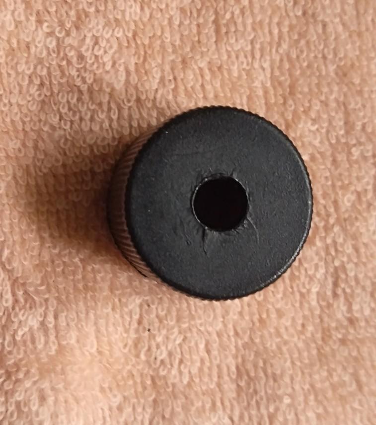
The better the pointing, the better would be the results. So I used a small cap (from a laser head) with a small hole at it's bottom. The user can point by viewing through the hole.
Obviously a laser could be used, but I did not had any spare. Also it won't help much in large distance calculations.
While fixing the cap remember to put it perpendicular to the frame. Otherwise it can lead to miscalculations.
User Menu


.jpg)
.jpg)
.jpg)


These are the user interface screens.
Result and Error
 vs. Measured height(cm).png)
 vs. Measured distance(cm).png)
I have done a variety of tests on the device. The above graphs show the results.
DISTANCE: Distance seems to be fairly accurate and multiple measurements of the same distance yielded results within 10-15 cm.
HEIGHT: Height measurement seemed to be more error prone. More of it is because of the pointing error. But if the pointing is done accurately the height measurement seems to be consistent even under repeated measurements.
The above graphs are for 15 measured values.
ERROR
Distance: Mean Squared Error (for measured values): 11.57 cm
Height: Mean Squared Error ( for measured values): 9.08 cm
Limitations and Further Considerations
Eventhough this device shows good accuracy for nearby and for objects lying on the same plane, there are some serious limitations.
This do not work on slanted objects: You can definitely find the object height (in a straight line) but it is not possible to find the object length.
Extremely calibration sensitive: Small errors in calibration can result in very large errors ( especially for large objects). This is because of the tan function that we use. For instance, tan 70 = 2.74 while tan 75 = 3.73, that is, a calibration error of 5 degrees can result in a scale difference of 1.37 and for larger distance this will result in large error.
Further Considerations:
Adding a laser pointer: The pointing accuracy will be improved very much by adding a laser pointer.
I know the build was not up to the mark but I enjoyed making it. Also the accuracy of measurement seems to be great :)
This was a very long instructables and thank you for reading until here.
Have a great day!!