AquaCharge Turbine - a Portable Water Turbine and Hand Crank Generator for Living Off-grid
by sam_havenhand in Circuits > Gadgets
497 Views, 4 Favorites, 0 Comments
AquaCharge Turbine - a Portable Water Turbine and Hand Crank Generator for Living Off-grid
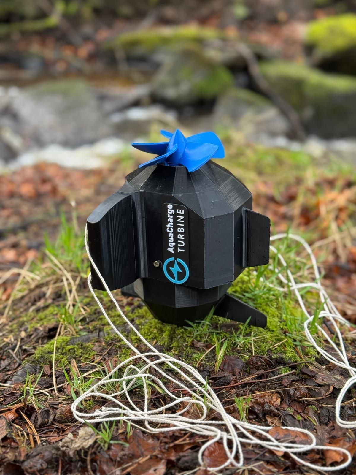
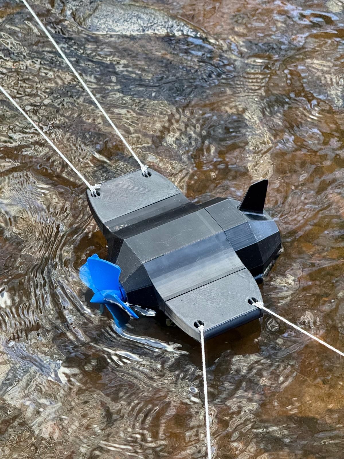
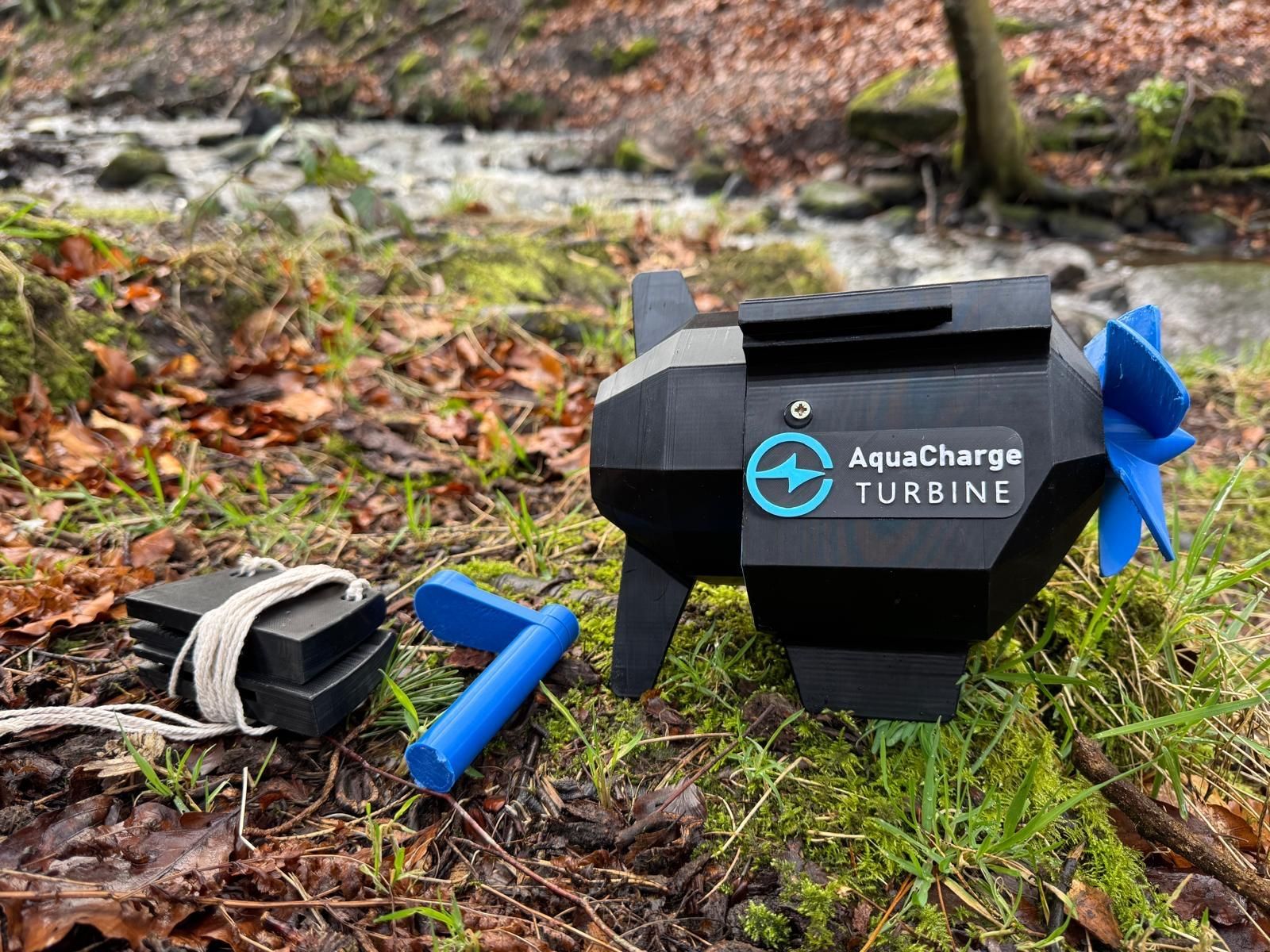
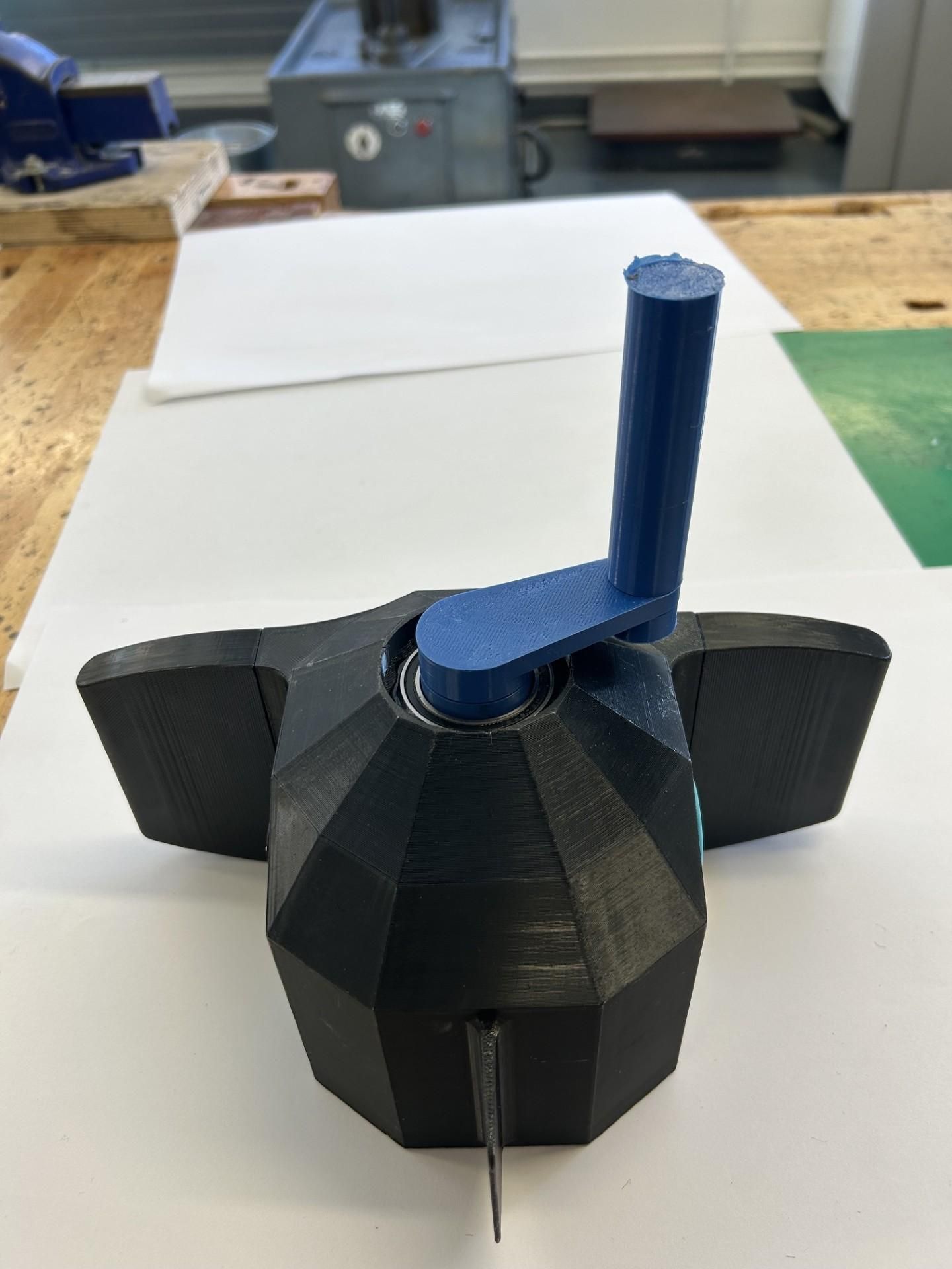
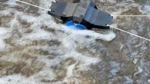
AquaCharge is a portable water turbine generator designed to convert the kinetic energy of flowing water in a stream or river into stored electrical charge. It is designed to run while a camper is asleep so they can charge their devices in the morning. (A full phone charge typically takes around 6 hours using the device)
The mechanism:
- Water directly spins the turbine blades, which spins a homemade alternator generating an AC voltage.
- Power output from the generator fluctuates greatly and isn't usable for charging, so the raw signal is fed through a bridge rectifier and buck-boost converter to create a stable 5V output
- The output can be hooked up to a power bank (as it could still be risky to directly charge devices)
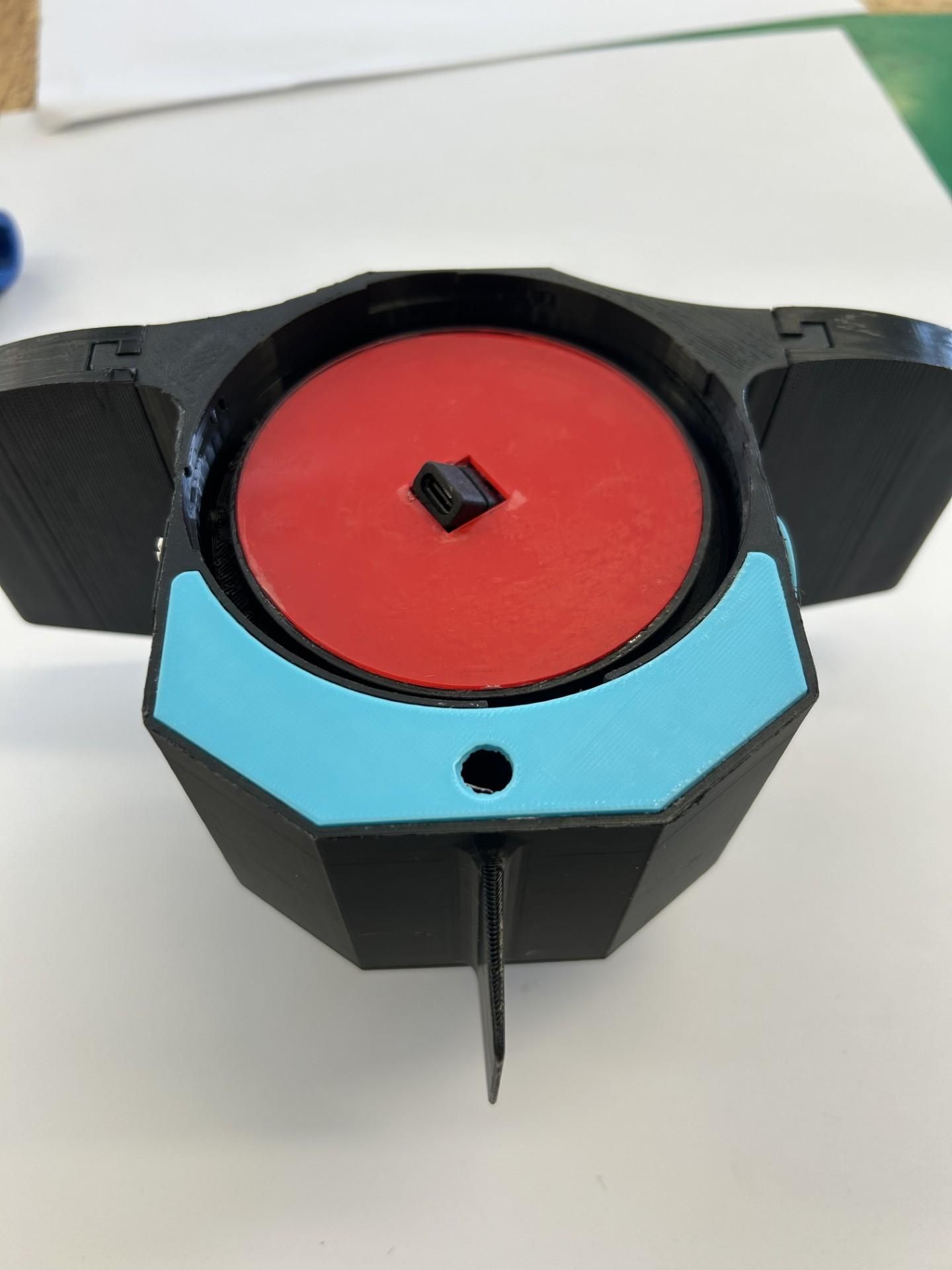
- The main body consists of two portions that connect with a waterproof twist lock mechanism so the power bank can be removed and used to charge devices seperately.
- The device uses a ballast tank that fills with water to lower the centre of mass without adding weight
Hand crank:
- The turbine blades can be removed and snapped into place on the front of the device
- This allows different modules to be attached instead the turbine, for example the hand crank attachment that can be used for more immediate power during emeregencies.
- Future modules can also be created like different turbine sizes for different river strengths.
Downsides to this:
- Securing the device in the river can take some time and may involve wet feet and multiple people as it is secured using pegs and guidelines (like a tent)
- The power generated isn't massive due to the strength of most rivers and size of the product, which is why 6 hours is the time to charge a mobile phone.
- The device weighs almost 1kg and while the wings can be detached campers may find it still uses significant space in rucksacks.
Supplies
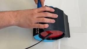
- Approx 210g of PLA and 560g of PETG 3D printing filament
- 24 neodymium magnets (10x20x3mm)
- 1 or 2 large coils of 0.2mm enamelled copper wire (depends on how tight you wind coils and desired power output)
- 4 diodes
- Buck-boost converter (usually sold in bulk unfortunately)
- Small stripboard or breadboard
- USB-C female connector
- 5 8x22mm ball bearings
- 30x42mm waterproof ball bearing
- 30x42mm shaft seal
- 105mm silicone o ring
- Small power bank (dimensions around or under 53x74mm)
3D Printing Alternator Components
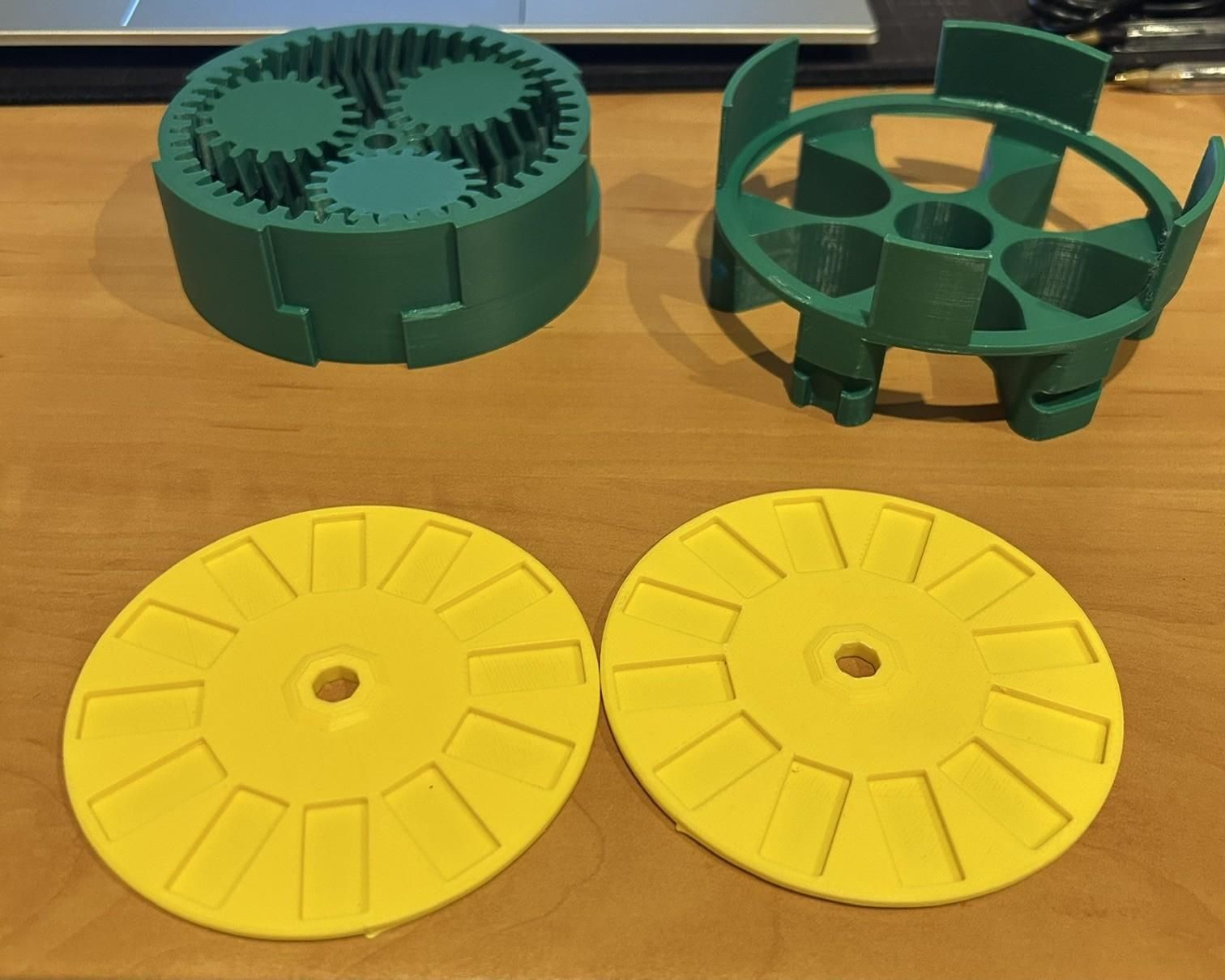
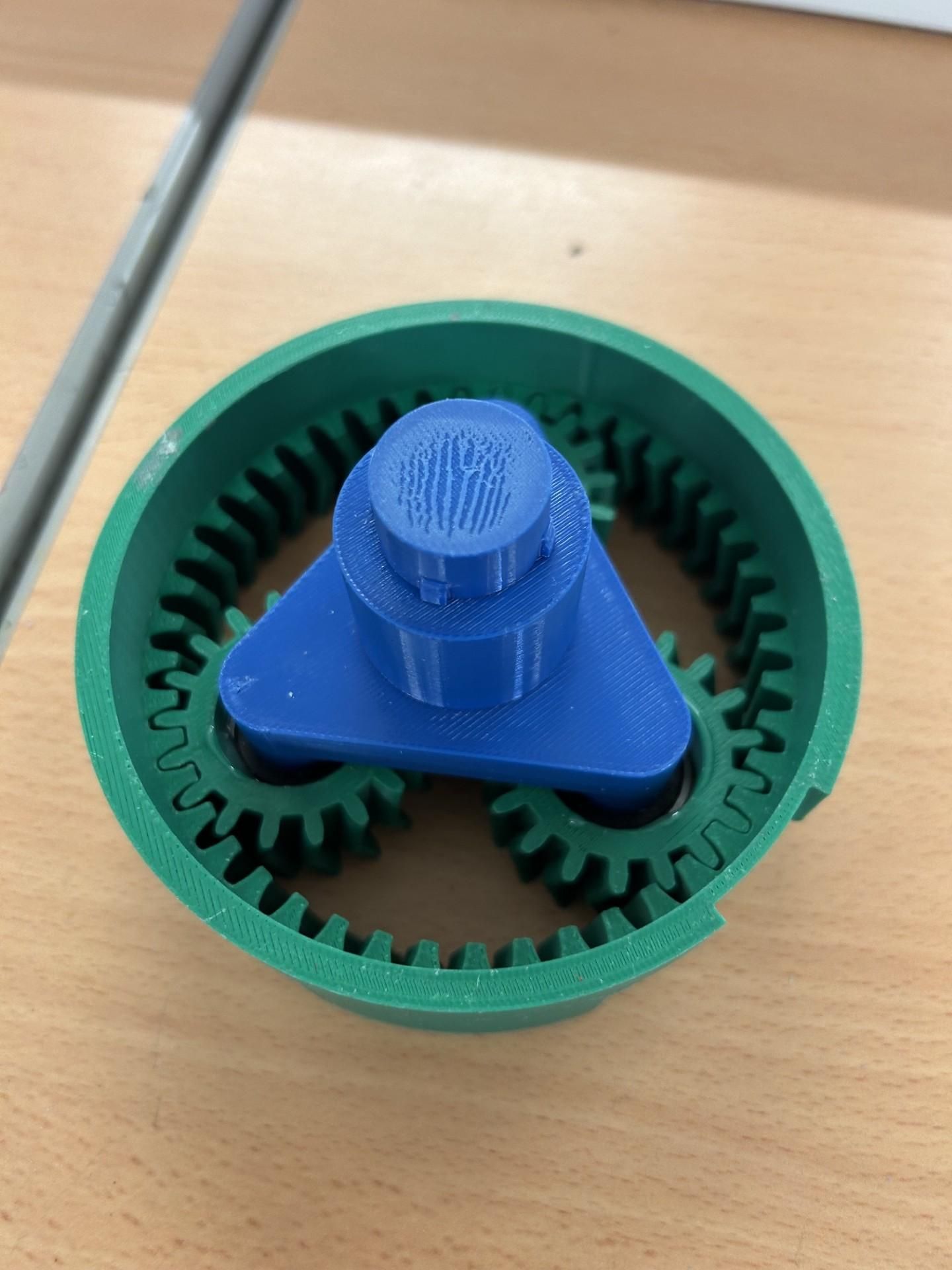
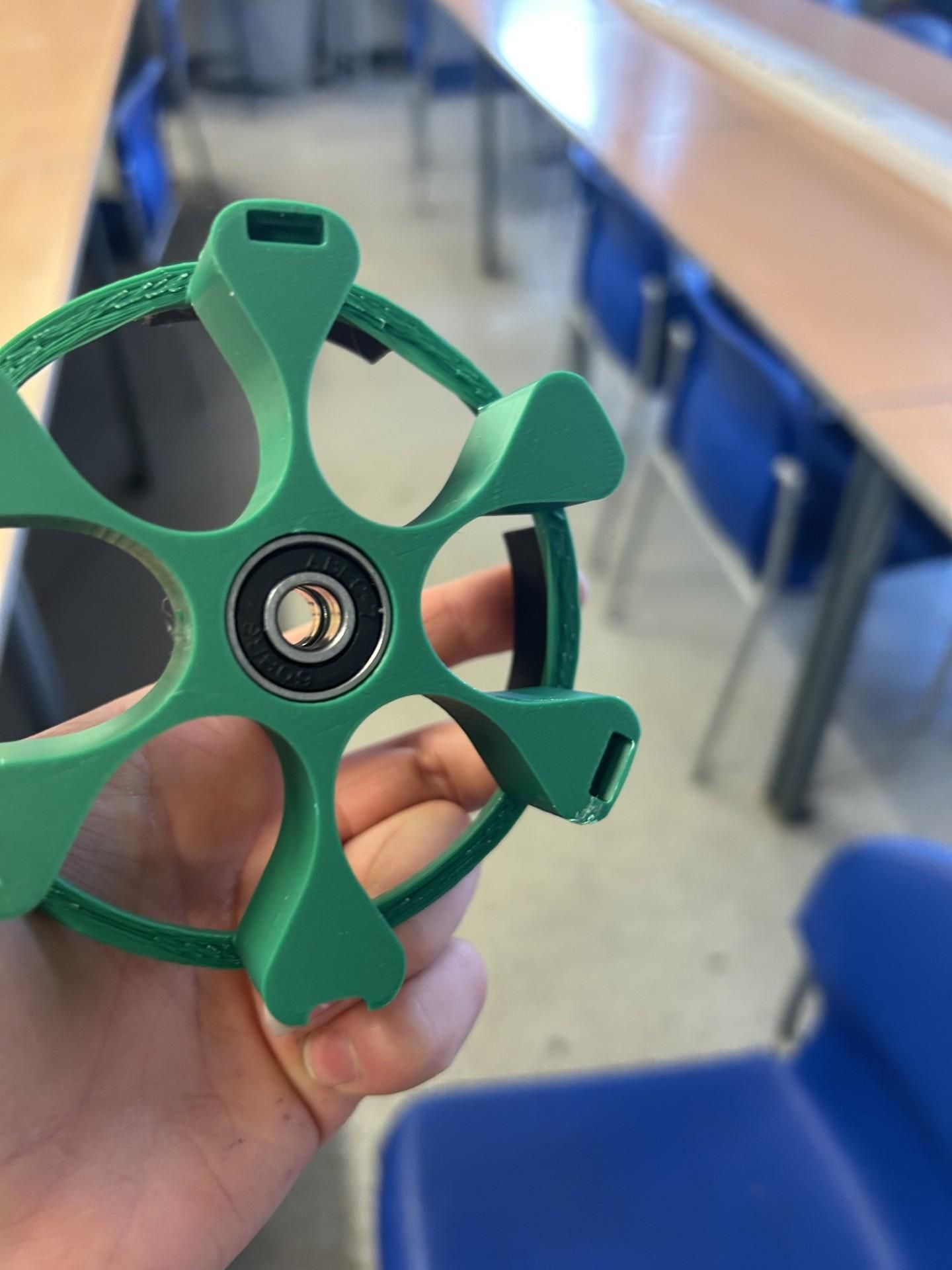
First we need to 3D print all the components used for the alternator. I recommend using PETG for as many parts as possible (especially rotating parts like the shaft, gearset and rotors), but PLA can work too.
The planetary gearset needs to be 3D printed with the gears flush with the print bed as it is a print in place herringbone gearset (gears cannot fall out once printed)
Supports are needed for the stator and for the planet carrier.
Creating a Single Phase Alternator
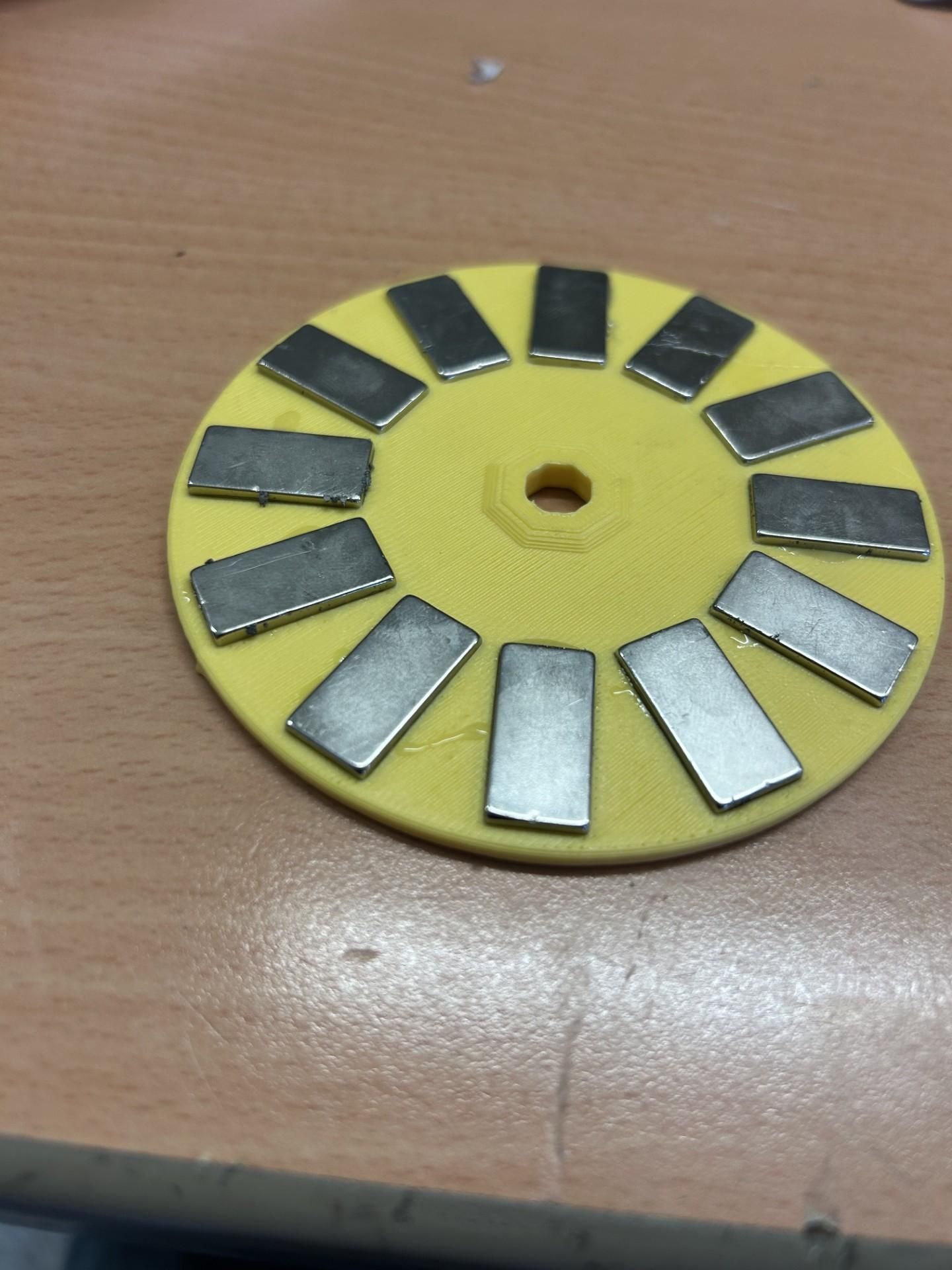
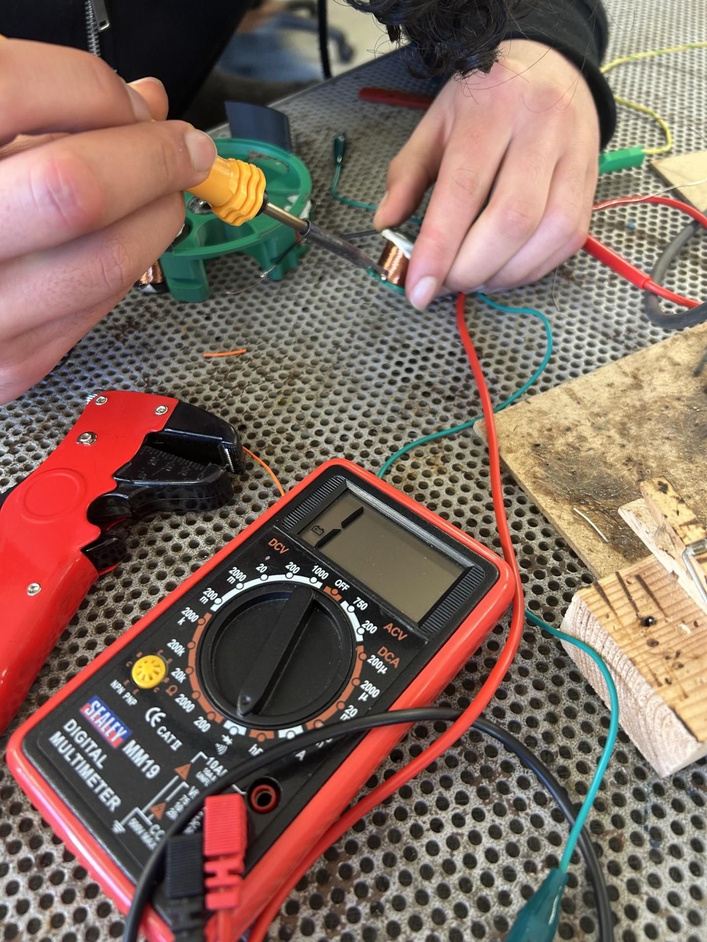
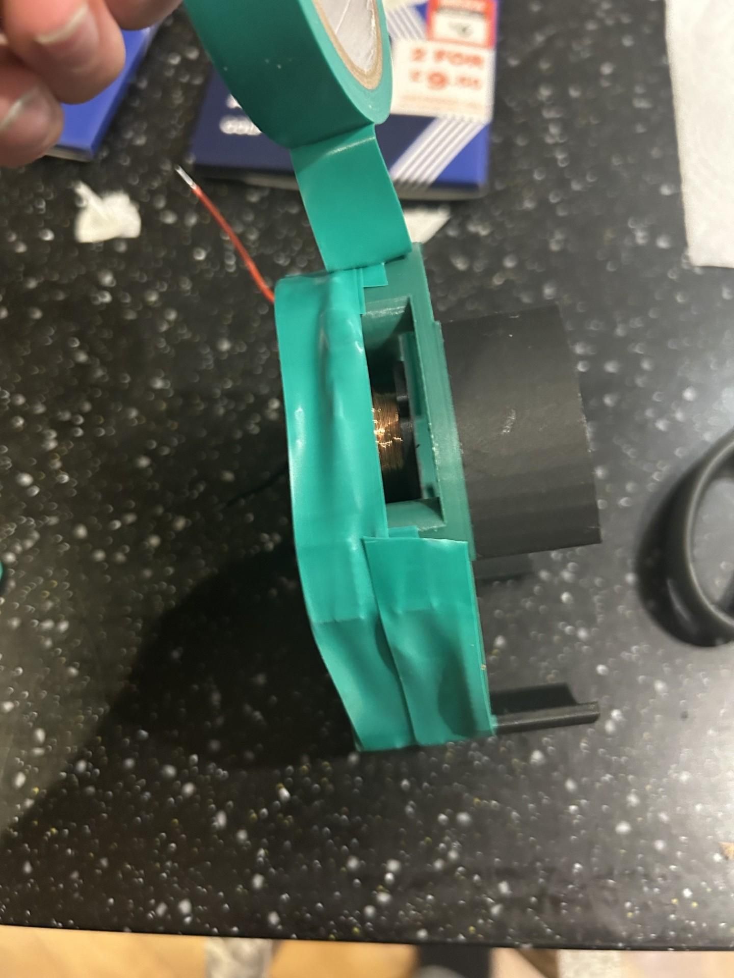
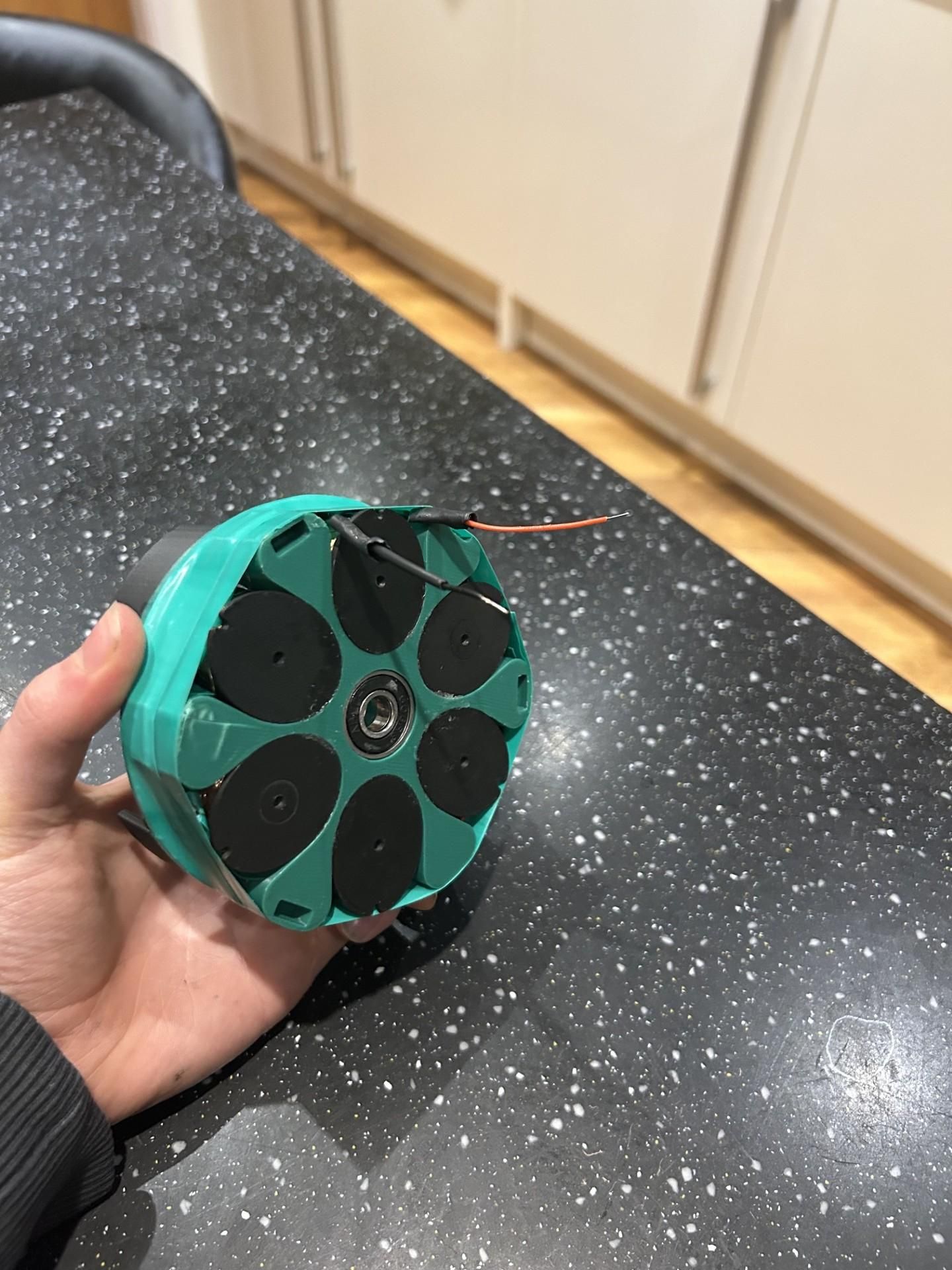
First we need to use glue the magnets into the rotors using epoxy / hotglue etc. Ensure each magnet is opposing polarity to its adjacent magnets (pattern N S N S...)) Use marker pen on magnets or use a seperate magnet and hover it over each to feel the push or pull to ensure they are in correctly. (The polarity of the magnets is on the two opposite faces not the ends)
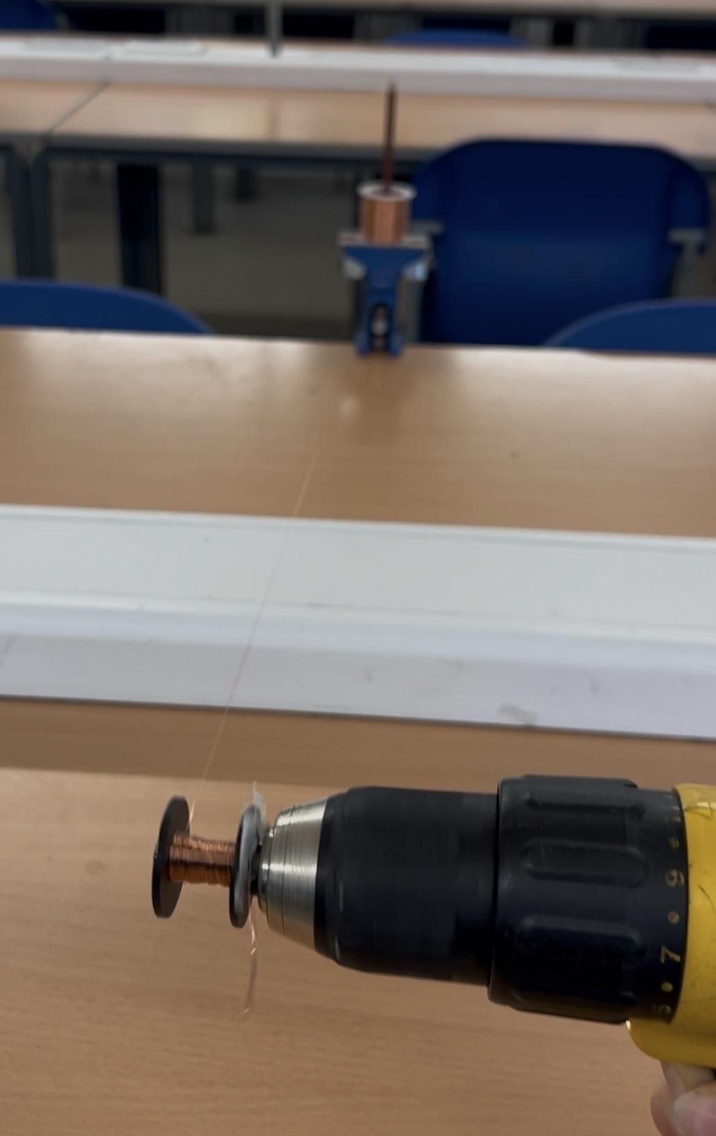
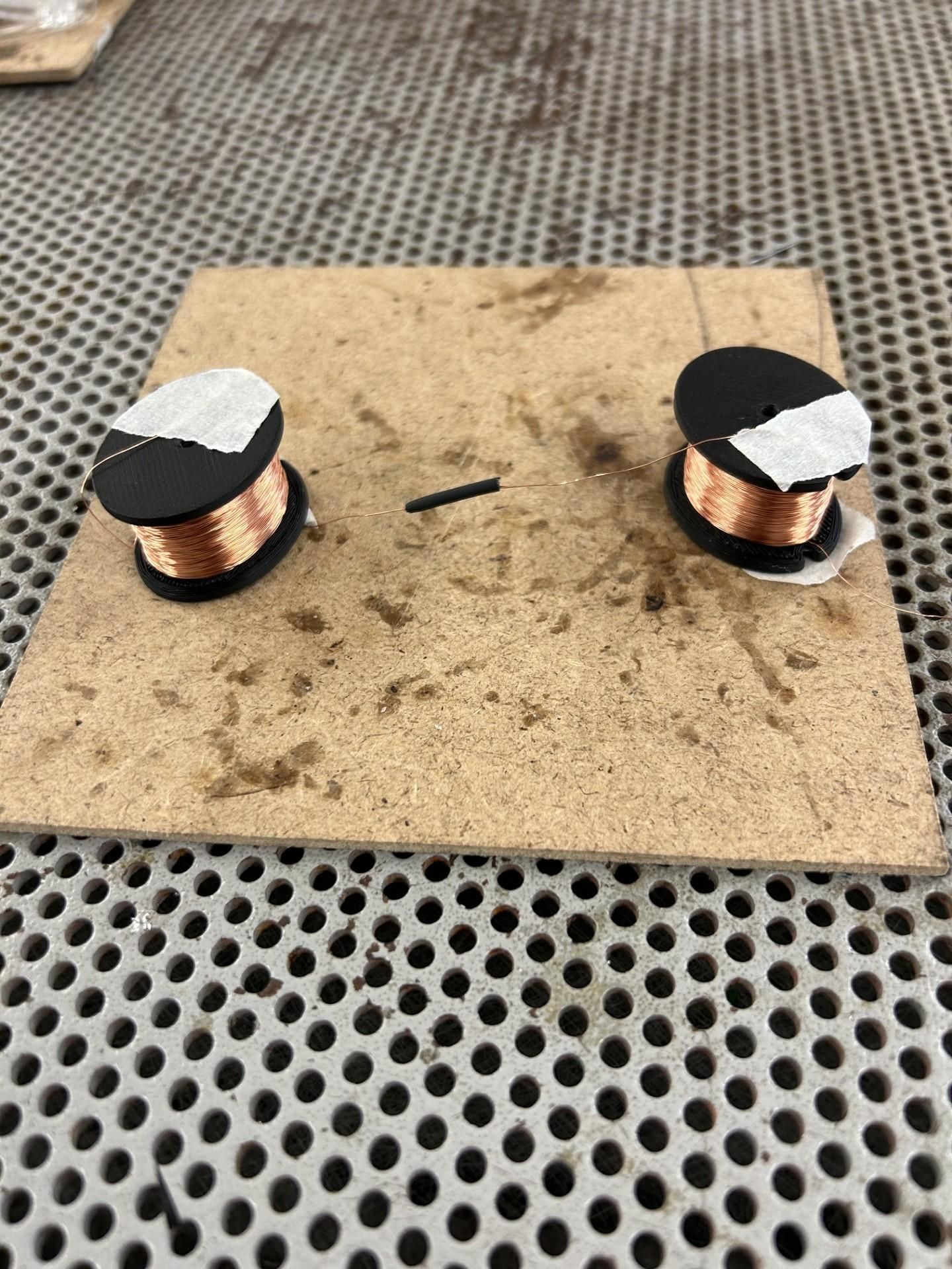
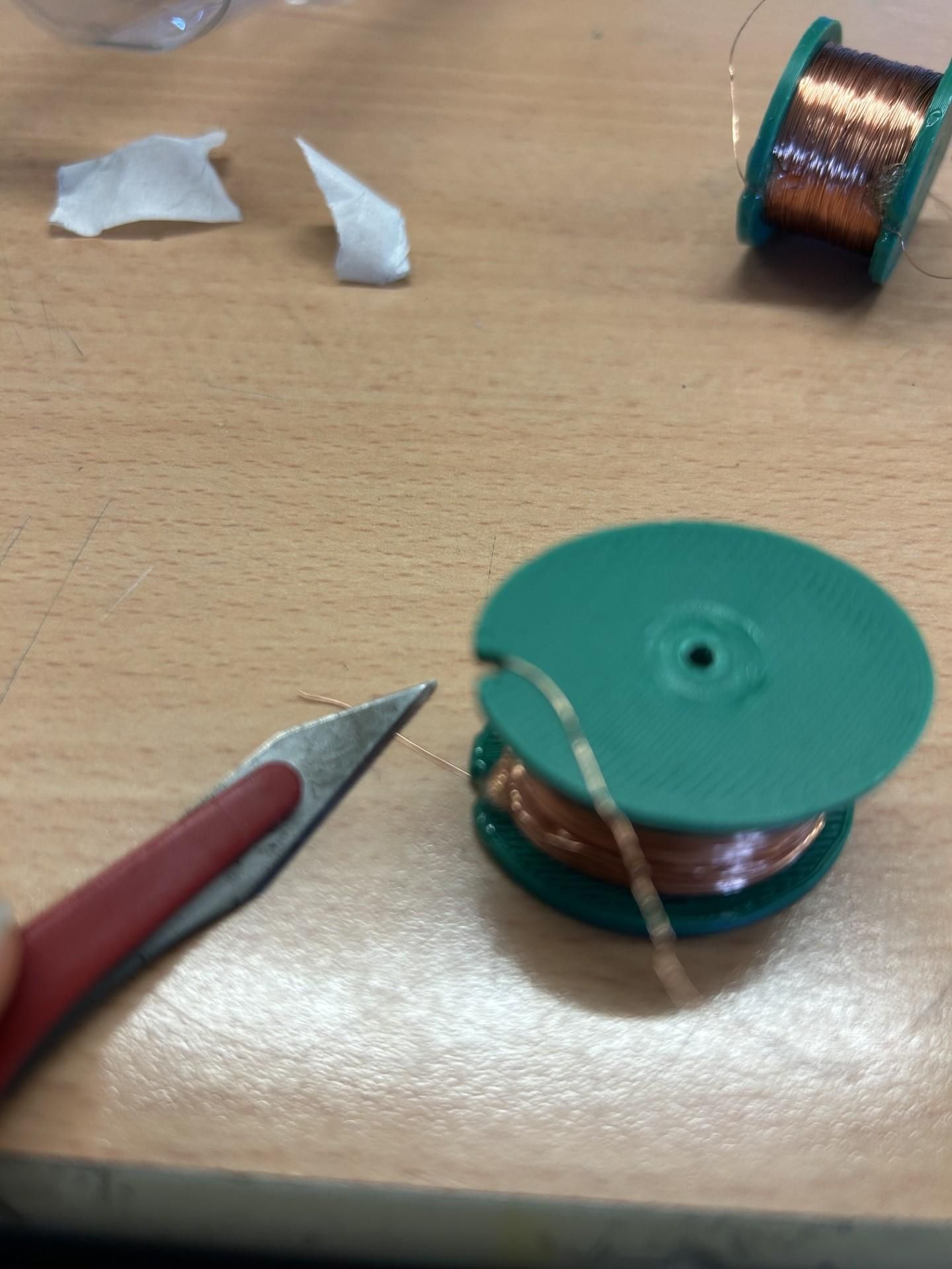
Next we wind the copper coils. Secure one end of wire onto the side of the coil so we can solder ends together later (use tape for now and glue later because if the wire snaps the end can get buried in the glue making the coil unusable which I found out the hard way) You can wind by hand but I recommend using a hand-drill, by putting a bolt or screw in the centre hole of the coil and clamping the drill end around the bolt. Try to wind each coil with around the same thickness of turns. Tape the other end of the wire to the other side of the coil to avoid unwravelling, then cut the wire.
As we are using enamelled copper wire to solder ends together we need to strip the enamel off the ends, this can be done with a scalpel or soldering iron, try not to snap the ends off while doing this. Also, at this stage use a multimeter to ensure current passes through each coil from end to end as if there is any breaks in the wire this coil cannot be used.
Next we need to solder 3 coils together in series (This means only two junctions need soldering). Use heat shrink on each junction to avoid shorts. Create two sets of these 3 coils as these will be in parallel together in the stator later. (Use a multimeter to check current flows through the connections once again)
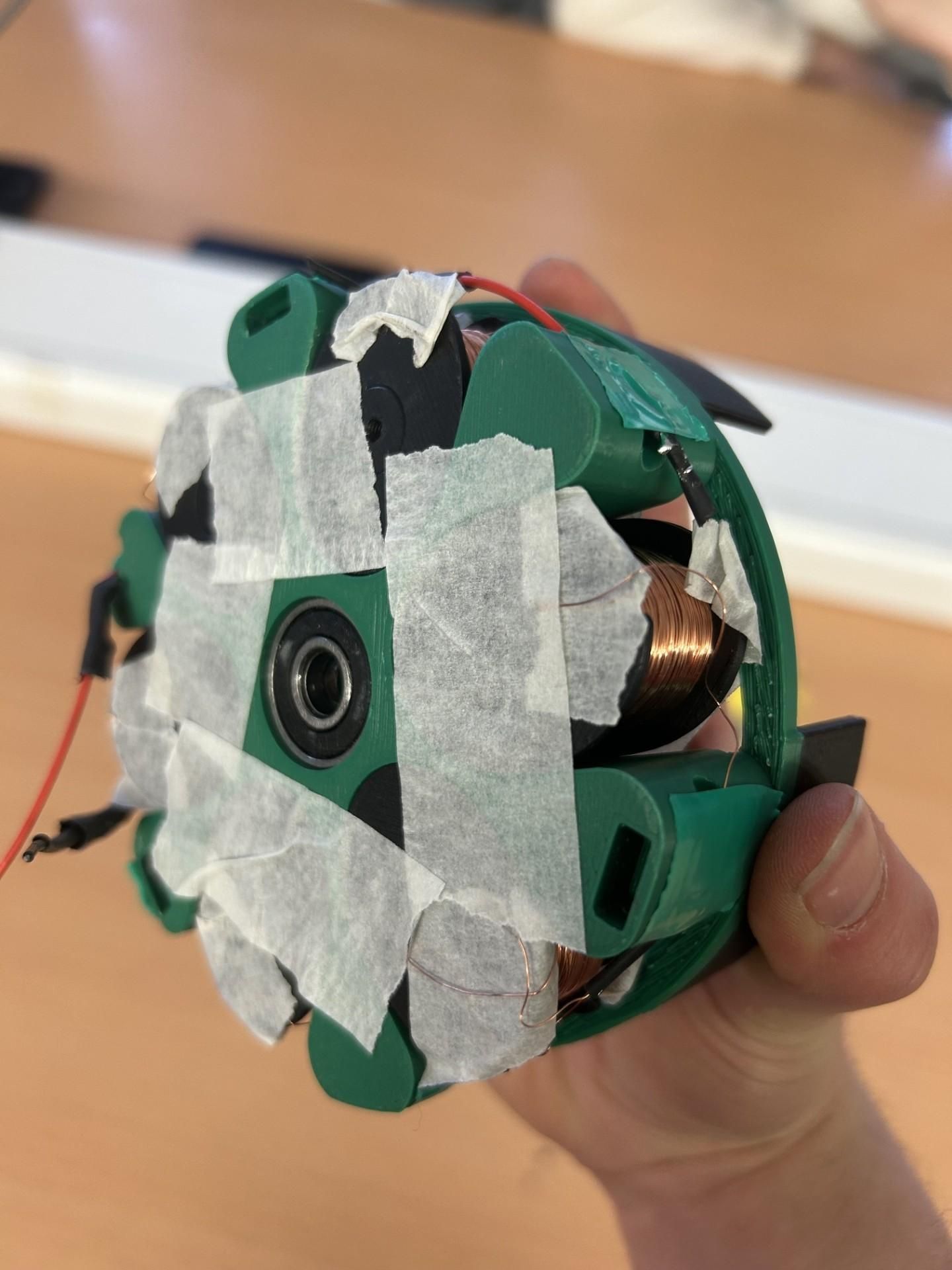
Now secure the coils in the stator using tape, and using seperate wires solder the sets together in parallel, with an input and an output wire (picture a path branching into two and then the two conjoining at the end again). Test with a multimeter to make sure current flows.
At this point if everything works then glue everything that tape is securing right now. I'd also recomend wrapping electrical tape around the outside so there is no risk of snapping any wires if the alternator is dropped
Now assemble and glue to rest of the components in the configuration shown in the diagram below, using ball bearings in neccesary spaces (should be obvious where they are needed). The two rotors should be opposite each other with a north facing magnet looking toward a south facing magnet (otherwise they repel and reduce the power output dramatically)
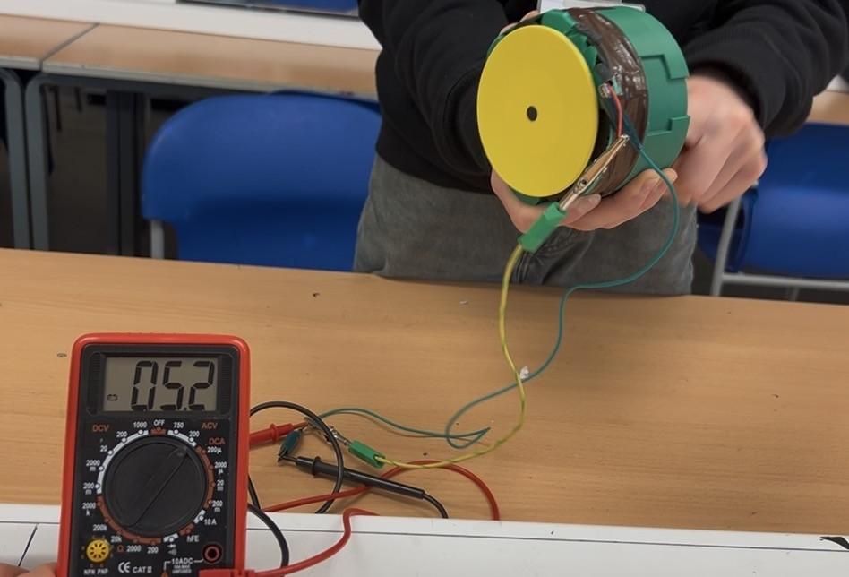
Test that everything works, use a multimeter to measure the ac output when the planet carrier is spun (should get to around 5V AC. If this works then well done, the hardest part has been completed.
Electronics
We now have a generator, but we cannot use the output for charging purposes yet because of a couple reasons:
- We have an alternating output (the charge of the output wires is constantly switching between positive and negative), so it needs converting to direct current to be used for charging.
- The net power output also fluctuates based on rotation speed and does not remain the constant 5V neccesary for charging devices
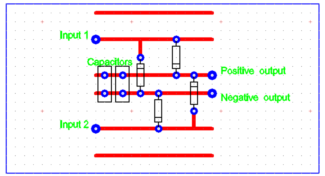
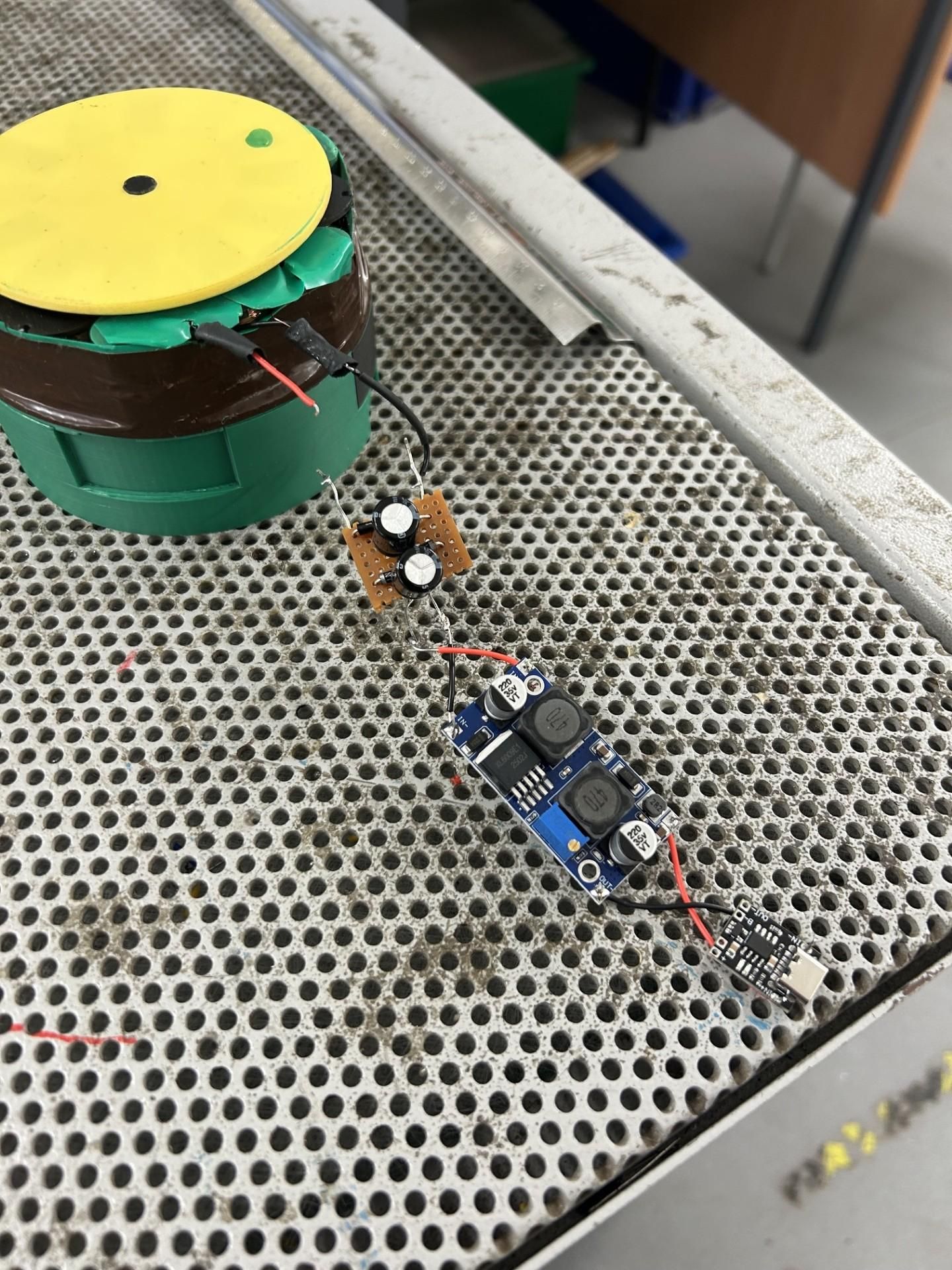
The solution to this is a circuitboard incorporating a bridge rectifier (four diodes that direct current so we can have a positive and negatively charged wires), with a couple 470uF capacitors that help to smooth the output voltage as a bridge recitified output is very bumpy. Then, to ensure a constant 5V output we connect up a buck-boost converter (this is an electrical component that will "boost" voltage to 5V when the output is too low and lower voltage to 5V if the output is too high)
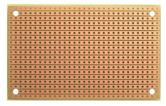
For the bridge rectifier circuit, use a stripboard (circuitboard that behaves like a breadboard where lines of copper can connect components together) and follow the diagram given above for soldering diodes and capacitors (remember diodes are directional so follow directions shown). Each red line represents one of the tracks of the stripboard.
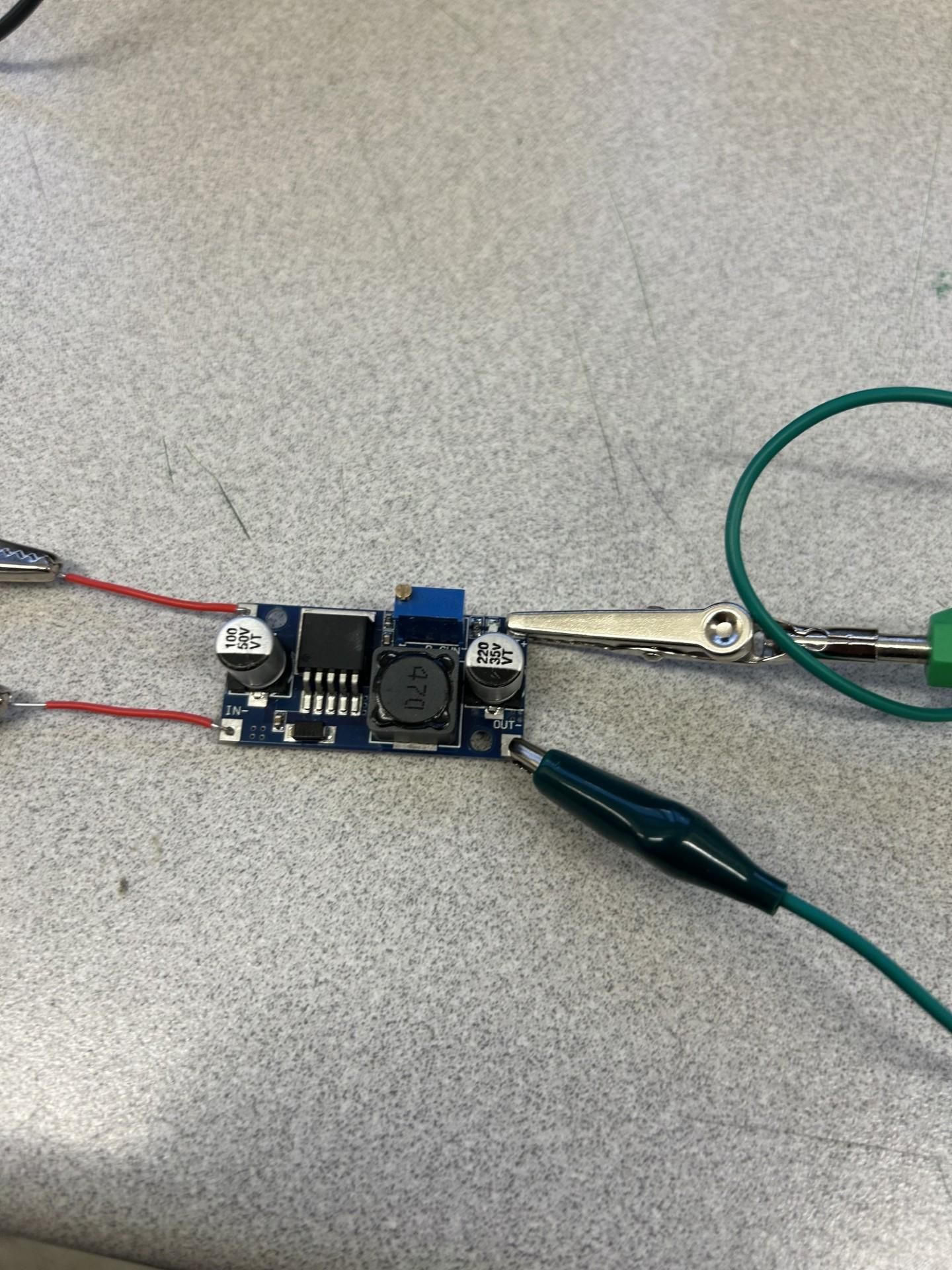
After this, tune the potentiometer on the buck boost converter (use a screwdriver) so it outputs 5V by connecting the inputs to a d.c power supply and using a multimeter to measure output voltage. Then use flying wires to solder the positive and negative outputs of the bridge rectifier cirucit to their respective connections on the buck boost converter
To add the usb-c connector, use a knife or scalpel to shorten the cable that is attached to the connector to as short as possible where the positive and negative copper wires inside are still able to be soldered with. Then solder these copper wires to the buck boost converter output. Now (in theory), you can charge your phone with the alternator, however to avoid risk of these components not working which could be hazardous to your phone, I still recommend charging a seperate power bank first then charging devices from that power bank
Electronics Compartment
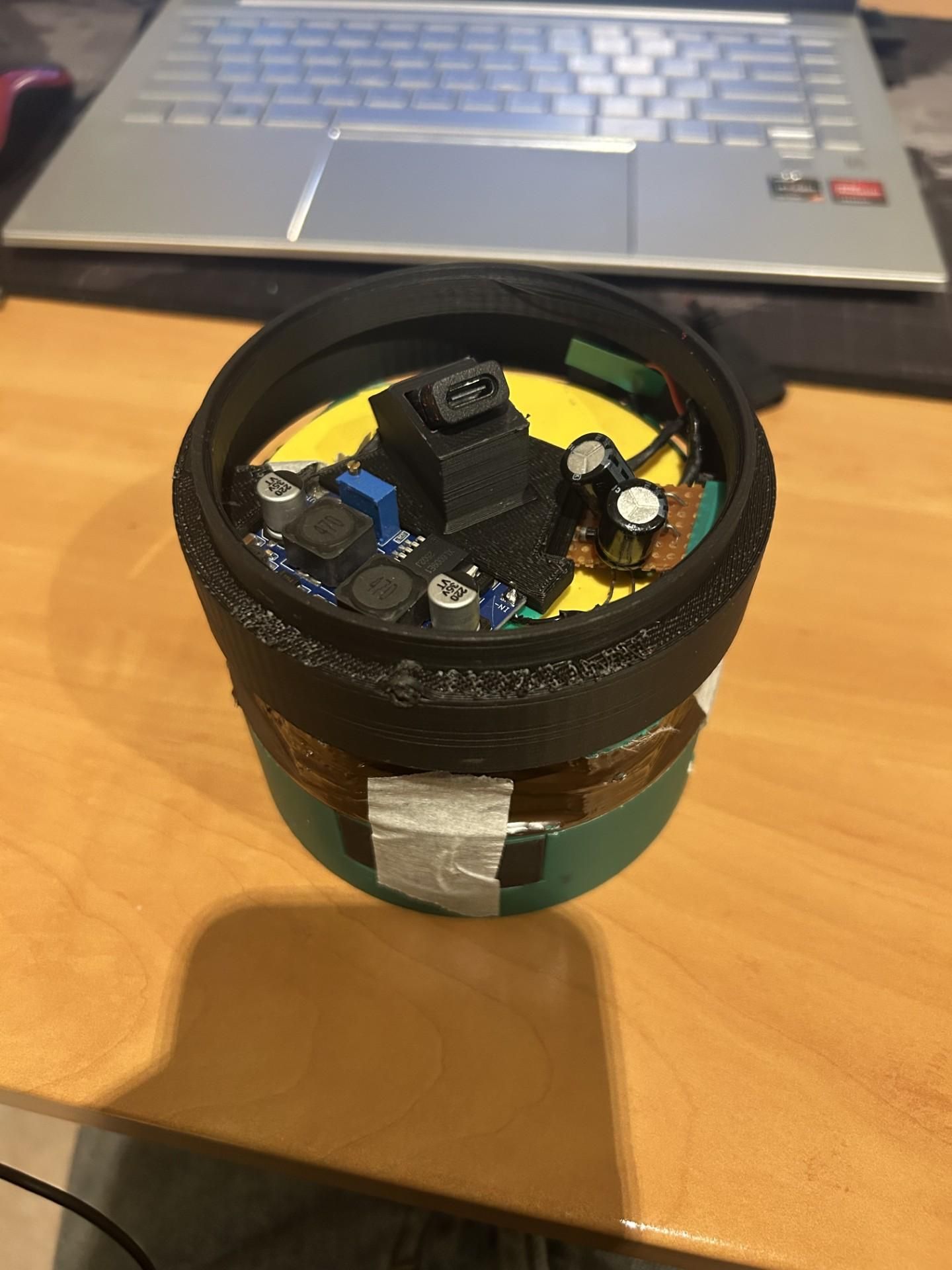
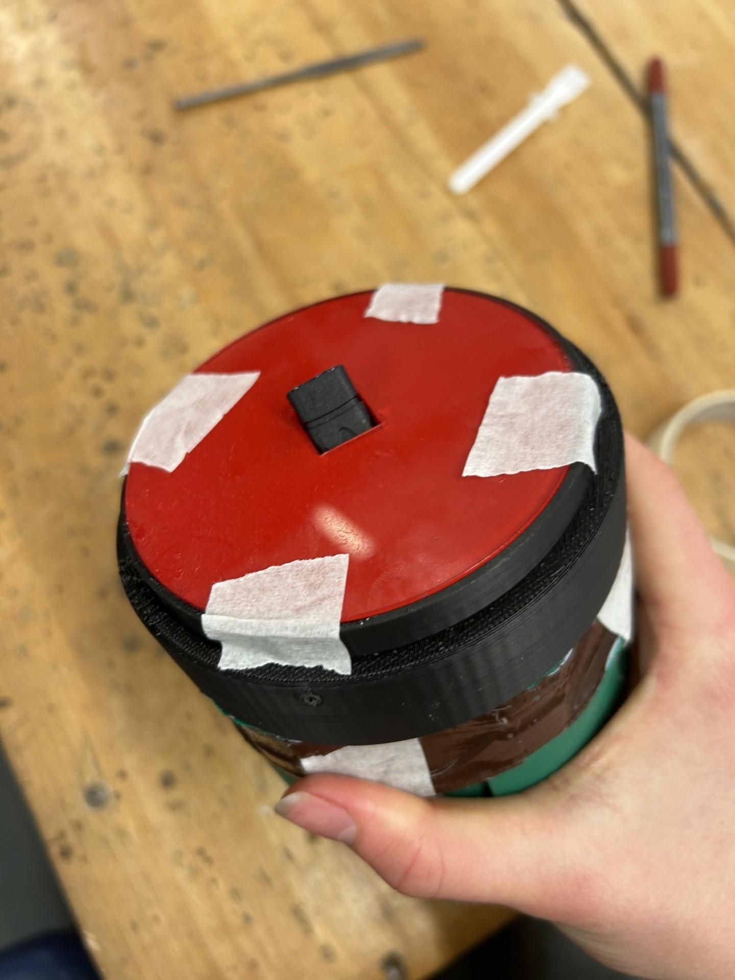
The attached 3D model is customised to house the electronics in the last step, where each component (stripboard, buck-boost converter, USB-C cable) fits seperately with wires connecting. Be prepared to use tape or glue to secure them and to reduce flying wires)
You can choose to either 3D print or laser cut the overlaying panel that covers the electronics and glue that in place
The electronics compartment can then snap fit directly onto the alternator, completing the inside of the Aqua Charge turbine.
3D Print Body
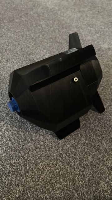
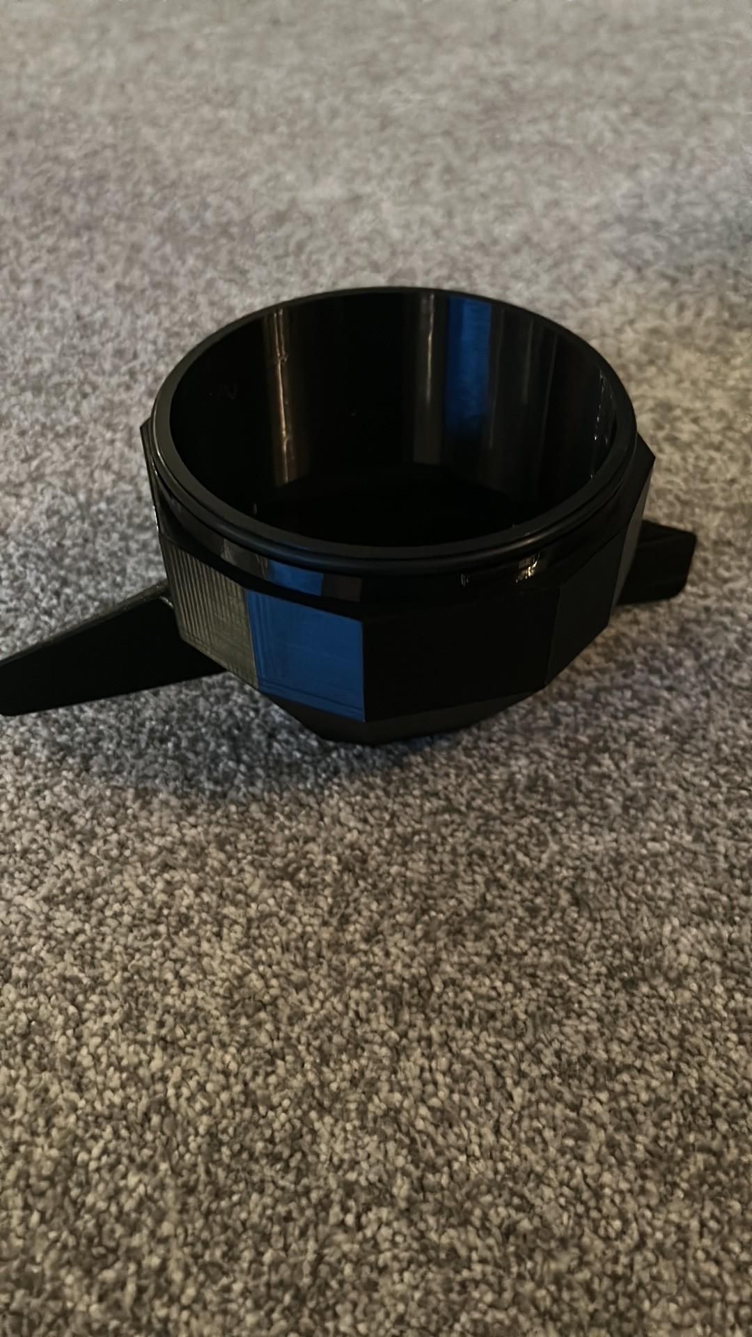
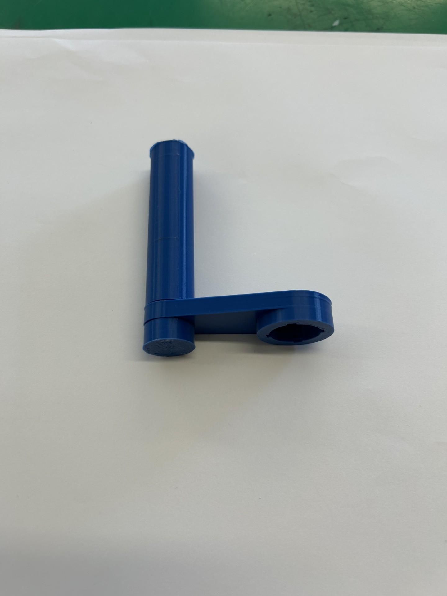
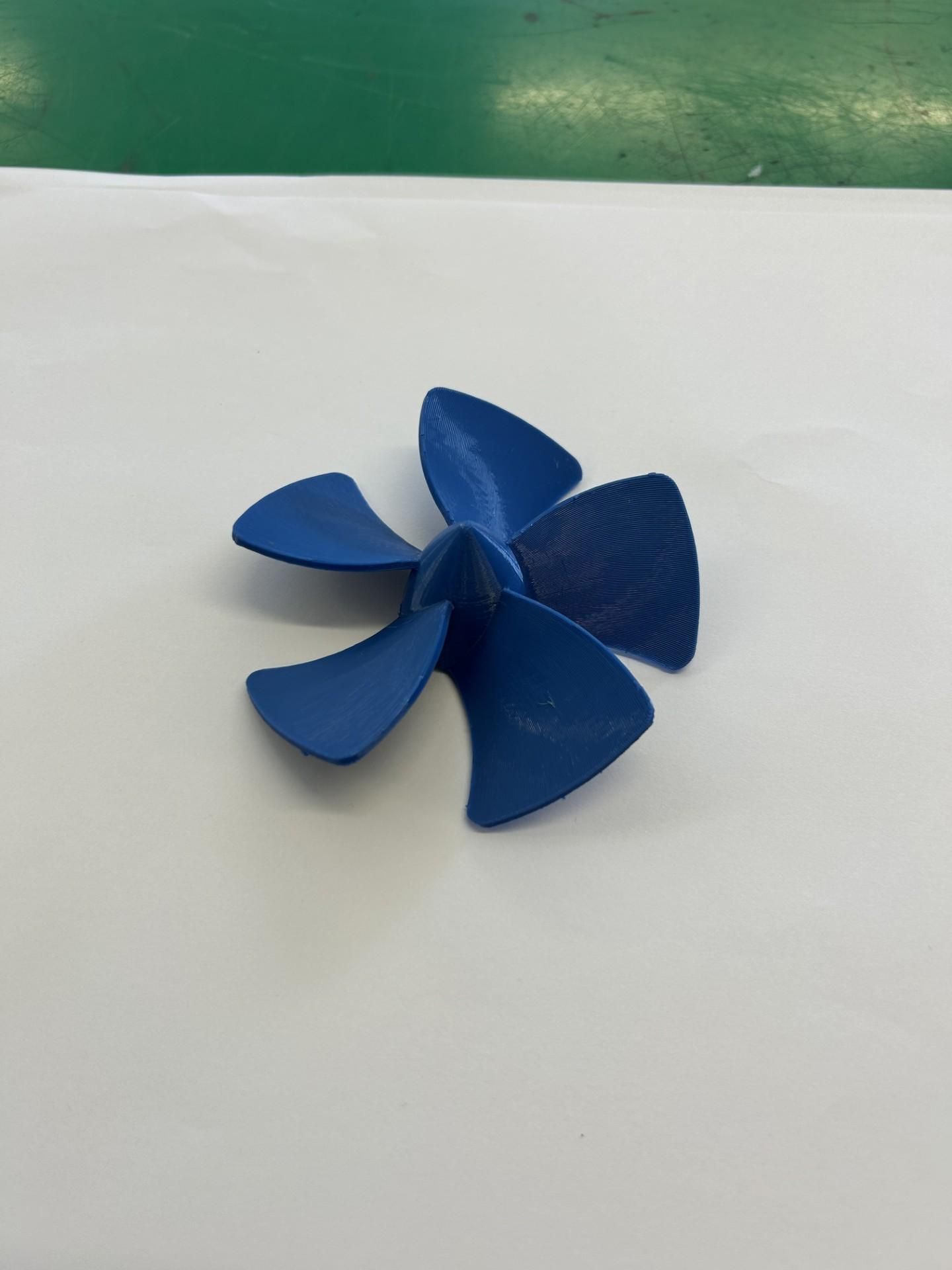
Now we 3D print the rest of the parts. All these parts should be printed in PETG with most needing supports. The main shell should be printed with the end of the hollow section on the bottom of the build plate for better print quality (though it will increase the amount of support neccesary)
Check the two shells can connect together using the twist locking mechanism built into the components (we will waterproof the connection next step)
Ensure the ballast tank wall fits into the end of the ballast tank on the main shell.
Check the two wings slide onto the main shell and aren't too loose.
Finally, check the hand crank can be assembled (relies on the 3D printed threads being printed correctly) and both the turbine and hand crank can snap fit onto the end of the alternator.
Finishing
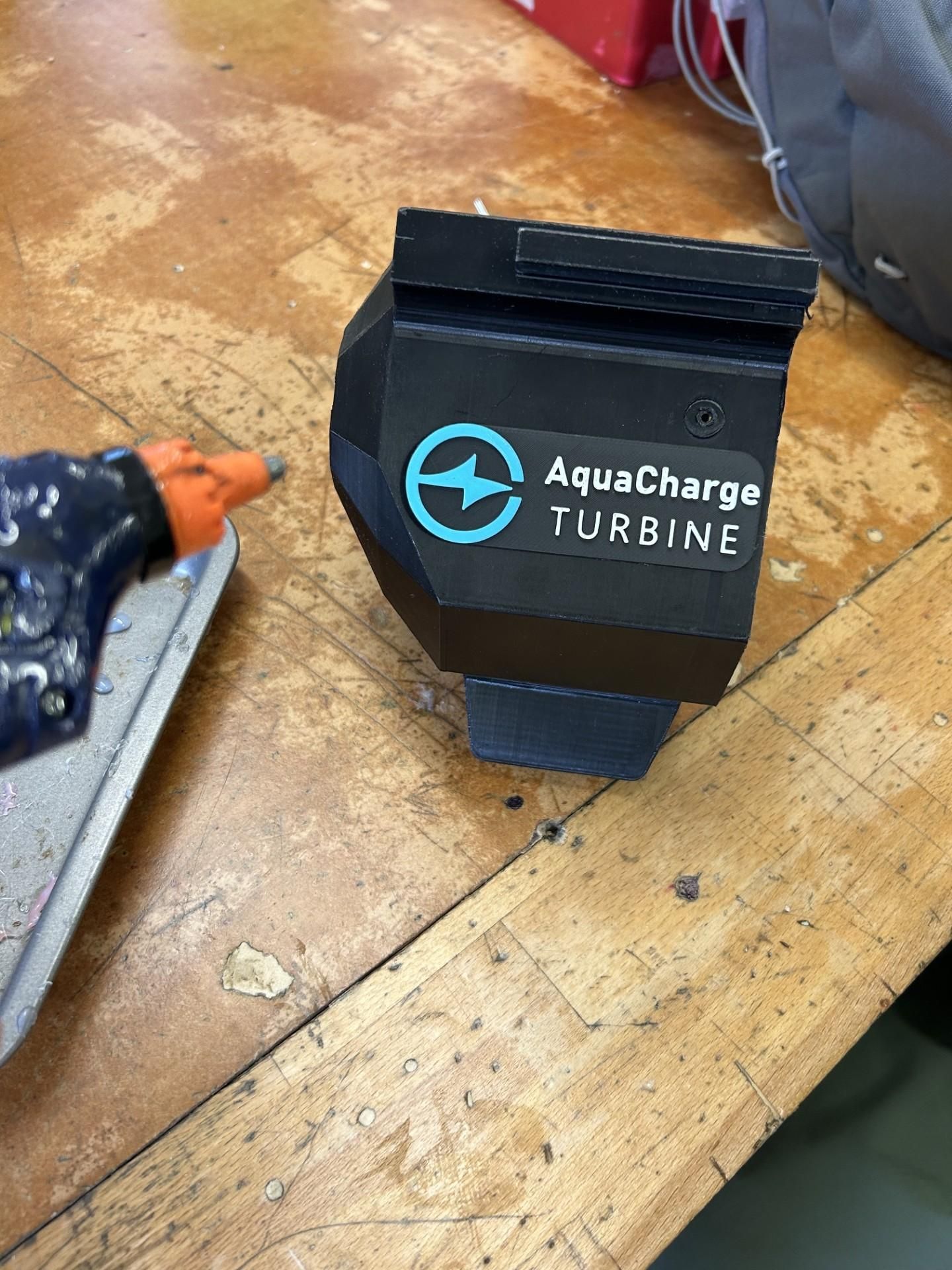
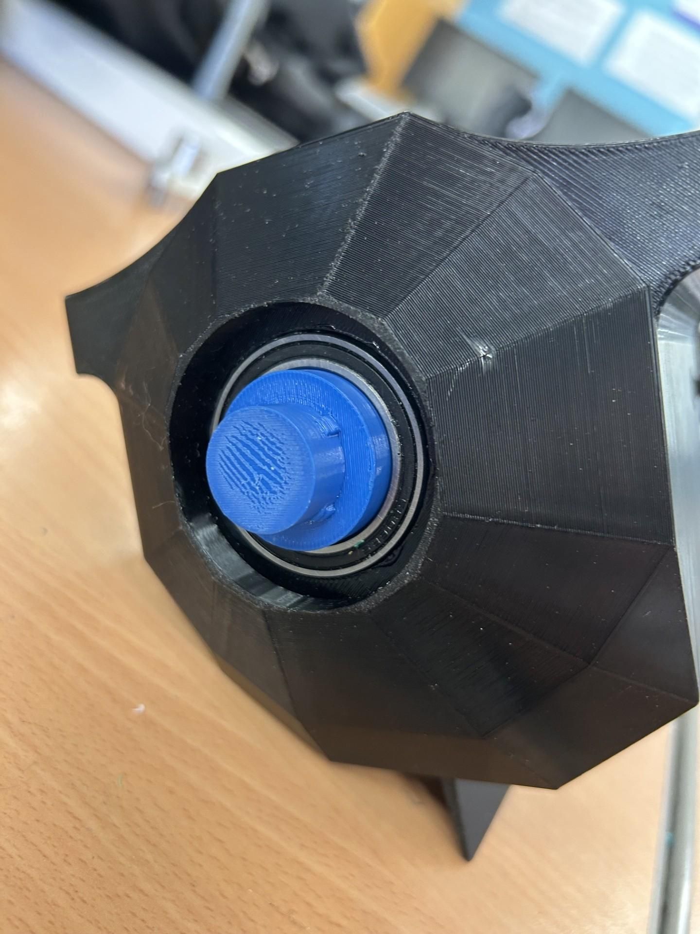
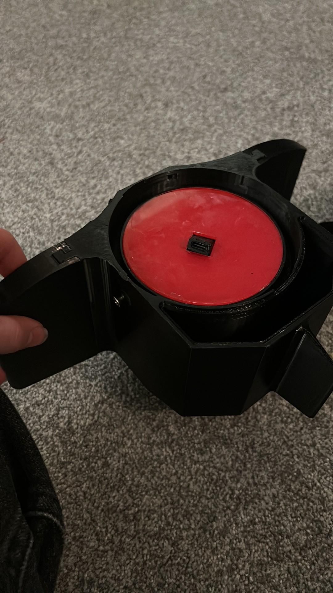
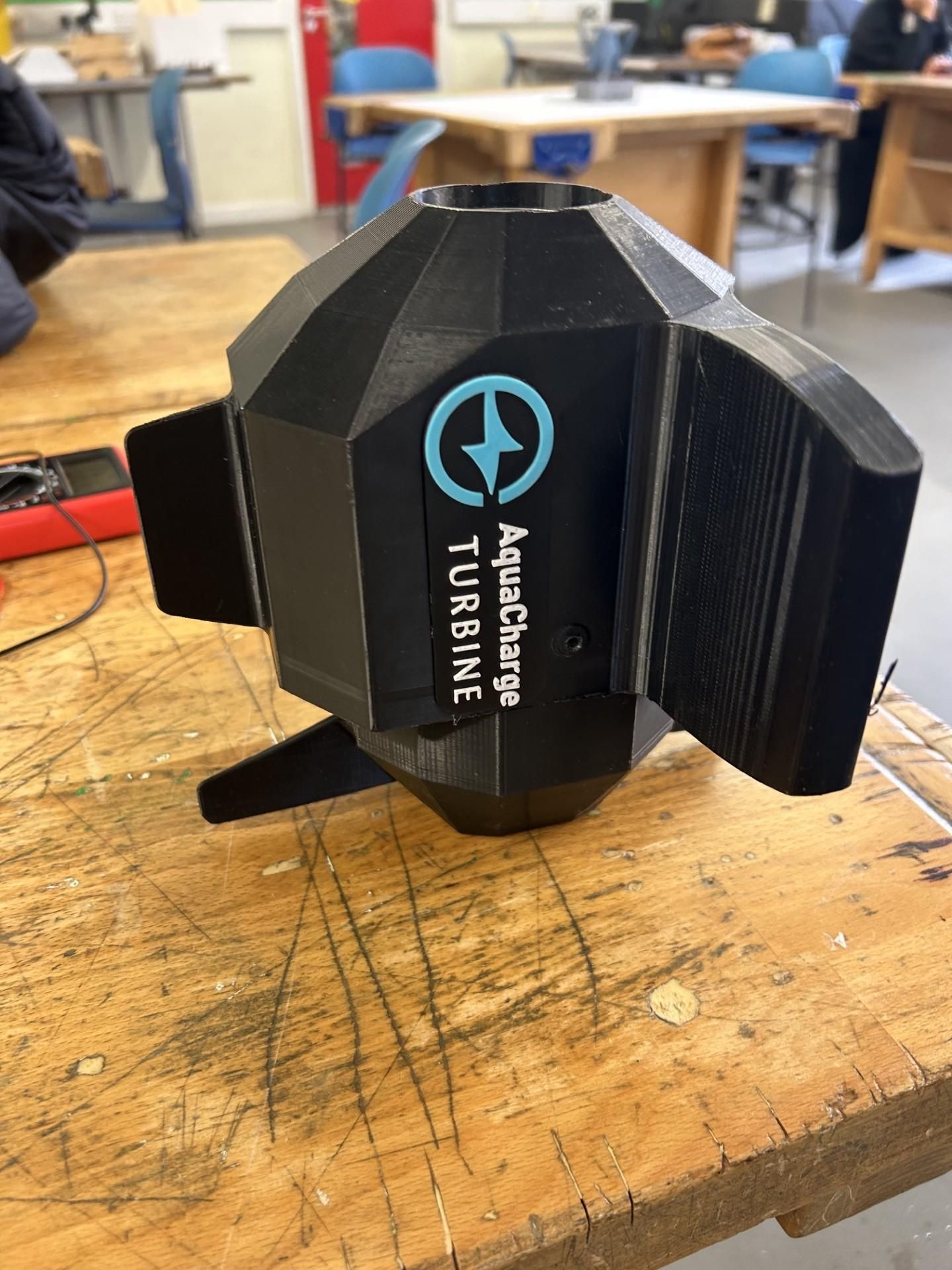
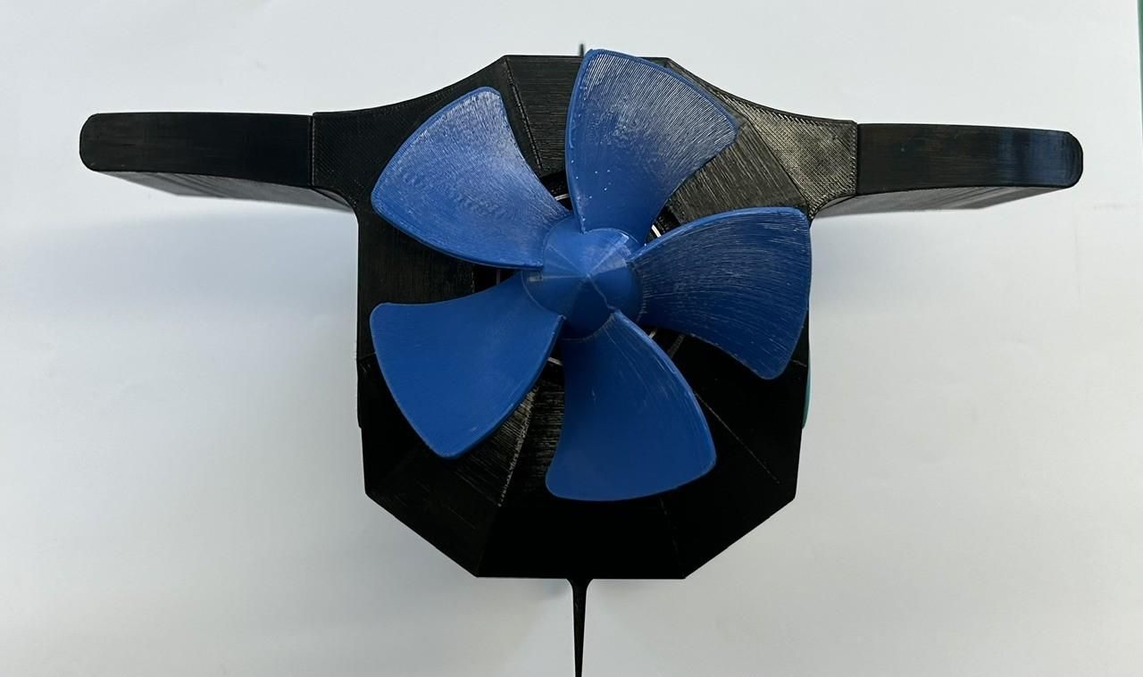
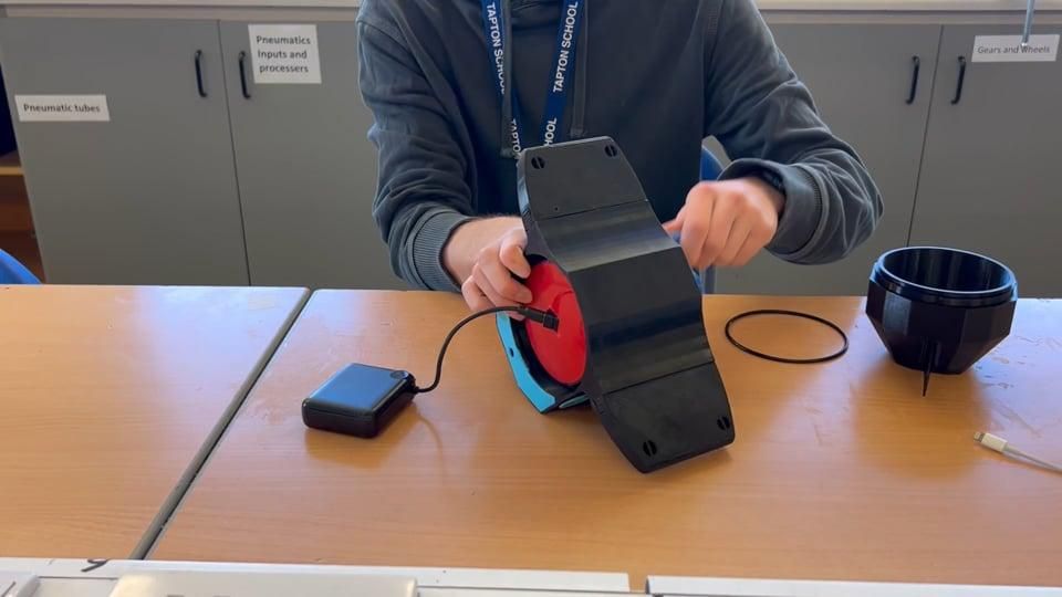
For this final step we assemble the entire device.
Use epoxy to glue the 30mm bearing and ensure the alternator can fit into it properly.
You can choose to 3D print the logo either in three colours if your 3D printer has the capability or in single and paint it afterwards.
When the alternator (with electronic compartment attached) is slotted into the body, you can use screws on the outside to secure it in place (secure screws on the two markers to avoid creating holes for water to leak into)