Arduino Anti-Snooze Alarm System
by serene448 in Circuits > Arduino
79 Views, 0 Favorites, 0 Comments
Arduino Anti-Snooze Alarm System

Idea
For my Design Thinking course at Yonsei University, our task for the semester was to create an original Arduino prototype that aims to address a specific problem. After some thought, I chose a problem directly relevant to my personal experiences: the never-ending cycle of hitting snooze and falling back asleep in the morning. I designed my system specifically for people like me, who set multiple alarms every day but still fail to wake up. The main goal was to gamify the process of waking up by adding a more dynamic, interactive element beyond just smashing the snooze button and falling asleep again.
Final Result
My final prototype is a two-step anti-snooze alarm system. The first alarm presents the user with a memory game using a joystick and LEDs. If they input the pattern successfully, then they have to physically get out of bed and trigger a PIR motion sensor to deactivate the second alarm, which discourages falling back asleep after hearing your first alarm. If they fail to activate the motion sensor within 50 seconds, the system restarts from alarm 1.
My first alarm system proposal only involved a motion detector, buzzer, and Arduino board. The prototype I created for the midterm evaluation utilized a joystick, LEDs, and a buzzer. So, my final prototype combines all my ideas thus far, with the addition of an OLED screen and PIR motion sensor module.
Supplies
See attached PDF.
Downloads
System Explanation
Before we get into it, let's understand how the system actually works.
- Alarm 1 rings, with accompanying buzzer sound and OLED interface: '9 AM, ALARM 1, Press Joystick'.
- User follows instructions on screen and presses down on joystick.
- OLED screen says 'Watch Pattern' as random 4-LED pattern is generated, then OLED says 'Repeat Pattern'.
- User enters pattern and presses joystick again to confirm.
- If correct, green LED lights up and alarm 2 stage is initiated ('Alarm 1 Deactivated' + checkmark). If incorrect, red LED lights up and 'Try Again' + X mark are displayed on OLED. User is sent back to step 1.
- In alarm 2 stage, 50 second countdown begins, with instructions to move to sensor on OLED display.
- If user successfully gets out of bed and passes by PIR motion sensor, alarm 2 will be deactivated and OLED says 'Motion Detected!', followed by 3-second countdown, then good morning message.
- If user falls back asleep after alarm 1, countdown runs out and OLED says 'Alarm 2 Not Deactivated', effectively restarting system from step 1.
Arduino IDE Code
Make sure to install Arduino IDE on your computer, as well as the Adafruit_GFX and Adafruit SSD1306 libraries from Arduino IDE (Tools > Manage Libraries), and use the ssd1306_128x64_i2c Adafruit library if you're using the same exact OLED model as I did.
There are two codes for this project. The first code is the final code necessary for the whole system to run as intended, and the second code is a basic test for only the PIR motion sensor to ensure that no residual infrared radiation is detected before testing the project from start to finish.
Disclaimer: All code was generated with the help of ChatGPT, as the purpose of the course was not to teach programming but rather to encourage students to think from the perspective of a creative problem solver while learning how to use Arduino hardware.
Circuit Diagram
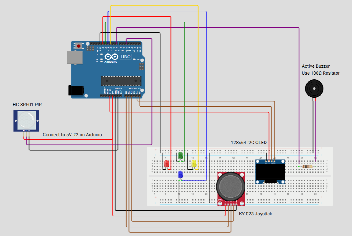
Wires are color-coded for clarity:
BLACK: GND
RED: VCC
PURPLE: DIGITAL PINS
BROWN: ANALOG PINS
LEDs: Each LED pin wire corresponds to its own color (e.g. green digital output wire for green LED).
Wiring
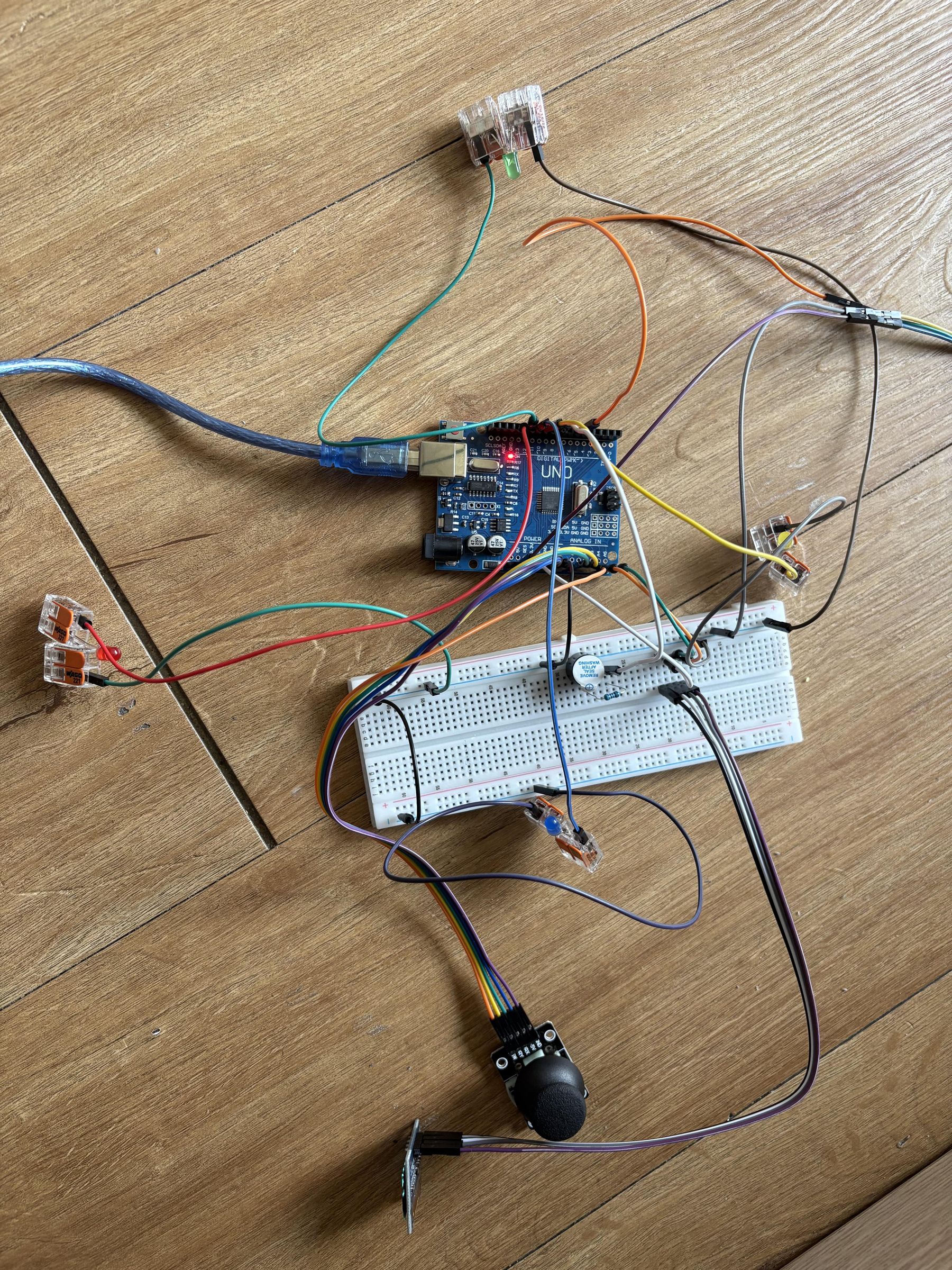
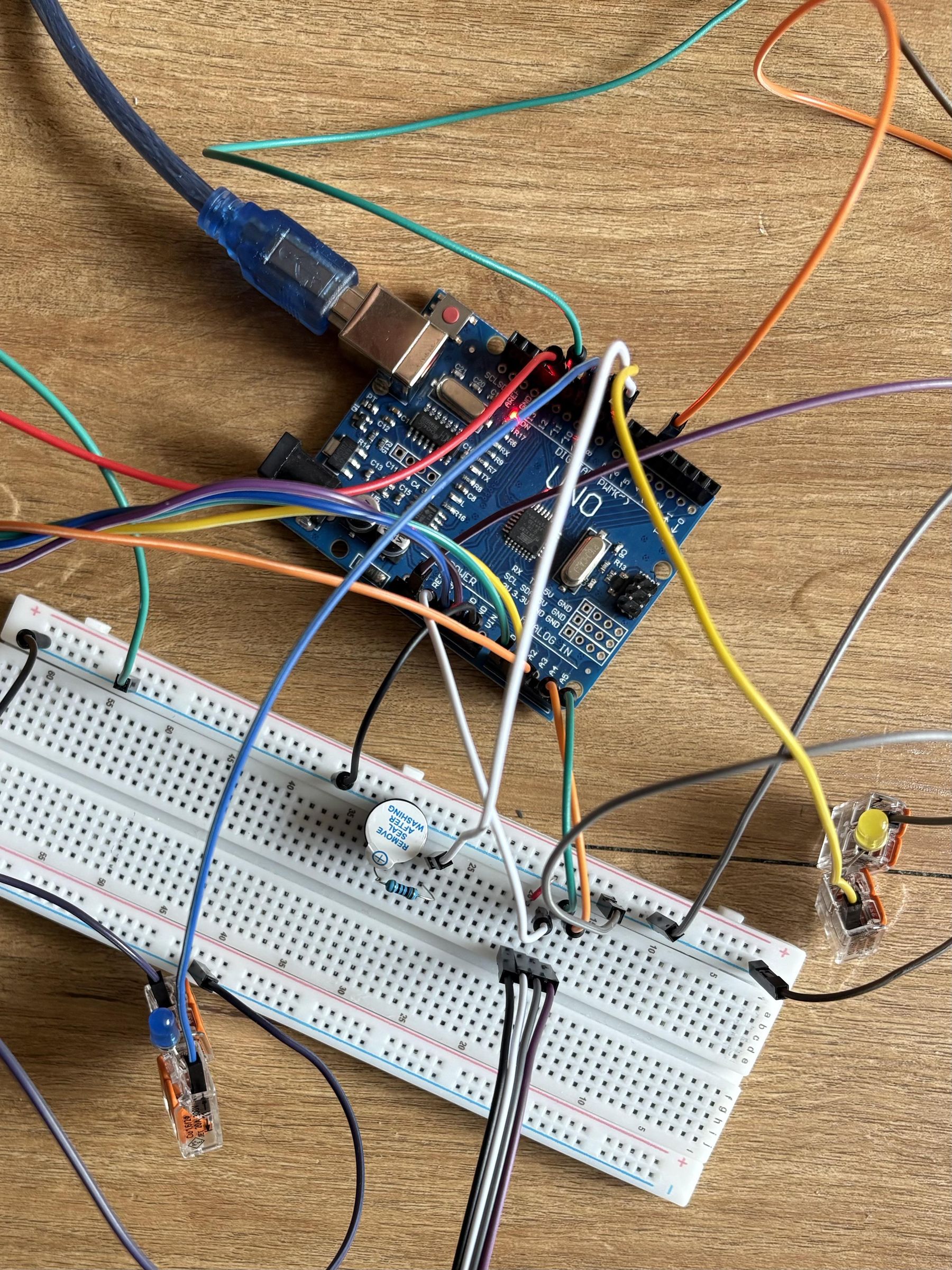
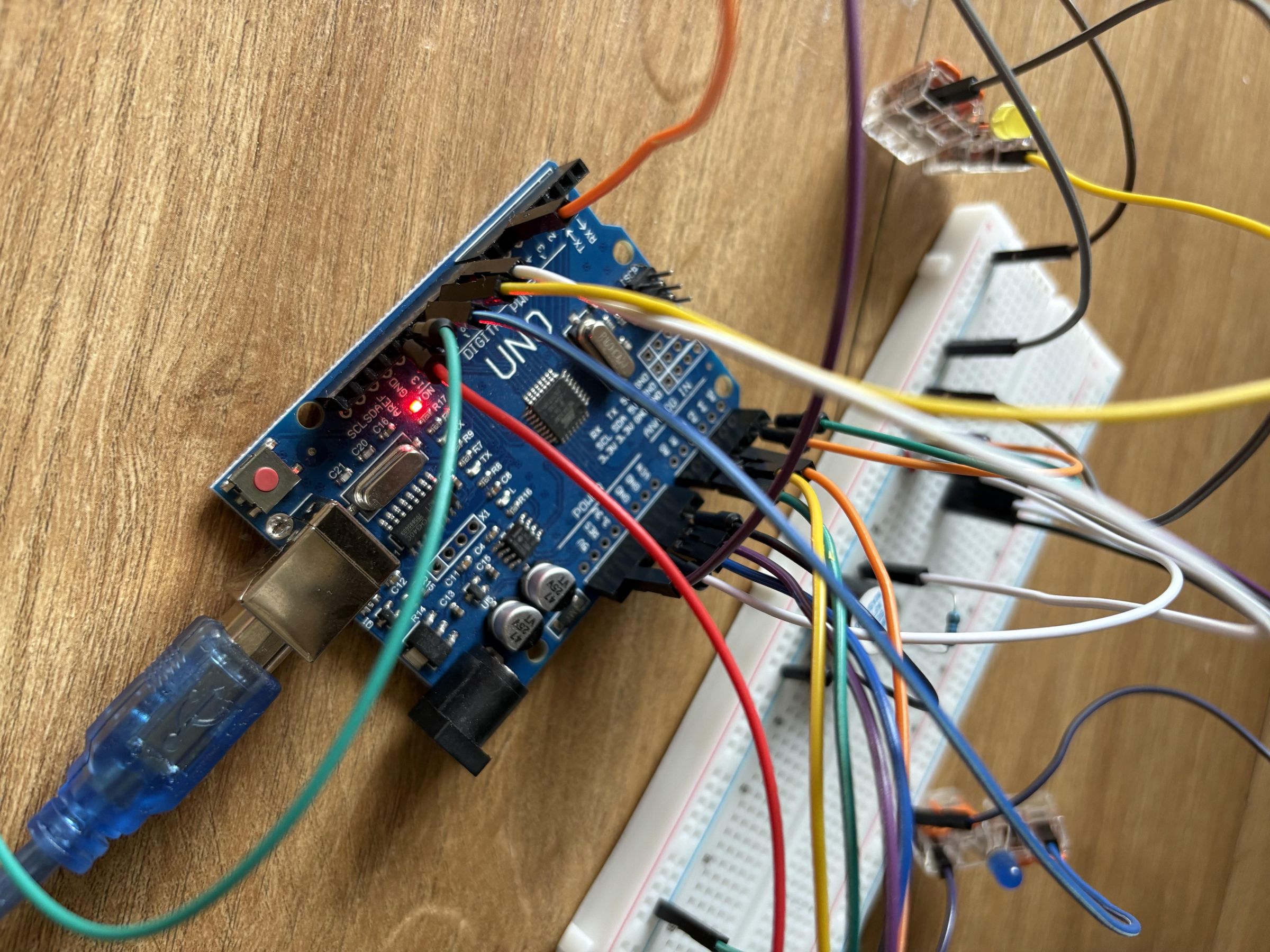
At first, this may seem like a mess of wires, but it gets much easier once you understand the basic premises of Arduino pins and connections.
Power Pins
- VCC (5V/3.3V) powers system
- GND completes circuit
Input Pins
- A0 → Joystick X-axis (analog input)
- A1 → Joystick Y-axis (analog input)
- A2 → Joystick Button (digital input)
- D5 → PIR Motion Sensor (digital input)
Output Pins
- D8 → Buzzer
- D10 → Yellow LED
- D11 → Blue LED
- D12 → Green LED
- D13 → Red LED
Communication Pins (I²C)
- A4 → OLED Display SDA (data)
- A5 → OLED Display SCL (clock)
Building the System
Enclosure
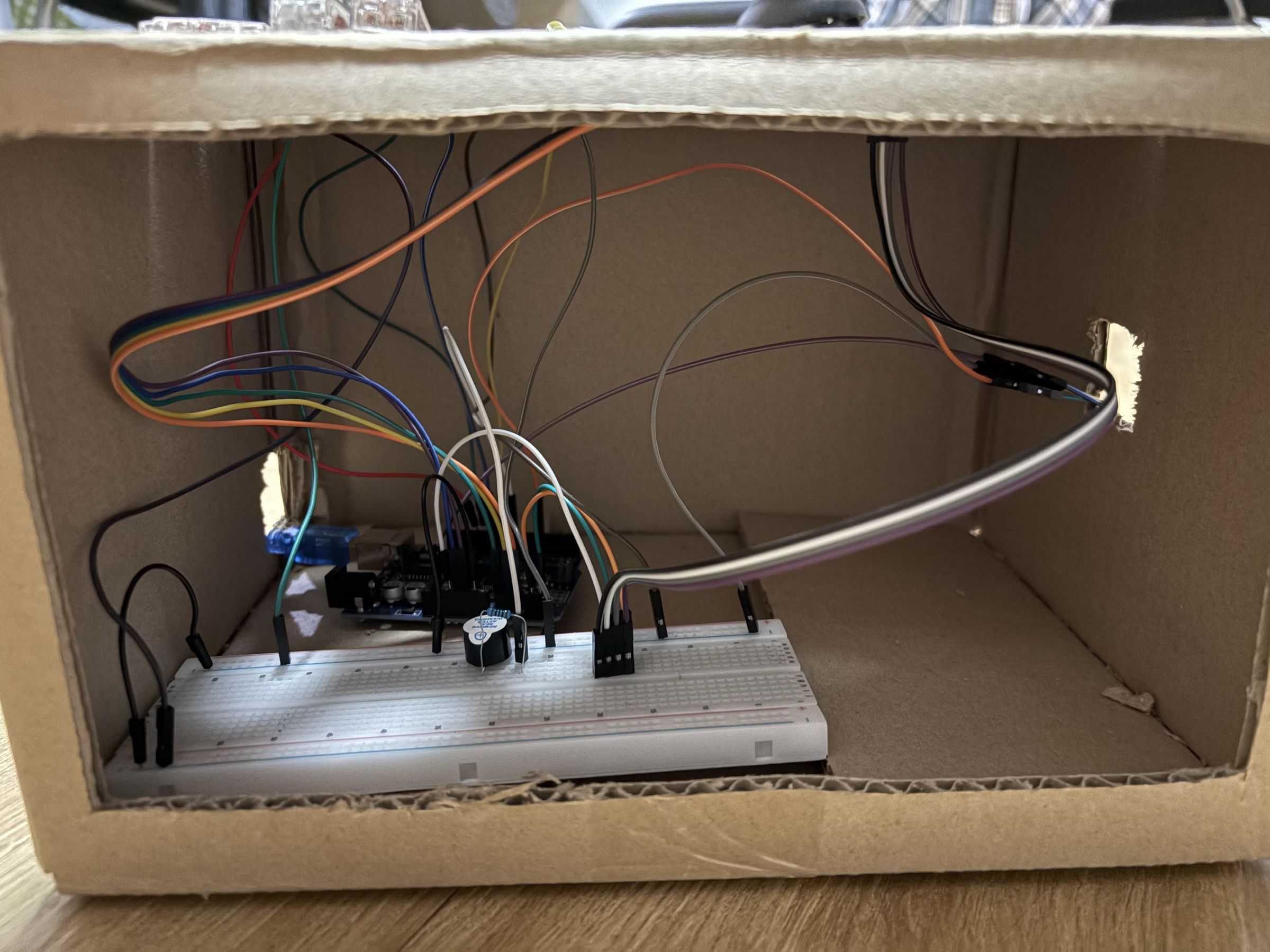
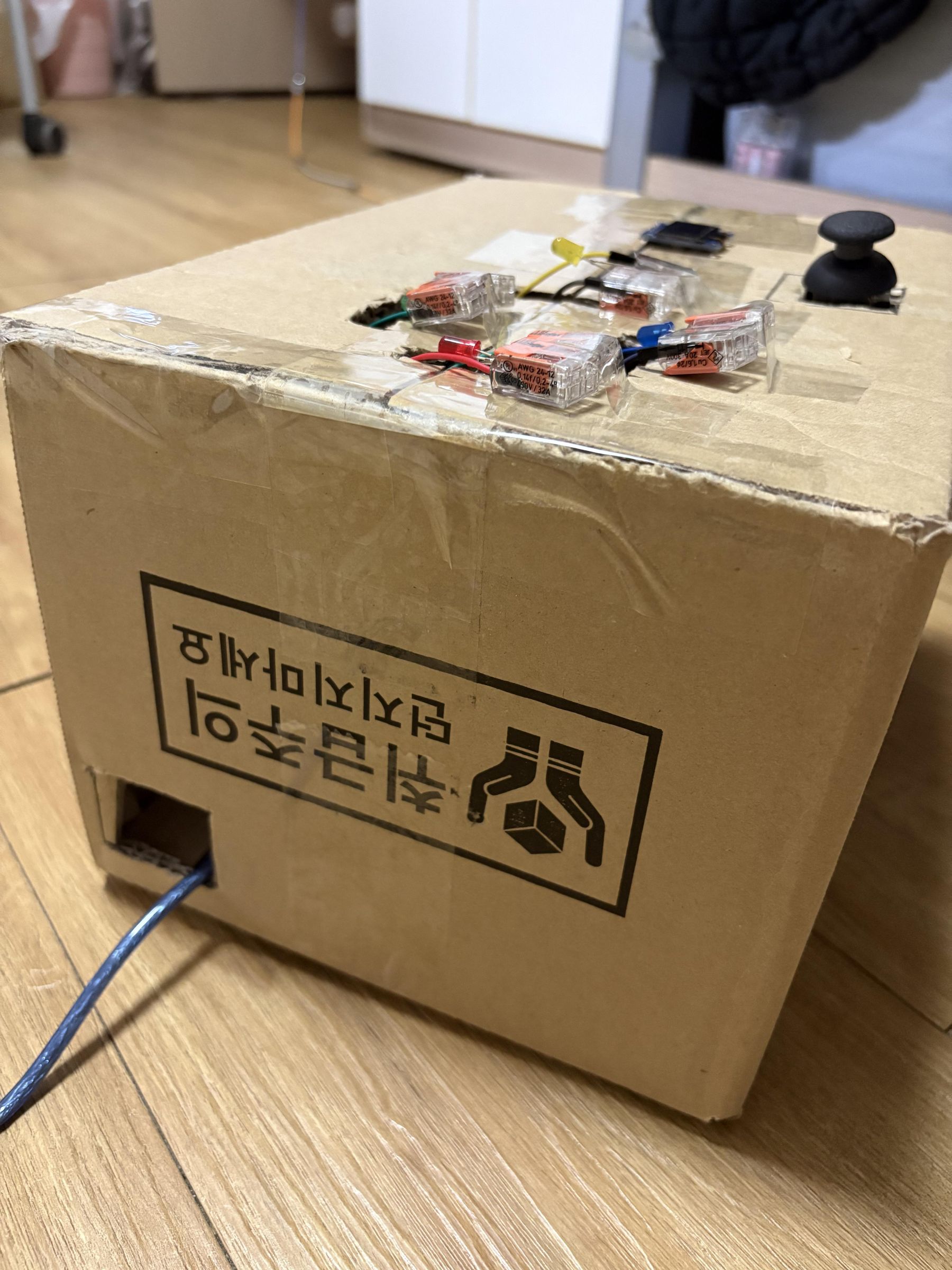
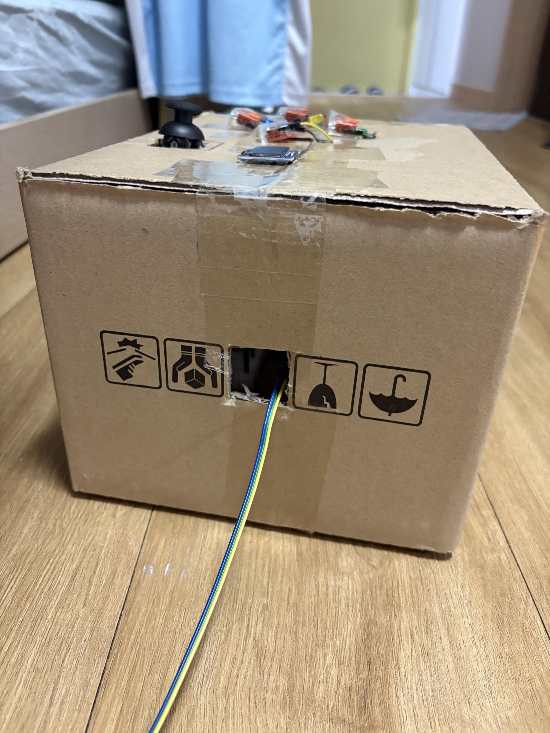
The type of enclosure you build is up to you and depends on your capabilities. Due to time and skill constraints, I used a plain old corrugated cardboard box left over from a previous delivery, and a box cutter to cut holes out for the components and wires. I also cut off the two smaller side flaps and only left the wider top and bottom flaps to make it easier to pull the components through. It was my first time building a physical prototype, so the final result is a little rough around the edges, but it does the job and hides the mess of wires much better!
If you're also planning to use a cardboard box, definitely try to take precise measurements and then leave a slight 0.5-0.7 cm margin of error to make sure you can actually fit the components into the holes. I would also recommend cutting out one face of the cardboard box so you can still see the system and connect the wires or troubleshoot if any problems arise. Secure most, if not all, of your connections before placing the circuit into the box and taping up the top, since it'll be harder to play around with the wires once the system is inside.
GND Wires
Use two black wires for GND, one extending from the GND pin on the Arduino itself to the blue (-) rail on the breadboard, and another extending from that same blue rail to the other blue rail on the opposite side to increase the range of usable space on the breadboard.
LEDs
Since I had to create an enclosure, I moved my LEDs off the breadboard and instead connected each one using two 2-pin Wago connectors and M-M jumper wires so I could extend their range. If you're not planning to create an enclosure, this step is optional and you may connect the LEDs directly to the breadboard following the circuit diagram. Make sure to connect the cathode (shorter negative leg) of the LED to the blue (-) rail on the breadboard (to ground each LED), and the longer anode (positive) leg of the LED to its respective digital output pin on Arduino.
Joystick
The joystick receives power through 5V on the Arduino, and is grounded by direct connection to GND on the Arduino as well. As aforementioned, analog pins A0-A2 are reserved for the rest of the joystick pins. Try to use five moderately long M-F jumper wires to connect the joystick if you're planning to create an enclosure.
OLED
The OLED display receives power through the 3.3V pin, and is grounded via the blue rail on the breadboard. It uses the pins A4 and A5 for communication with Arduino. I connected the OLED to the breadboard with four M-F jumper wires, and since I was creating an enclosure, I then extended the connection to Arduino using four M-M jumper wires plugged into the same columns as the first set of wires. The GND wire used here was one of the very short varieties that keeps the circuit looking clean because it sits flush with the breadboard.
Buzzer
The buzzer connection is fairly simple, as its short cathode (-) leg just needs to be grounded on the blue rail, and its longer anode (+) leg needs to be connected to digital pin 8. It also needs a 100Ω resistor to protect the circuit.
PIR Motion Sensor
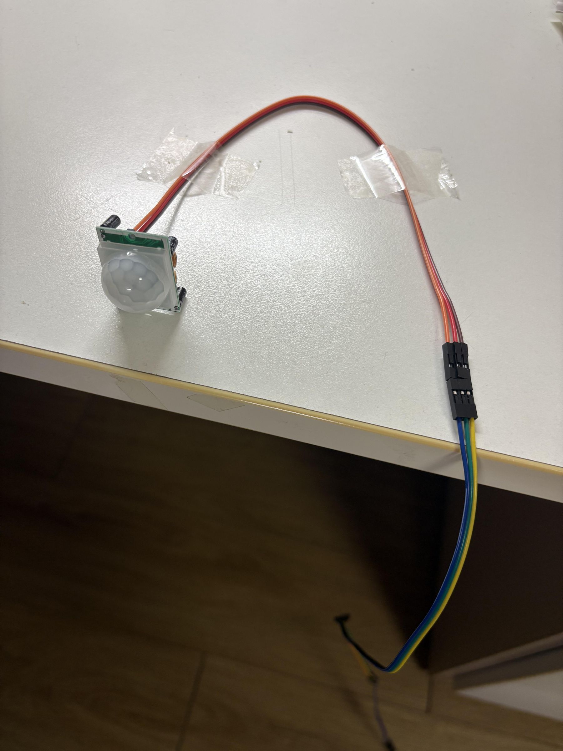
The Arduino Uno model has two 5V pins, so the second one should be connected to the PIR motion sensor. It can either be grounded by connecting to the third GND pin directly on the Arduino, or by connecting the wire to the grounded blue rail on the breadboard. The digital output pin can be connected to any free digital pin on the Arduino; in my case, I just used D5.
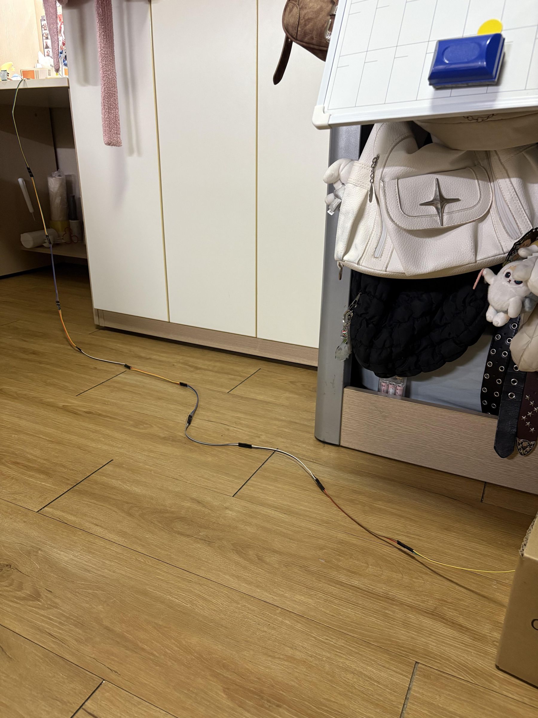
I used 48 M-F jumper wires to extend the motion sensor connection since physical distance played a role in the success of the system. The main components were in a box beside my bed, and the motion sensor was extended to my desk to encourage the user to actually get out of bed for alarm 2.
Reflection
Main Technical Challenges
Designing the Enclosure
This was one of my main struggles, and it took longer than expected to build a functional enclosure for the system. It was difficult to make accurate measurements to cut out holes, and visualize how to actually display the necessary components at the top of the box. I also had to be extra careful with handling the Arduino so that wires wouldn't get bent or dislodged. A couple of wires did pop out a few times, but I noticed immediately and plugged them back in place.
Code Troubleshooting
Since I had multiple components connected to Arduino and running simultaneously, I had to consult with ChatGPT countless times to modify my code. Sometimes, certain components (e.g., the LEDs and buzzers) were synced to each other when they shouldn't have been, or gaps in the code prevented the system from running as intended, or overlapping lines of code blocked other components' functions, and so on. Overall, I had to explain in explicit detail exactly what I needed in order to produce the desired results from AI, which meant I had to have a clear understanding of my goals in the first place.
Loops & Delays
For this system, it was essential to ensure that the loops didn't overlap with each other but instead flowed smoothly in the correct order, and that there was enough delay time between each stage. Therefore, I also invested extra time into refining that to make sure I was getting the right feedback at the right time to create the most natural and intuitive user experience.
OLED UI
Centering the text on the OLED screen and ensuring it was in an appropriate position overall was challenging and required much trial and error before I finally got an understanding of the dimensions of the screen and was able to identify what needed to be modified and how with more ease.
PIR Motion Sensor Testing
The motion sensor I ended up using was different from my original idea. I thought I'd be able to use a regular motion sensor that only tracks movement, but I unknowingly bought a motion sensor that detects infrared radiation. It still worked out well in the end, but I had to wait for the motion sensor to stop detecting residual infrared radiation before running any system tests. Otherwise, the OLED screen would immediately transition from the alarm 1 deactivation screen to the alarm 2 deactivation screen, skipping the countdown. However, since my goal was simply to verify user activity rather than track their exact position at any given time, this method of motion detection was already sufficient to encourage a physical interaction.
What I learned
Arduino
Before taking this course, I had never even heard of Arduino so I had no idea what it was. After this course, I can confidently say I've gained a lot of newfound knowledge and understanding. I'm able to follow tutorials and understand circuit diagrams, as well as the functions of individual pins on the Arduino board. At the beginning of the semester, I felt really anxious when faced with the thought of having to come up with an original idea and follow it through by even building a physical prototype. But now that I understand how it works, it was a lot easier to expand my idea, visualize it, and test it out.
I also learned that troubleshooting an Arduino system for issues is a very tedious process and that sometimes, components that were previously working may suddenly stop working. So, I basically had to activate all of my critical thinking skills and keep trying every possible solution to get this system to work seamlessly whenever any issues came up. I'm quite proud of my problem-solving skills and how far I've come this semester.
Coding
Although this was not a programming course, I feel like I gained a rough understanding of basic coding, specifically with reference to Arduino. Once I got familiar with recurring functions, they started to make more sense to me, and I started to recognize them here and there. I still wouldn't be able to write a code on my own without any help, but it looks a lot less like a mess of random letters and symbols smashed together and more like a logical system now. It was also kind of exciting to see my growth while working with completely unfamiliar software and hardware.
What I would improve if I had more time
Enclosure
The enclosure is definitely one of the more lackluster aspects of my final prototype. I was hoping to create a more polished enclosure, maybe by utilizing a 3D modeling program or making it out of the same kind of cardboard box I actually ended up using. I wanted to try making an arcade machine enclosure since my system resembles an arcade game due to the joystick, LEDs, and OLED interface. However, it proved to be a much bigger challenge than anticipated, and would've required much more precise measurements, skill, and time. It would've looked amazing had I been able to pull it off, but I chose to focus more time and effort on functionality over aesthetics. Therefore, I tried my best to troubleshoot everything, perfect the code and UI, and made sure everything worked exactly as intended by the end.
Wireless Motion Sensor
If I had more time, I might've invested in testing out a wireless motion sensor connection rather than a wired one just to polish the overall look of the project and reduce the number of wires lying around. My project still works fine with a wired PIR motion sensor connection, but it's also worth looking into wireless options to make the project more versatile.
Soldering
Soldering was another skill we briefly touched upon in the course, though we didn't focus extensively on it as it was optional for our projects. I got to try soldering myself a couple of times, but it was a bit more challenging than expected. Once I settled on a final layout for my system and completed the wiring, soldering all the different components to an external board could've saved me the stress of moving the whole system around like a newborn baby just to avoid dislodging any wires. It would've looked cleaner as well, even if I was going to use an enclosure anyway.