Arduino-Controlled 3D-Printed Rocker for a BabyBjörn Bouncer
by CeyhunK3 in Circuits > Arduino
46 Views, 0 Favorites, 0 Comments
Arduino-Controlled 3D-Printed Rocker for a BabyBjörn Bouncer
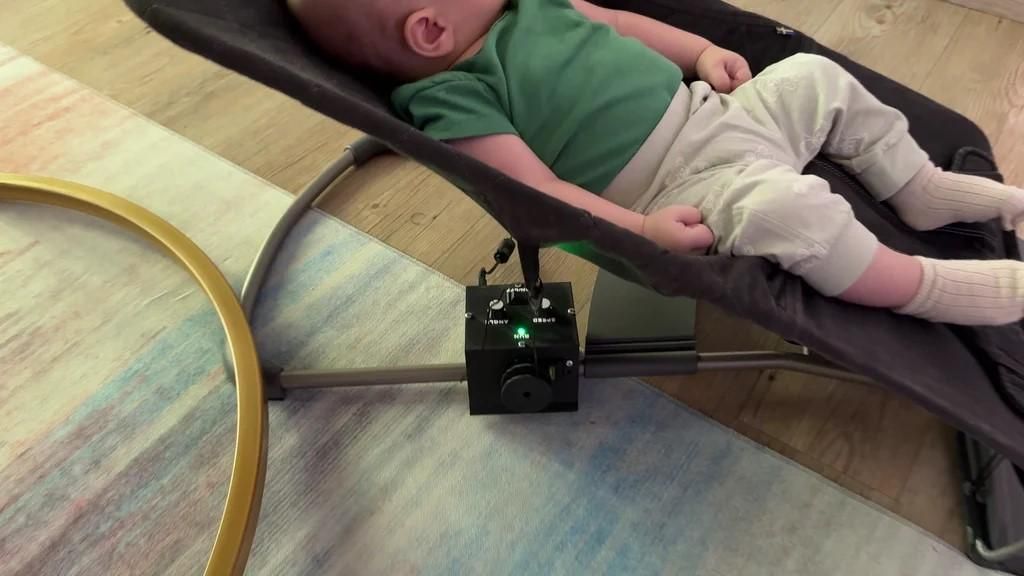

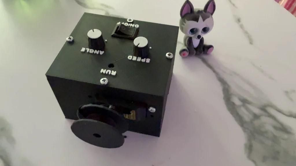
I wanted to automate the rocking motion of our BabyBjörn bouncer without drilling, cutting, or permanently modifying the bouncer itself. What initially seemed like a simple servo project turned into a month-long process of prototyping, testing, and redesigning.
The finished mechanism uses an Arduino Nano-compatible board, a Futaba S3003 servo, two potentiometers, and several custom-designed 3D-printed parts. One potentiometer adjusts the rocking speed, while the other controls the movement range.
The first small servo was not powerful enough, the power system caused several problems, and one mistake resulted in a short circuit. I also redesigned and reprinted the enclosure, servo spool, mounting system, and control knobs several times before reaching the final working prototype.
The complete video below shows the development process, including the failed versions, mechanical redesigns, electronics, assembly, and final test.
https://www.youtube.com/watch?v=fjWGQE94p3s
The STL files, Arduino code, and wiring diagram are available for free at the end of this Instructable.
Safety notice: This is an experimental DIY prototype, not a certified baby product. It must never be used unattended or relied upon as a safety or sleep device. A bouncer is not a normal sleep surface. Anyone recreating this project is responsible for evaluating the mechanical and electrical risks of their own build.
Supplies
Electronics:
- Arduino Nano-compatible board
- Futaba S3003 standard servo
- 2 potentiometers for speed and movement-range control
- External regulated 5 V / 2 A power supply
- 470 µF electrolytic capacitor
- Hook-up wires and connectors
- USB cable for programming the Arduino
3D-Printed Parts:
- Main electronics enclosure
- Enclosure cover
- Servo spool
- Bouncer mounting parts
- Potentiometer control knobs
- Servo mounting parts
Tools:
- 3D printer
- Soldering iron and solder
- Screwdrivers
- Wire cutter and stripper
- Computer with the Arduino IDE
The STL files, Arduino sketch, and wiring diagram are linked in the final step.
How the Mechanism Works
The mechanism creates a controlled back-and-forth rocking motion using a servo-driven spool. As the servo rotates between two adjustable positions, the spool pulls and releases the connecting line attached to the bouncer mechanism.
An Arduino Nano-compatible board controls the servo movement. The two potentiometers provide direct manual adjustment:
- The first potentiometer controls the rocking speed.
- The second potentiometer controls the servo travel and therefore the movement range.
This makes it possible to change both settings without reconnecting the Arduino or modifying the code.
The mechanism is mounted externally and does not require drilling, cutting, or permanently modifying the BabyBjörn bouncer. The enclosure holds the controller and electrical connections, while the servo, spool, and mounting parts transfer the motion to the bouncer.
The Futaba S3003 provided enough torque for the final prototype, although it is not silent during operation.
The First Prototype and Why It Failed
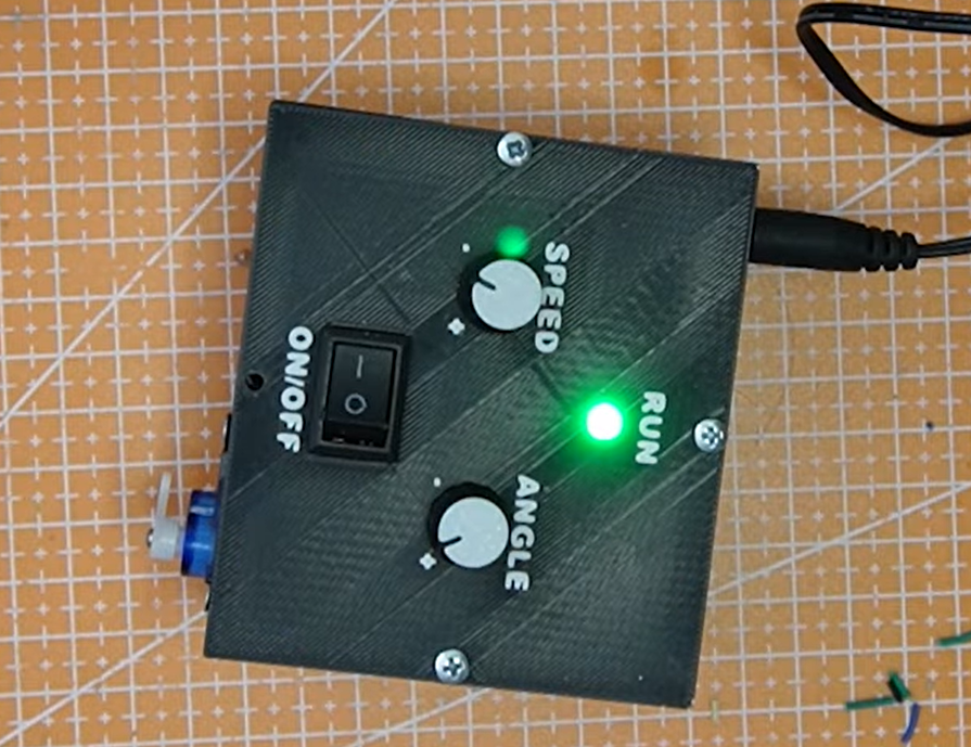
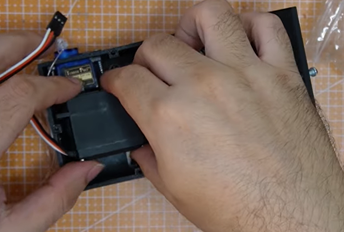
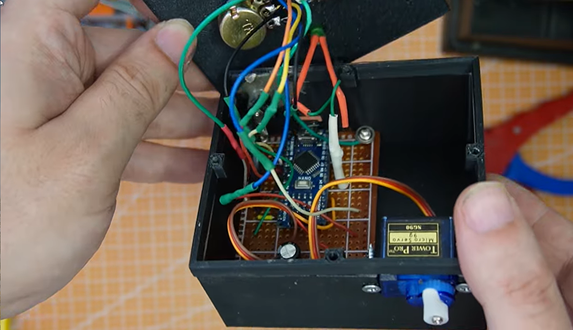
My first prototype used a small SG90 micro servo. It worked when tested without a load, but it was not powerful enough to move the bouncer consistently once the complete mechanism was connected.
The problem was not only the weight being moved. The spool diameter, the mounting position, and the changing mechanical load throughout the rocking motion all affected the amount of torque required.
This first version was useful because it confirmed that the basic idea could work, but it also showed that a stronger servo and a more rigid mounting system were necessary.
I replaced the SG90 with a Futaba S3003 standard servo. The larger servo provided significantly more usable torque, but changing the servo also meant redesigning the spool, mount, and enclosure around its larger dimensions.
This became the first major redesign of the project.
Power Problems and a Short Circuit
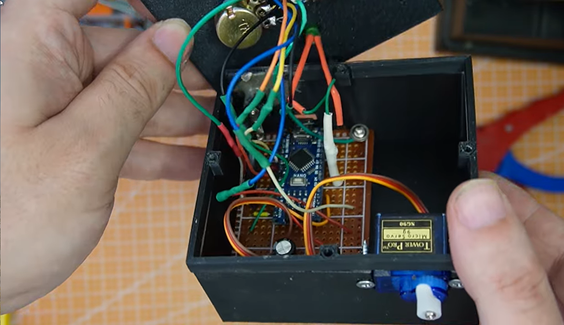
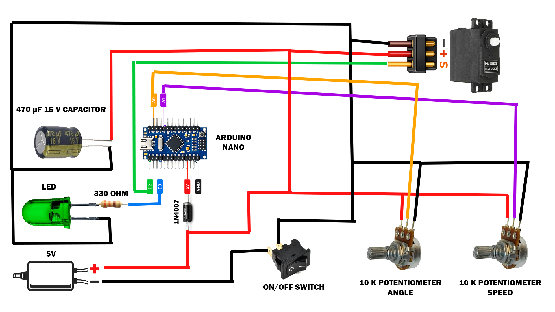
The stronger servo solved the torque problem but introduced a new challenge: power.
A servo can draw a relatively high current while starting, changing direction, or working under load. During the early tests, an inadequate power arrangement caused unstable operation and made the system unreliable.
For the final prototype, I used an external regulated 5 V / 2 A power supply. The servo receives power from this external supply rather than relying on the Arduino's USB connection to provide the required current.
The Arduino and servo must share a common ground so that the servo control signal has the same electrical reference. I also added a 470 µF electrolytic capacitor across the power supply lines to help reduce short voltage drops caused by sudden servo movement.
During one of the prototype wiring changes, I accidentally created a short circuit. Fortunately, I discovered it before continuing with the mechanical tests, but it was an important reminder to disconnect the power before changing any connections and to verify polarity with a multimeter before switching the system on.
Follow the wiring diagram carefully, especially the polarity of the external power supply and electrolytic capacitor. Wiring errors can damage the Arduino, servo, power supply, or connected computer.
Designing and Printing the Mechanical Parts
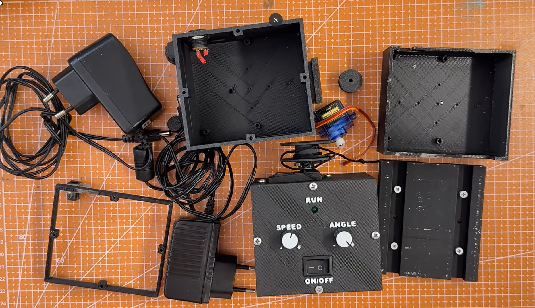
Most of the mechanical system was designed specifically for this project and produced with a 3D printer. The printed components include the electronics enclosure, servo spool, mounting parts, servo support, and potentiometer knobs.
The first printed parts proved the general concept, but they did not form a sufficiently rigid and practical final assembly. Changing from the small SG90 servo to the larger Futaba S3003 also made the original spool, servo mount, and enclosure dimensions unusable.
Several parts went through multiple versions. I adjusted the spool geometry, reinforced the mounting arrangement, reorganized the internal space for the electronics, and changed the enclosure so that the potentiometers and wiring could be installed more cleanly.
Each iteration followed the same process:
- Measure the relevant components and mounting points.
- Modify the 3D model.
- Print and test the part.
- Check alignment, clearance, and mechanical stability.
- Redesign any part that did not work reliably.
The final design keeps the mechanism external to the bouncer. It can be installed without drilling or permanently altering the original frame.
All printable STL files are available through the link in the final step.
Assembling the Electronics
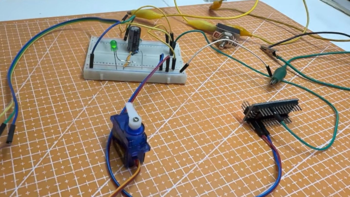
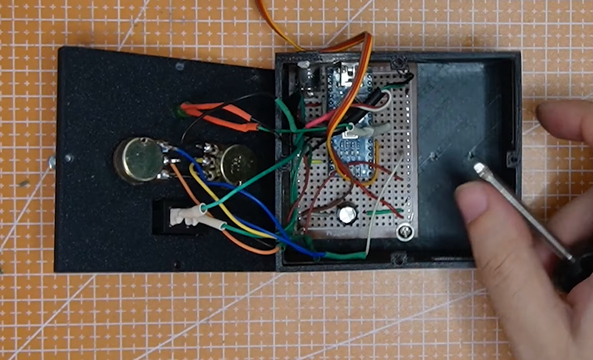
Install the Arduino Nano-compatible board, potentiometers, capacitor, and wiring inside the printed enclosure according to the wiring diagram.
In my build, the two potentiometers are connected to the Arduino's analog inputs. One is used for speed control, while the other sets the servo movement range. The servo control wire is connected to a digital output pin.
The servo is powered by the external regulated 5 V supply. Do not attempt to power a loaded servo from the Arduino's 5 V pin or USB connection. Connect the ground of the external supply to the Arduino ground so that the Arduino and servo share a common electrical reference.
Connect the 470 µF electrolytic capacitor across the 5 V and ground lines, observing its polarity. The negative side of an electrolytic capacitor is normally marked with a stripe.
Before connecting the servo:
- Disconnect the external power supply.
- Check every connection against the wiring diagram.
- Verify the power-supply polarity.
- Check for accidental shorts with a multimeter.
- Secure exposed connections so they cannot touch inside the enclosure.
Keep the power and signal wiring clear of the moving spool and connecting line. After verifying the circuit, close the enclosure without pinching any wires.
Uploading the Arduino Code and Testing the Controls
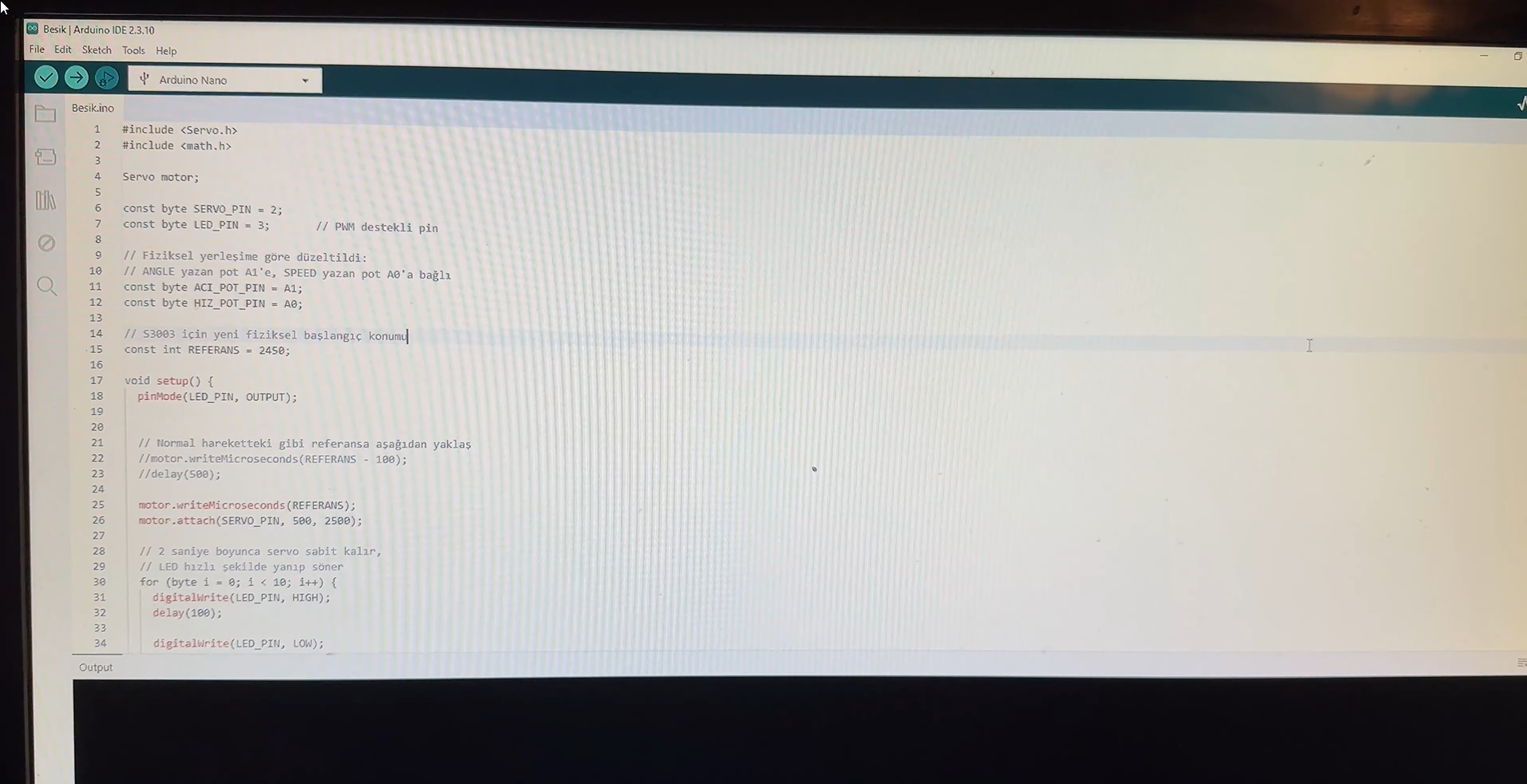
Open the supplied .ino file in the Arduino IDE and connect the Arduino Nano-compatible board to the computer with a USB cable.
Select the appropriate board, processor, and COM port for your particular Nano-compatible board, then compile and upload the sketch. Some compatible boards may require a different processor or USB-serial driver than an official Arduino Nano.
The program continuously reads the two potentiometers:
- The speed control changes the delay between small servo movements.
- The range control changes how far the servo travels during each rocking cycle.
Before connecting the mechanism to the bouncer, test the electronics without a mechanical load.
- Place the range control at its lowest setting.
- Make sure the spool and connecting line are clear.
- Apply power to the system.
- Slowly adjust the range and observe the servo movement.
- Test the speed control at several positions.
- Confirm that the servo remains within the intended movement limits.
If the servo moves in the wrong direction, vibrates continuously, reaches a hard mechanical stop, or causes the Arduino to restart, disconnect the power immediately and recheck the wiring, power supply, and mechanical alignment.
Do not install the servo horn or spool in a position that allows the servo to force the mechanism beyond its safe physical range.
Installing the Servo, Spool, and Mount
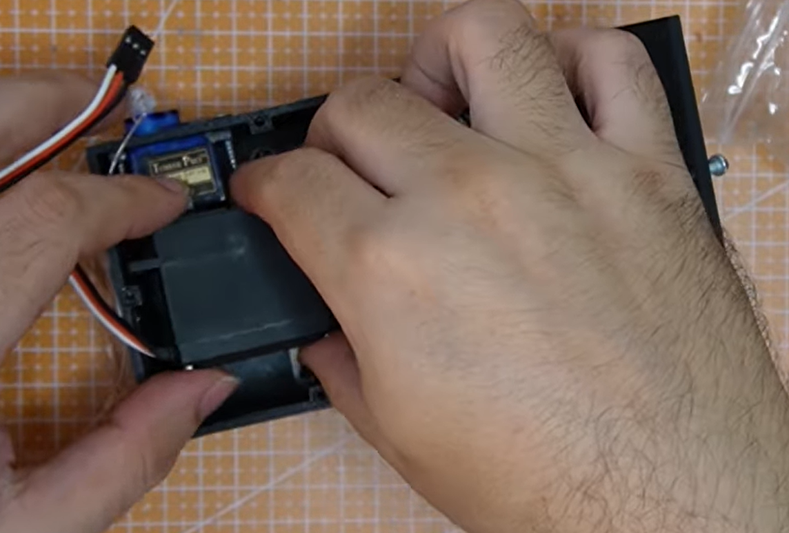
After testing the electronics without a load, install the Futaba S3003 in its printed mount and secure it so that it cannot rotate or shift under load.
Attach the printed spool to the servo in the correct orientation. Before tightening it completely, move the servo to its neutral position using the controls. This helps prevent the mechanism from starting too close to one of the servo's physical limits.
Position the external mounting parts on the bouncer without drilling, cutting, or permanently altering the original frame. Route the connecting line between the spool and the moving section of the bouncer, following the arrangement shown in the photos.
Check the installation carefully:
- The servo and mount must remain stable during movement.
- The connecting line must run freely without rubbing against a sharp edge.
- The spool must not contact the enclosure or mounting parts.
- The wiring must stay clear of all moving components.
- The mechanism must not restrict the bouncer's normal movement.
Begin with the movement-range control at its minimum setting. Run the mechanism without a child in the bouncer and gradually increase the range while observing the spool, line, mount, and frame.
If the line becomes excessively tight, the servo reaches a hard stop, or any printed component bends or shifts, disconnect the power and adjust the installation before continuing.
Final Test and Results
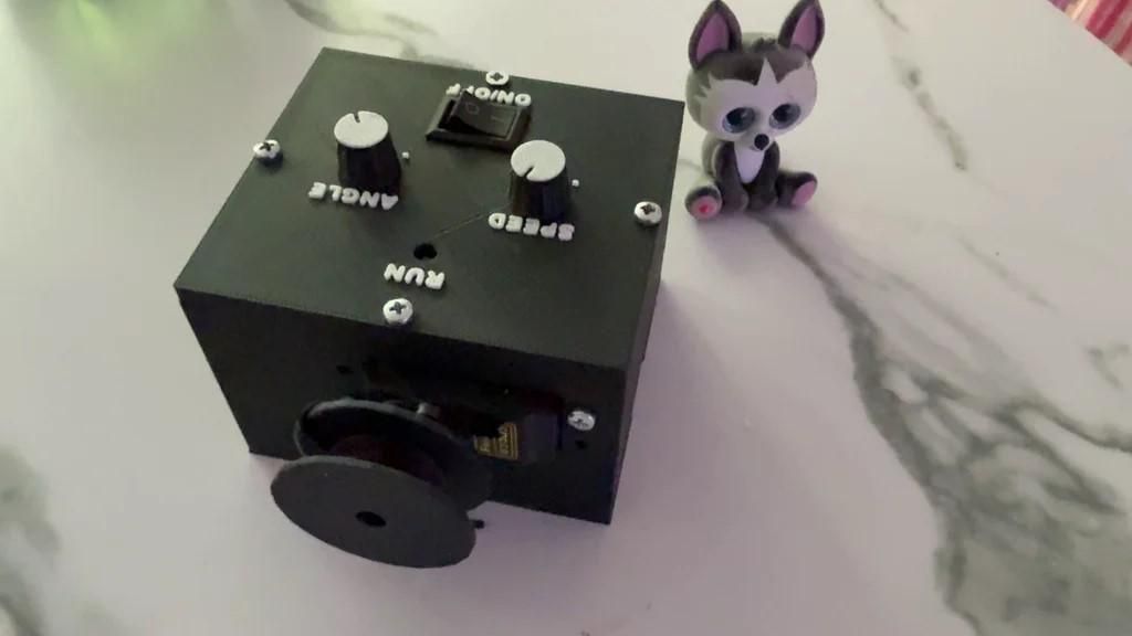
After approximately one month of prototyping and redesigning, the final mechanism produced a consistent and adjustable rocking motion.
The two potentiometers made it possible to change the behavior of the system without modifying or uploading the Arduino code again. One control adjusts the rocking speed, while the other changes the servo travel and therefore the movement range.
During the final test, I started with the lowest movement range and gradually increased it while checking the servo, spool, connecting line, printed mounts, and enclosure. The larger Futaba S3003 servo provided enough torque for the mechanism, and the redesigned printed parts remained stable during operation.
The finished prototype achieved the main goals of the project:
- Adjustable rocking speed
- Adjustable movement range
- No permanent modification to the bouncer
- A compact enclosure for the electronics and controls
- Reproducible parts made with a 3D printer
- Simple manual operation without reconnecting a computer
The system is not silent. The servo produces noticeable mechanical noise while moving, especially when changing direction or operating under load. This is a limitation of the current prototype rather than something hidden by the final result.
This project should be considered a successful experimental prototype, not a finished or certified consumer product. Future improvements could include a quieter actuator, improved motion transmission, and additional protection for the moving components.
Project Files and Safety Notes
The complete project resources are available free of charge on Thingiverse:
https://www.thingiverse.com/thing:7393849
The download includes:
- 3D-printable STL files
- Arduino .ino source code
- Wiring diagram
- Additional project information
The Arduino code is shared under the MIT License. Please check the project page for the licenses and details applying to the remaining files.
The complete build video documents the full month-long process, including the first underpowered servo, power problems, the short circuit, mechanical redesigns, assembly, and final working test:
https://www.youtube.com/watch?v=fjWGQE94p3s
Safety Notes
This mechanism is an experimental DIY prototype and not a certified baby product or safety device. It has not been tested or approved by BabyBjörn or any independent safety organization.
Never use the mechanism unattended. Keep hands, clothing, cables, and other objects away from the spool, connecting line, servo, and all moving parts. Disconnect the power before adjusting the wiring or mechanical components.
A bouncer is not a normal sleep surface. Follow the bouncer manufacturer's original instructions, age and weight limits, and all applicable safe-sleep guidance. Anyone reproducing or adapting this project is responsible for assessing the electrical, mechanical, and operational risks of their own build.
This project is shared as documentation of a personal maker experiment, not as a recommendation to replace active adult supervision.