Arduino Drawing Car Project

Our team ( Katherine, Adriana, Rodah) Created this instructable to show what we have learned from our ME 208 Course at the university of Kansas instructed by Dr. Wilson.
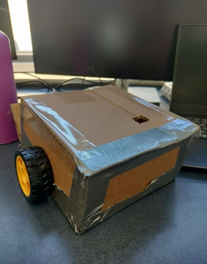
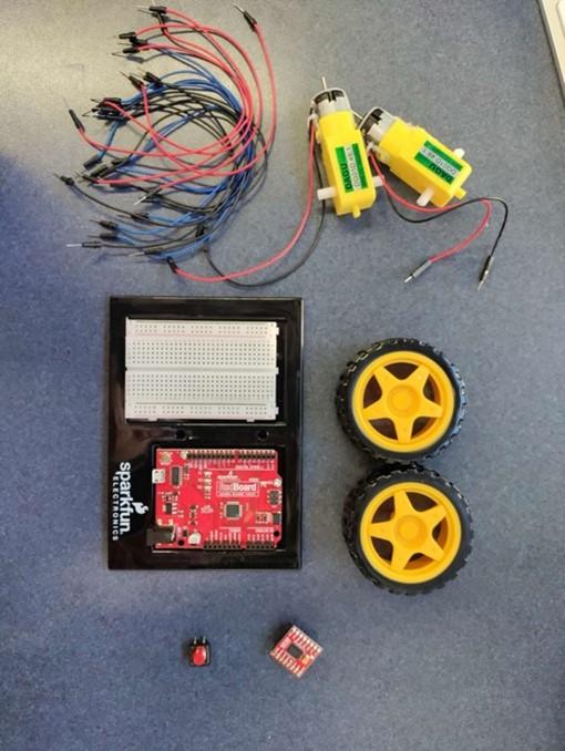
This robot uses a cardboard box as the body, everything inside is from Sparkfun tool kit. It also complies with the 4H robotics requirements for the Douglas County Fair. The difficulty of constructing the robot was not too difficult to put together. Understanding and building is the more difficult part but accomplishable.
The car can drive forward/backwards and stay within a specific perimeter. With the code functions we created to draw our piece of paper.
Time needed to build the drawing bot will only take a few hours.
Supplies

You will need the SparkFun inventors kit v4.1
Tools from kit;
· 1 Arduino Uno
· 1 Small Breadboard
· 1 Motor Driver
· 1 Button
· 1 Medium Cardboard Box
· 1 Marker
· 1 Large Sheet of Paper
· 2 Hobby Gearmotors
· 2 Wheels
· 15 Jumper Wires
· 1 Battery Pack
· 4 AA Batteries
Link : SparkFun Inventor's Kit for Arduino Uno - v4.1 - KIT-15631 - SparkFun Electronics
Building


Tools needed:
Breadboard
Arduino Uno
Push button
Moter drive
3 wires
We first form a connection from the blackboard to the Arduino Uno
- The positive supplies power, connect to (5v)
- The negative is where you connect the ground (GND)
- You will than connect another wire under the button (number 2 slot) to the negative side to ensure the circuit is properly grounded.
Circuit Board Pt2

.jpg)


Building on to our Circuit Board: Notes added to the images for corresponding steps.
First Attach a blue wire (under number 4) and connect it under the button to digital pin 2
- This forms a connection to know when the button is pressed
second Attach another red wire under the motor drive (under 26) to the positive red slot (red)
- This is to supply power to the motor drive
Third connect a black wire on top (under 22) of the motor drive to the negative side slot(red)
- this allows the electricity to flow from the positive side (where it's supplied) through the motor, and then back to the negative side.
Fourth connect another wire on top(under 28) of the motor to the positive side slot (red)
- supplies power
Fifth Connect a red wire on top of the motor drive (under 29) to the VIN (Voltage In)
- supplies power to the circuit board without any regulation until you provide a voltage
Sixth image shows the full complete process
Circuit Board Pt3


We are going to continue to build on the connections around our motor drive
Notes included in the images for corresponding steps
First
Under the motor driver pin a red wire to 23 and the end of the wire to 10
second
Under the motor driver pin a blue wire to 24 and the end of the wire to 9
Third
Under the motor driver pin a blue wire to 26 and the end of the wire to 8
Fourth
Under the motor driver pin a blue wire to 27 and the end of the wire to 13
Fifth
Under the motor driver pin a blue wire to 28 and the end of the wire to 12
sixth
Under the motor driver pin a black wire to 29 and the end of the wire to 11
We have built connections to control two different motors
11-13 is one motor
8-10 is another motor
Adding the Gearmotors


We are going to attach one gear motor near our motor drive
- The red side of the gear motor will be attached to the top of the motor drive pinned to 23
- second, the black side will be pinned right next to it on 24
Notes added to the Visal images
Another gearmotor will be attached
The black side of the motor will be attached in the same location on top of 24
The red side will be attached next to it (25)
Notes on visual images
Code Elements
- Motor Control Setup:
- The code defines the pins used to control two motors (Motor A and Motor B) connected to the drawing bot.
- Each motor has two pins for direction control (AIN1, AIN2, BIN1, BIN2) and one pin for speed control (PWMA, PWMB).
- Button Setup:
- The code defines a pin for a button that controls the movement of the drawing bot.
- The button pin is set up as an input pin with an internal pull-up resistor to ensure a stable reading when the button is not pressed.
- Setup Function:
- In the setup() function, the motor pins and button pin are initialized.
- Motor pins are set as output pins to send signals to the motor driver.
- The button pin is configured as an input pin with an internal pull-up resistor to detect button presses.
- Main Loop Function:
- The loop() function continuously runs the main program logic.
- It reads the state of the button using digitalRead(button) to determine if the button is pressed.
- If the button is pressed, the drawing bot performs a sequence of movements:
- Forward for 2.5 seconds, then turn for 1 second, forward for 4 seconds, turn for 2 seconds, and finally move backward for 3 seconds.
- Each movement is executed by setting the appropriate motor pins and applying PWM (pulse-width modulation) to control motor speed.
- If the button is not pressed, both motors are stopped to halt the movement of the drawing bot.
- A small delay is added at the end of the loop to avoid rapid state changes.
Downloads
Electrical Components

Link to the code included
Downloads
Explaining the Code
Link to how the code works is here:
https://www.instructables.com/Drawing-Bot-Explaining-the-Code/
Video
Link to the video: VID_20240411_093640.mp4.
This video is like a detailed guide for building the circuit part of your project. First, make sure to switch to English if you're not already there. The video starts by showing how to connect the motors, explaining each step clearly. Then, it moves on to setting up the motor drive, making sure everything is hooked up properly for the motors to work smoothly. After that, it shows how to set up the button and control the motors, so you can make your robot move just the way you want. And by the end, everything fits together perfectly. You can watch it at your own pace and follow along to create your very own drawing robot.