Arduino Home Security System
by AkshayGupta in Circuits > Arduino
377 Views, 1 Favorites, 0 Comments
Arduino Home Security System


Idea:
Welcome to this Instructables guide! The home security system built with Arduino offers a reliable and cost-effective solution for protecting your home. With the rising number of break-ins and burglaries, which have increased dramatically in recent years, having an efficient security system is essential to ensure safety. This system detects motion through a sensor, automatically taking a picture to capture any potential intruder. As soon as motion is detected, an alarm is triggered to alert the homeowner of a possible threat, while an LED light flashes and a picture is captured of the intruder. By integrating these features, the Arduino-based home security system helps deter criminals, providing peace of mind to homeowners and enhancing overall security.
What the Project Does:
- Detects Motion: The ultrasonic sensor monitors the area for movement.
- Sounds an Alert: When motion is detected, a buzzer is activated to provide an audible alarm.
- Lights Up: An LED turns on to indicate motion detection visually.
- Takes a Picture: A signal is sent to the computer to capture an image of the detected activity.
Why Build This Project?
This project introduces you to using Arduino with sensors and actuators in a practical scenario. It demonstrates how to integrate different components to create a functional system. Whether you're looking to enhance your understanding of electronics or add a DIY touch to your security setup, this project is a fun and educational experience.
Key Features:
- Real-time motion detection using an ultrasonic sensor.
- A buzzer and LED provide immediate feedback upon detecting motion.
- An interface with a computer enables image capture for documentation or surveillance.
Research:
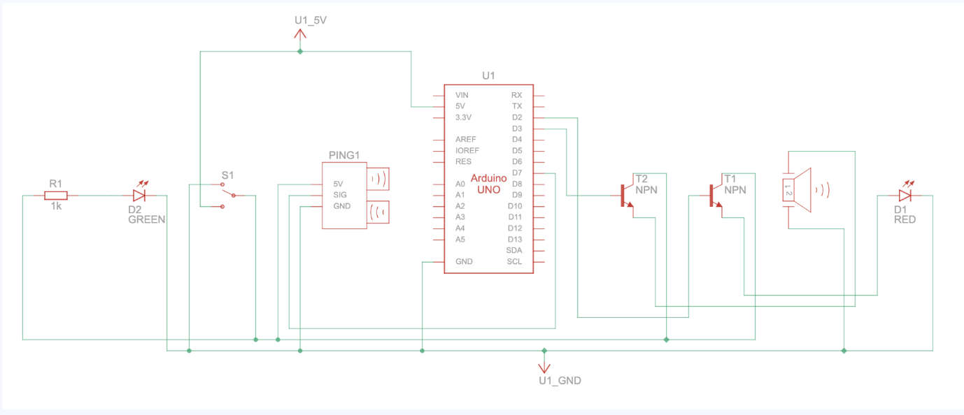
For the home security system, several components were selected to ensure functionality and efficiency. The Arduino Uno R3 was used as the central controller, chosen for its versatility and compatibility. The ultrasonic distance sensor detects motion, while the red and green LEDs indicate system status. A piezo buzzer provides an audible alarm when motion is detected. A slide switch allows easy activation and deactivation of the system, and a 1k ohm resistor helps regulate current flow. An NPN transistor (BJT) was used to amplify signals for the LEDs and buzzer. These components were chosen to create a reliable and affordable security solution.
Supplies

1. Arduino Uno R3 x1
2. Ultrasonic Distance Sensor x1
3. Red LED x1
4. Green LED x1
5. Piezo x1
6. Slide Switch x1
7. 1k ohm Resistor x1
8. NPN Transistor (BJT) x2
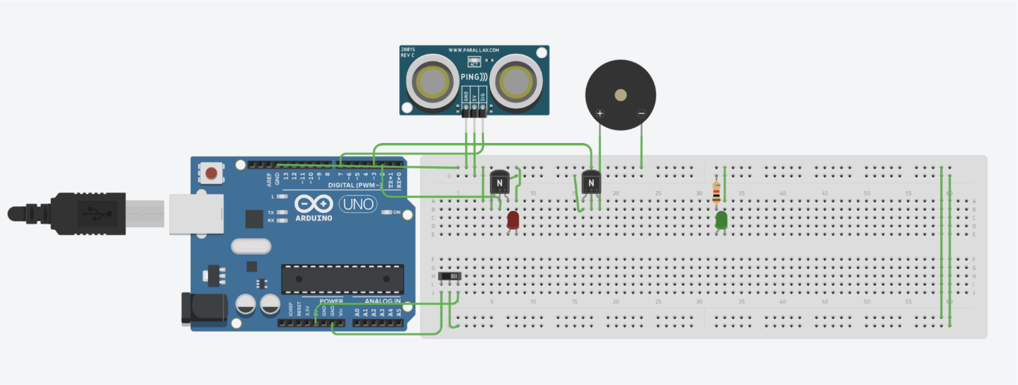
Initial Wiring

1. Connect both GND rails of the breadboard
2. Connect both power rail of the breadboard
Connect the Ultrasonic Sensor

1. Place the ultrasonic sensor on the breadboard with the pins aligned horizontally.
2. Connect the GND pin of the sensor to the GND rail on the breadboard.
3. Connect the VCC pin of the sensor to the 5V rail on the breadboard.
4. Connect the TRIG pin of the sensor to digital pin 8 on the Arduino.
5. Connect the ECHO pin of the sensor to digital pin 7 on the Arduino.
Connect the Peizo

- Place the piezo buzzer on the breadboard with its positive (+) and negative (-) legs exposed.
- Connect the positive leg (+) of the buzzer to one terminal of a 1kΩ resistor.
- Connect the other terminal of the 1kΩ resistor to the collector (C) of the NPN transistor (e.g., 2N3904 or similar).
- Connect the emitter (E) of the NPN transistor to the GND rail on the Arduino.
- Connect the base (B) of the NPN transistor to digital pin 3 on the Arduino through a 220Ω resistor. This resistor limits the current flowing into the transistor's base.
- Connect the negative leg (-) of the buzzer directly to the GND rail on the arduino.
Connect the Red Led and NPN Transistor and VCC/GND

1. Place the red LED on the breadboard.
2. Connect the longer leg (anode) of the red LED to the collector pin (middle pin) of the first NPN
transistor.
3. Connect a 220Ω resistor from the shorter leg (cathode) of the LED to the GND rail on the
breadboard.
4. Connect the 5V pin from the Arduino to the VCC rail on the breadboard
5. Connect the GND pin from the Arduino to the GND rail on the breadboard
Connect the Green Led

Wire the LED
1. Place the green LED on the breadboard.
2. Connect the longer leg (anode) of the green LED to the power rail using a 220Ω resistor
3. Connect the shorter leg (cathode) of the LED to the GND rail on the breadboard.
Upload the Code
- Go to this github link and download all the code: https://github.com/AkshayG99/ArduinoHomeSecuritySystem/tree/main
- Download a compiler which supports python such as VS Code
- Upload the "summative_2.ino" file in the arduino IDE
- Upload the "all.py" file in VS Code
Start the Project
- Connect the Arduino
- Run the "summative_2.ino" file in the arduino IDE
- Change the port in this line: arduino = serial.Serial("/dev/tty.usbserial-14110", baudrate=9600, timeout=5)
- Run the "all.py" file in VS Code using "python3 all.py" on macOS/Linux and "python all.py" on Windows