Arduino IOT: Temperature and Humidity ( With ESP8266 WiFi)
by Ardumotive_com in Circuits > Arduino
130199 Views, 394 Favorites, 0 Comments
Arduino IOT: Temperature and Humidity ( With ESP8266 WiFi)


Hello everyone! I am Michalis Vasilakis from www.ardumotive.com and in this Instructables I will show you how to make your own Internet Of Things (IOT) thermometer by using the Arduino uno board.
You can use it at home, at the office, or anywhere there is an internet connection, for indoor or outdoor data logging. Ιn this project we will use the DHT-22 sensor to take temperature (oC) and humidity (%) values every one hour. For the internet connection we will use the ESP8266 WiFi (serial) module because it's small,cheap and easy to use, and for data logging we will use the open data platform for the Internet of Things "ThingSpeak" (www.thingspeak.com).
You can also make monthly or yearly average charts and see how your climate change affects your area!
So, let's get started!
P.S.: Updates and Q&A here: http://www.ardumotive.com/iot-wifi-temp-and-humidity.html
What We Will Need

For this project we will need:
- Arduino uno board (or any other Arduino board) (link)
- Small breadboard (or an breadboard shield) (link)
- DHT-22 sensor (link)
- ESP8266 WiFi serial module (link)
...and off course some breadboard wires.
Update - Note:
Some users reported me that you may need an external 3.3V power supply for powering up the ESP8266. You can try to use the LD1117V33 (LD33V3) voltage regulator.
The Circuit


The connections are pretty easy, watch the above image with the breadboard circuit schematic.
Notes:
DHT-22
- DHT-22 Vcc to Arduino 5V
- DHT-22 Data to Arduino pin 2
ESP8266
- Vcc, RST and CH_PD to Arduino 3.3V
- RXD to Arduino pin 1 (TX)
- TXD to Arduino pin 0 (RX)
Update - Note:
If you have any power problems with your ESP8266 module use one 3.3V voltage regulator (e.g. LD1117V33), connect the Vin pin of regulator with the Vin pin of Arduino uno board.
ThingSpeak Account


Visit www.thingspeak.com and click on the "Get Started" button to make a free account.
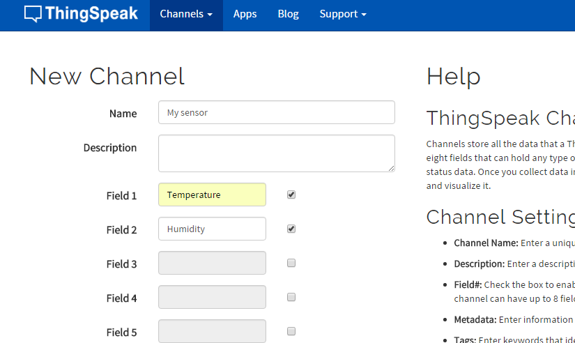
Now click on the "New Channel" (second image above). Give it a name and select two fields. If you want you can fill more info about your channel, e.g. Latitude and Longitude of your sensor. If you want to share sensor info with your friends (and more..) click on the "Make Public?" check box option. Finally click on the "Save Channel" button.
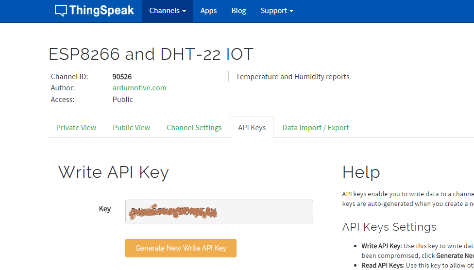
Click on your new channel and select the API keys tab (third image above). Copy your "Write API Key" , you will need it in the next step.
The Code


Here's the code, embedded using Codebender!
Before you proceed:
- Remove the RX and TX cables from the Arduino board
- Add your information in the code below by pressing the "Edit" button:
- #define SSID "name" // "SSID-WiFiname"
- #define PASS "password" // "password"
- String msg = "GET /update?key=YOUR_WRITE_KEY"; //change it with your key...
Try downloading the Codebender plugin and clicking on the "Run on Arduino" button to program your Arduino board with this sketch. And that's it, you've programmed your Arduino board directly from your browser!
Now you can re-connect the RX and TX cables. Now check your ThingSpeak channel to see the first sensor's info!
The "delay(3600000);" will send data to your ThingSpeak channel every one hour. It's not the best way for counting, but it's working fine ;).
How to find time in milliseconds:
1 minute has 60000ms, so for example: 15 minutes have 60000x15=900000ms
Data Logger


You can see my channel here: https://thingspeak.com/channels/90526
Check it again in one hour!
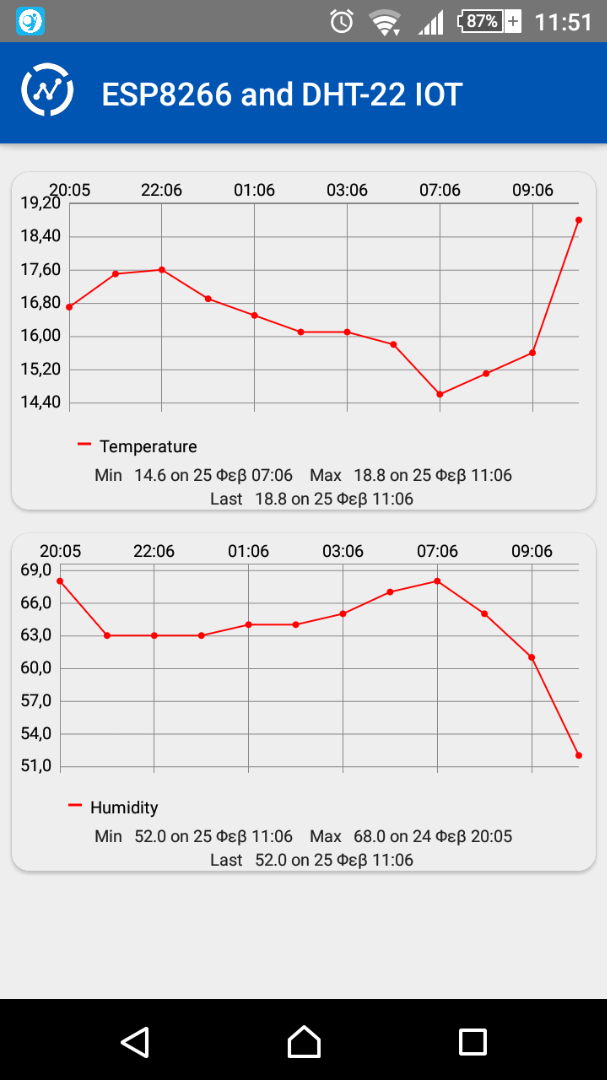
You can also download the "ThingView" application to your android device!
What Next?


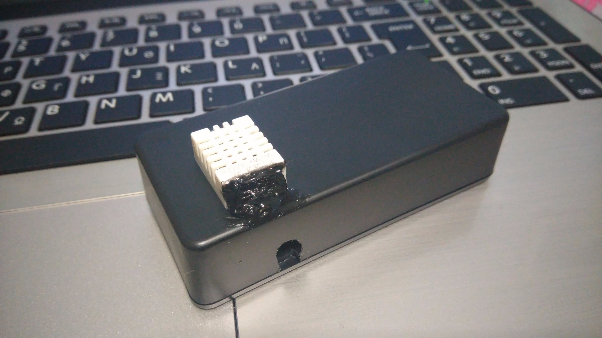
You can make your own Arduino-based circuit and put it in a small box, just make sure that the sensor will be out of it.
I made mine and placed it on the wall outside of my house, you can check my temperature and humidity values here!
Future updates:
- add a real clock circuit to control the time of data sending with accuracy
- add a rechargeable battery and one small solar panel
- add more charts for monthly and yearly average values
Well Done!

You have successfully completed this guide and now you have your own Arduino IOT device up and running!
For more Arduino tutorials and cool projects you can visit our web page: www.ardumotive.com
I hope you liked this, let me know in the comments!