Arduino Interactive Simon-Says
by Ayan Adhyapak in Circuits > Arduino
186 Views, 1 Favorites, 0 Comments
Arduino Interactive Simon-Says

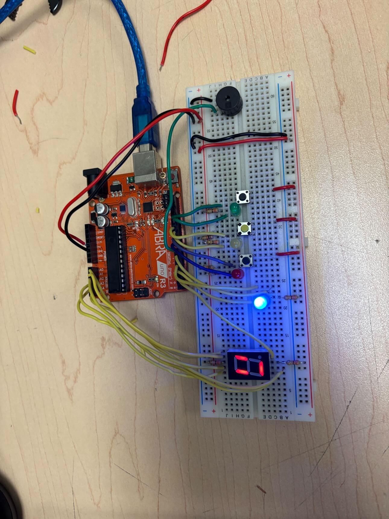
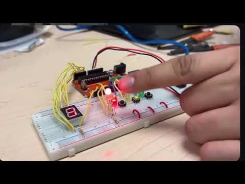
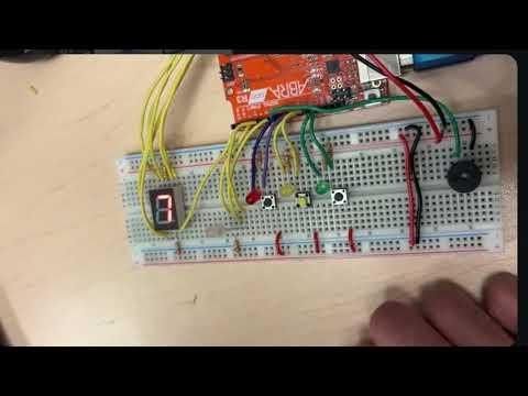
I wanted to make Arduino projects that was functional, interactive, and a game. This project is much more than simply blinking lights and 7 segments counting upwards, it's about handling multiple conditions and remembering what was being done, multiplexing displays, and designing a responsive user experience. My objective was to create a Memory/Simon-Says game that will enable the user to remember random series. It assesses cognitive retention and reaction time with visual (LED), auditory (Buzzer) and numeric (7-Segment) feedback.


Supplies
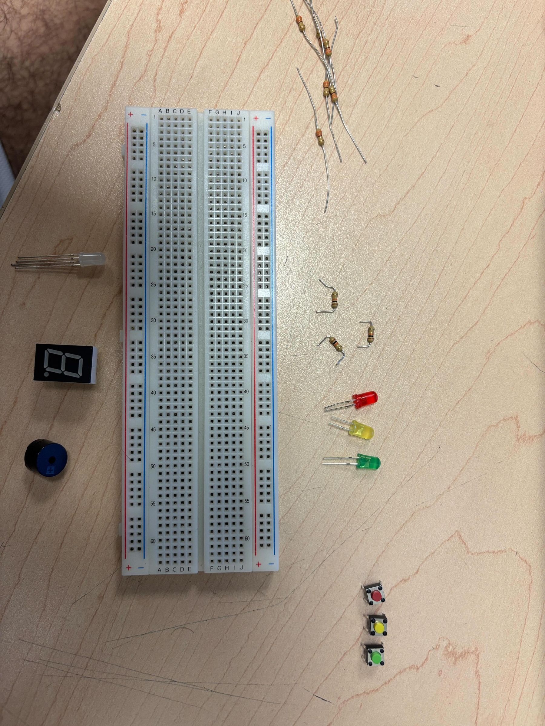
Below are the components required to build this project.
- Arduino Uno R3 (1)
- Common Anode 7-Segment Display (1)
- 5mm LEDs: Red (1), Yellow (1), Green (1)
- Tactile Pushbuttons (3)
- Piezo Buzzer (1)
- RGB LED, Common Anode (1)
- 330Ω Resistors (7)
- Breadboard
Breadboard Layout Planning (Before Wiring)
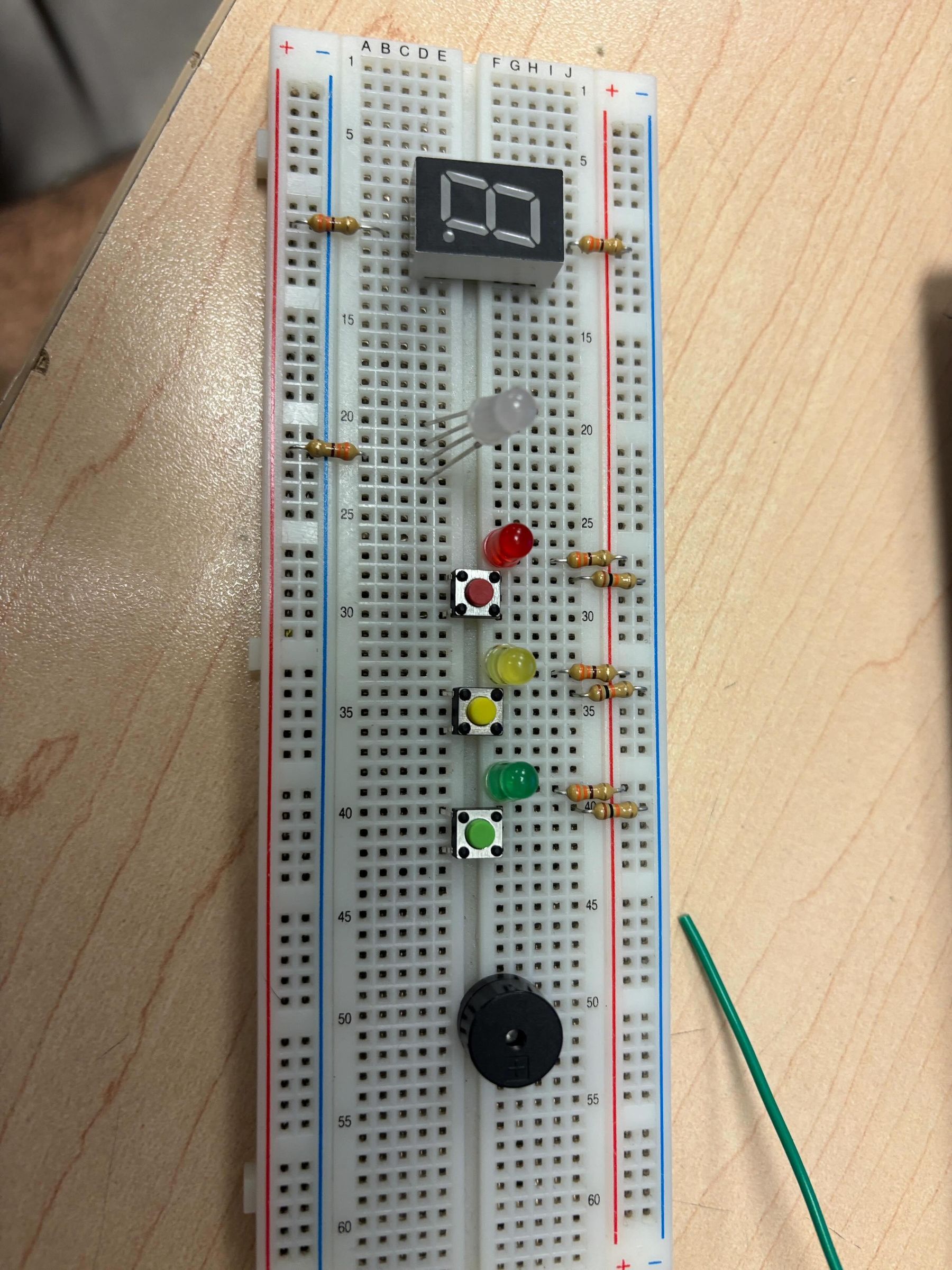
This image shows the breadboard before any components or wires were added. At this stage, nothing was physically connected, but the purpose of this step was to plan how everything would be placed before starting the actual wiring process.
It made sense to use the top line for my 5V and the bottom line for my ground as this provides all components with their power source. Given that I am using so many components, for instance; three pushbuttons, three single LEDs, an RGB LED, a buzzer, and a 7-segment display, it made sense to have a clean power layout in order not to clutter the wiring.
Following this I decided how I should arrange my parts depending on their use: I put the three pushbuttons together in close proximity to limit my input wiring, I put the three single LEDs together so that there would be no ambiguity of how each input would work and where each feedback indicator was, I kept the RGB LED slightly separate from the others so it stands out as the final game indicator and also placed the 7-segment display to ensure I could read my score easily.
Finally I decided where on the Arduino each pin would be designated and ensuring that all my inputs are separate from my outputs, setting the appropriate pins for the RGB LED and also deciding which pin would be connected to each number on the 7-segment display.
I decided it was important to create this plan before connecting any wires so that I wasn't just plugging wires into pins hoping they worked.
Circuit Theory and Logic
The circuit has 5 hardware systems, all sharing the same 5V and ground supply but each connected to their own Arduino pins.
The 3 buttons are inputs, each on their own digital pin with a pull-down resistor to prevent floating. The 3 single-color LEDs are outputs, each wired through a 330Ω resistor to its own pin so they can be controlled individually. The RGB LED is also an output but uses 3 separate pins; one per color channel, allowing color mixing through PWM. The buzzer is on a single output pin and shares the same ground.
The 7-segment display uses multiple digital input pins as the display is wired to an individual pin per segment. All segments use the same connection to the 5V power supply as it is a common anode display. It works by turning on individual segments on the display according to which is required to produce a particular number, it is therefore controlled by a look up table in the program as all the segments cannot be turned on as a group by the Arduino.
Although each of the systems above is separated in hardware, each of them work together in the same system by sharing a ground and 5V supply. Each system is connected to the Arduino in a way which it can recognize that part of the system independently of others and react accordingly, the Arduino will read values from the inputs and produce an output as seen fit through each of the systems and they will appear to work as a complete system due to switching between input and output rapidly.
Wiring the Components
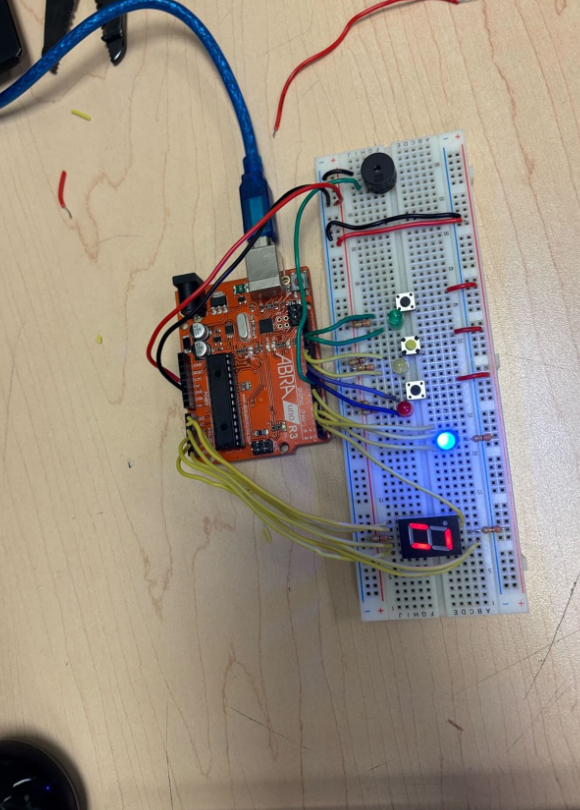
Wiring could now be started since all parts had been positioned. Each part was connected in stages instead of all at once so that there would be no mistakes. The power rail (top) was connected to the 5V of the Arduino and the ground rail (bottom) to its GND, so all components would receive power before any signal wires would be connected. The anode (longer leg) of each LED was connected to an output pin of the Arduino via a 330Ω resistor.
The shorter leg is a cathode and it is connected to ground. Each of the 3 buttons was connected to the same leg on the board with the other leg connected to ground via a resistor to keep the pin from floating. The common anode side of the RGB LED was connected to 5V, and each color leg (red, green, and blue) was connected to a separate PWM capable pin (pins 3, 6, and 4).
AnalogWrite() can control brightness and mix colors by using PWM pins. The buzzer was connected such that the positive terminal was connected to pin 7 and the negative terminal was connected to ground.
The 7-segment was the most complex segment to wire as it requires 7 individual segment pins and a common anode. The common anode was wired to the 5V supply and each 7 segment pin (a through g) was connected to a 330Ω resistor and then to an individual Arduino pin.
The analog pins A0–A5 were also used as digital output pins to accommodate the need for numerous pins to power the LEDs, buttons and buzzer, in addition to pin 2.After wiring up everything and programming the code, the RGB LED was illuminated with a blue color and the 7-segment was displaying the idle pattern, establishing that all connections were correct.
Tinkercad Schematic
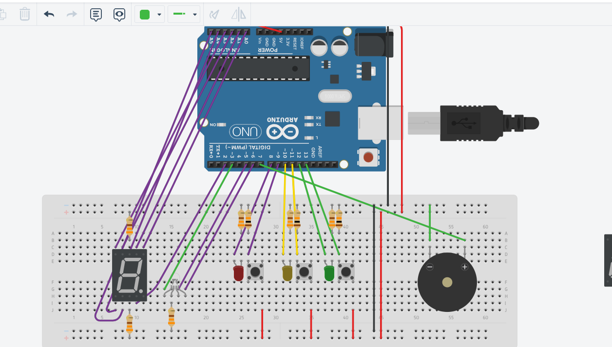
The Tinkercad diagram above shows the complete pin mapping for the project.
- The 7-segment display sits at the left of the breadboard with each segment wired to analog pins used as digital outputs
- The RGB LED uses PWM pins 3, 4, and 6 for color control
- Each LED/button pair shares the same row zone on the breadboard
- The buzzer sits at the far end connected to pin 7
- All components share the same 5V and GND rails running along the breadboard edges
The Code
The code is split into separate functions, each handling one part of the game. All pin numbers are declared at the top as variables so they only need to be changed in one place if anything is rewired.
The tones[] array stores three buzzer frequencies, one per button. The digits[11][7] array is a lookup table where each row stores which segments turn on to display a digit, so instead of writing a separate function for each number, one for loop handles it all.
setup() runs once, sets all pins as INPUT or OUTPUT, seeds the random number generator with millis(), then enters idle state — RGB blue, smiley on the display. loop() runs continuously, showing the idle screen until a button press is detected, then calls startGame().
The gamePattern[] array is filled with 10 random numbers (0–2) representing red, yellow, and green. showSequence() flashes each LED with its matching tone up to the current level. getPlayerInput() gives the player 5 seconds per button using millis(), wrong button or timeout returns false and ends the game. playCorrect(), playWrong(), and playWin() give RGB and buzzer feedback after each round. showScore() writes the current level to the display, inverting values with ! because the display is common anode.
Downloads
Code Reference and Differences
This project was built with reference to an existing Arduino memory game as a starting point for understanding how a Simon Says game could be structured. The code was rewritten with a different approach throughout. Below are the main differences.
The original code has a separate function for every digit; one(), two(), three() and so on, each manually writing HIGH or LOW to every segment. This is repetitive and means changing one digit requires editing an entire function.
My version replaces all of this with a single digits[11][7] 2D array. Each row stores the segment pattern for one digit. To show a number, one for loop reads the right row and writes it:
This is cleaner, shorter, and easier to update.
3 buttons and LEDs instead of 4
The original uses 4 colored buttons and LEDs. My version uses 3, which changes the pin layout, the tones array, and the random number range. gamePattern[] stores values 0–2 and random(0, 3) is used to generate them.
Full RGB color feedback
The original only partially implements the RGB LED, one channel is commented out and only red and blue are used. My version uses all three channels through PWM pins to produce four distinct colors: blue for idle, green for correct, red for wrong, and yellow for win. Because the RGB is common anode, the values are inverted:
Button release detection and debouncing
The original reads a button press and immediately moves on with no check for whether the button is still being held. My version adds waitForButtonRelease() which holds the program until the player physically lets go before accepting the next input. A double-check with a 50ms delay is also added in loop() to filter out false triggers from electrical noise.
10 rounds instead of 5
The original ends after 5 rounds. My version runs 10, which required a gamePattern[] array of size 10 and a win condition check at currentLevel == 10.
Cleaner game flow with boolean return
The original's win/lose logic is spread across the main loop. My version wraps input checking inside getPlayerInput() which returns either true or false. The result is handled in one place inside playGame(), making the logic easier to read and follow.
Downloads
Final Product — How to Play