Arduino LED Blink Project – First Step Into Arduino Programming
by ElectronicsBD in Circuits > Arduino
62 Views, 0 Favorites, 0 Comments
Arduino LED Blink Project – First Step Into Arduino Programming

Arduino LED Blink Project - The Perfect First Arduino Project
If you're new to Arduino, the LED Blink project is the best place to start. Although it's simple, this project teaches the basic concepts of Arduino programming, digital outputs, circuit wiring, and uploading code.
In this tutorial, you'll learn how to connect an LED to an Arduino Uno, write a simple program, and make the LED blink every second.
After completing this project, you'll have the knowledge needed to move on to more advanced Arduino projects involving sensors, displays, motors, and IoT devices.
Supplies
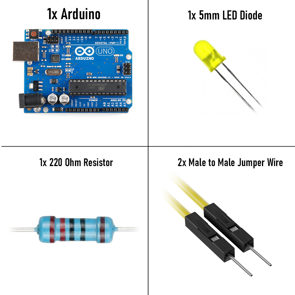
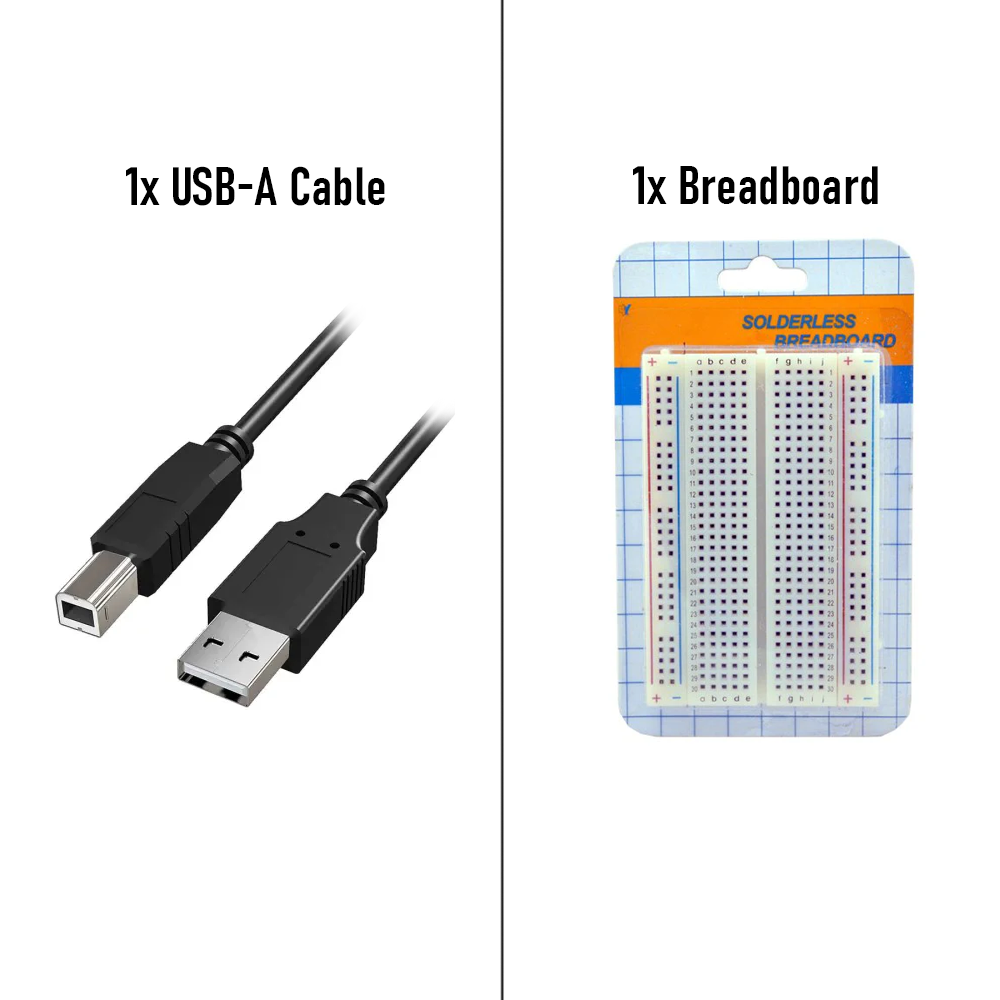
1 × Arduino Uno (or Nano, Mega, ESP32 with minor code changes)
1 × 220Ω resistor (330Ω also works)
Computer with Arduino IDE installed
If You Live in Bangladesh, You might consider buying products directly from our store.
Product links are given below.
Arduino Uno - https://www.electronics.com.bd/arduino-uno-r3-board
Arduino Nano - https://www.electronics.com.bd/arduino-nano-atmega328p-ch340
Arduino Uno (SMD) - https://www.electronics.com.bd/arduino-uno-r3
5mm LED Diode (RED) - https://www.electronics.com.bd/led-basic-red-5mm
5mm LED Diode (Yellow) - https://www.electronics.com.bd/led-basic-yellow-5mm
5mm LED Diode (Blue) - https://www.electronics.com.bd/led-basic-blue-5mm
5mm LED Diode (Green) - https://www.electronics.com.bd/led-basic-green-5mm
Breadboard Half - https://www.electronics.com.bd/led-basic-green-5mm
USB 2.0 Male USB A to Male USB B Cable - https://www.electronics.com.bd/usb-2-0-male-usb-a-to-male-usb-b-cable-for-arduino-uno-1-5-meter
How It Works
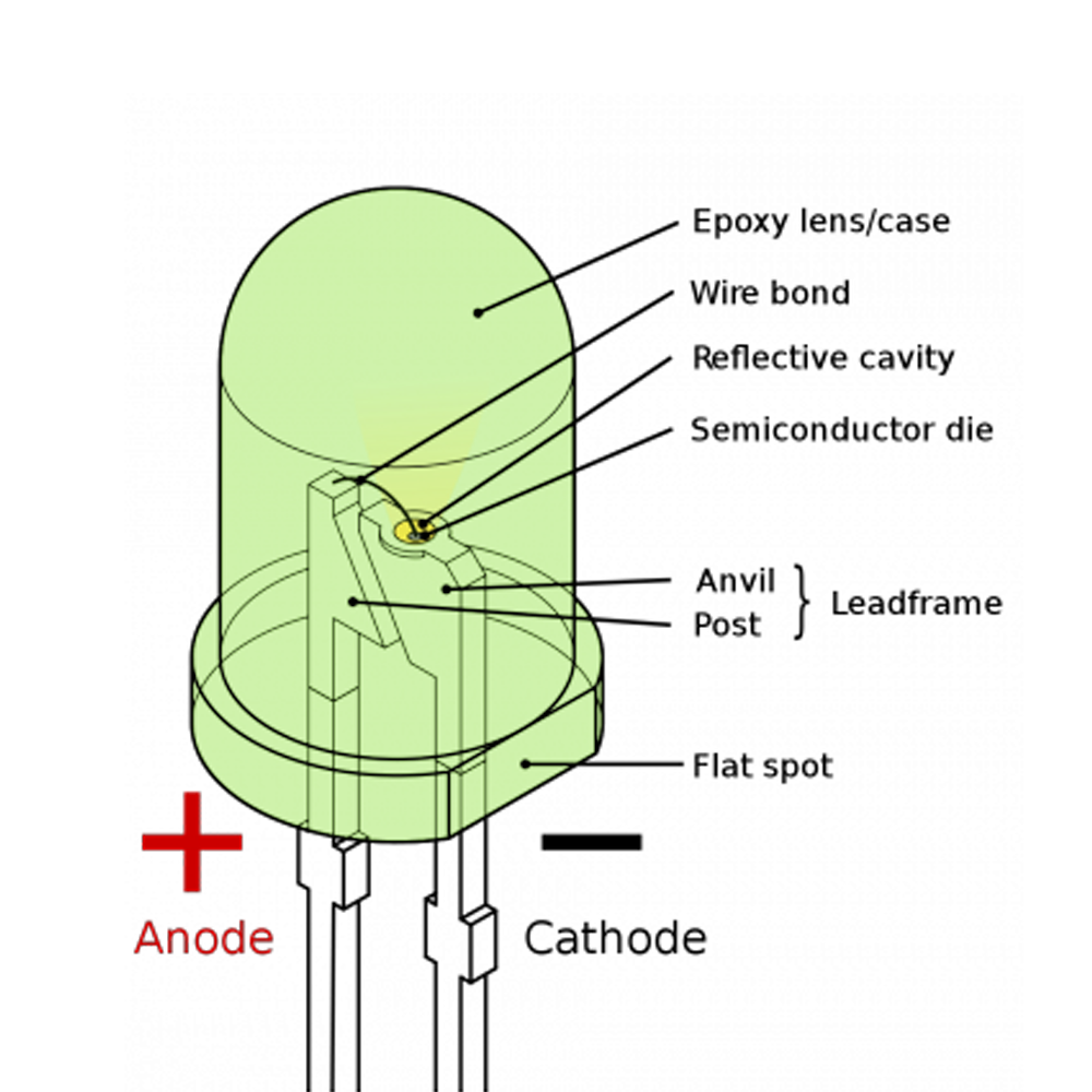
Step 1: Understanding the Project
An LED (Light Emitting Diode) lights up whenever electrical current flows through it.
The Arduino controls the LED by changing the voltage of one of its digital output pins.
- HIGH = 5V Output = LED ON
- LOW = 0V Output = LED OFF
By repeatedly switching between HIGH and LOW with a delay, the LED continuously blinks.
Circuit Connection
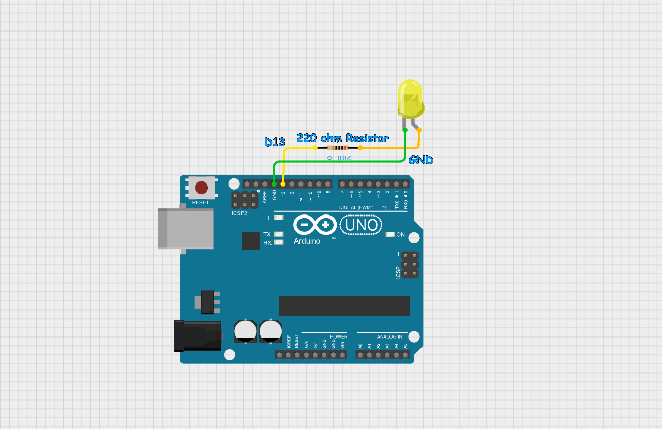
Step 2: Circuit Connection
- Arduino D13 → 220Ω Resistor
- 220Ω Resistor → LED Positive (Anode)
- LED Negative (Cathode) → Arduino GND
Tip: The longer leg of the LED is the positive terminal (Anode).
Install Arduino IDE
Step 3: Install Arduino IDE
- Download the Arduino IDE from the official Arduino website.
- Install the software.
- Connect the Arduino using a USB cable.
- Select the correct Board from the Tools → Board menu.
- Select the correct COM Port from the Tools → Port menu.
Arduino Code
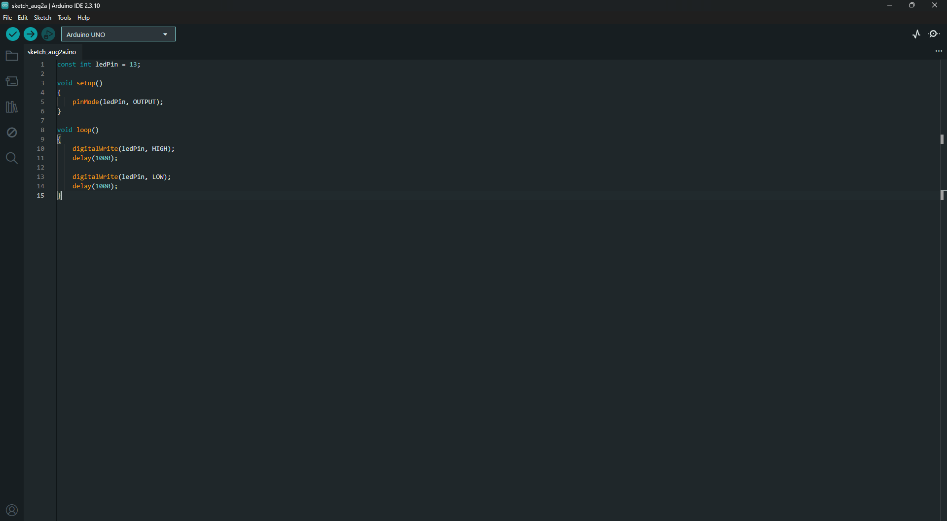
Step 4: Upload the Code
Copy the following code into the Arduino IDE.
Click the Upload button. After uploading, the LED should begin blinking every second.
Code Explanation
Step 5: Understanding the Code
Define the LED Pin
This line tells the Arduino which digital pin is connected to the LED.
Setup Function
The setup() function runs only once after the Arduino powers on. Here, pin 13 is configured as an output.
Loop Function
The loop() function repeats forever while the Arduino is powered.
Turn LED ON
This supplies 5V to the LED, turning it on.
Delay
The Arduino waits for 1000 milliseconds (1 second).
Turn LED OFF
This removes the voltage from the LED, turning it off.
Experiment
Step 6: Try Different Blink Speeds
You can change the blinking speed by modifying the delay values.
Fast Blink
delay(200);
Slow Blink
delay(2000);
Custom Blink Pattern
digitalWrite(ledPin, HIGH);
delay(100);

digitalWrite(ledPin, LOW);
delay(900);
Experiment with different values to create your own blinking patterns.