Arduino Line Following Bot
Welcome to my Instructible on a line follower bot controlled by an Arduino and a motor module!
This project demonstrates how to build a simple line following robot using an Arduino Uno, two FM90 DC motors, an L298N motor driver, and two TCRT5000 infrared sensors. When finished, the robot will be able to autonomously follow a strip of black electrical tape by detecting the contrast between the dark tape and the light-coloured floor.
The robot uses differential steering, meaning it changes direction by varying the movement of its left and right wheels. The design is built on an aluminum chassis with two powered front wheels and a freely rotating rear caster wheel.
This project introduces concepts such as sensor feedback, motor control, wiring troubleshooting, and mechanical design.
Supplies
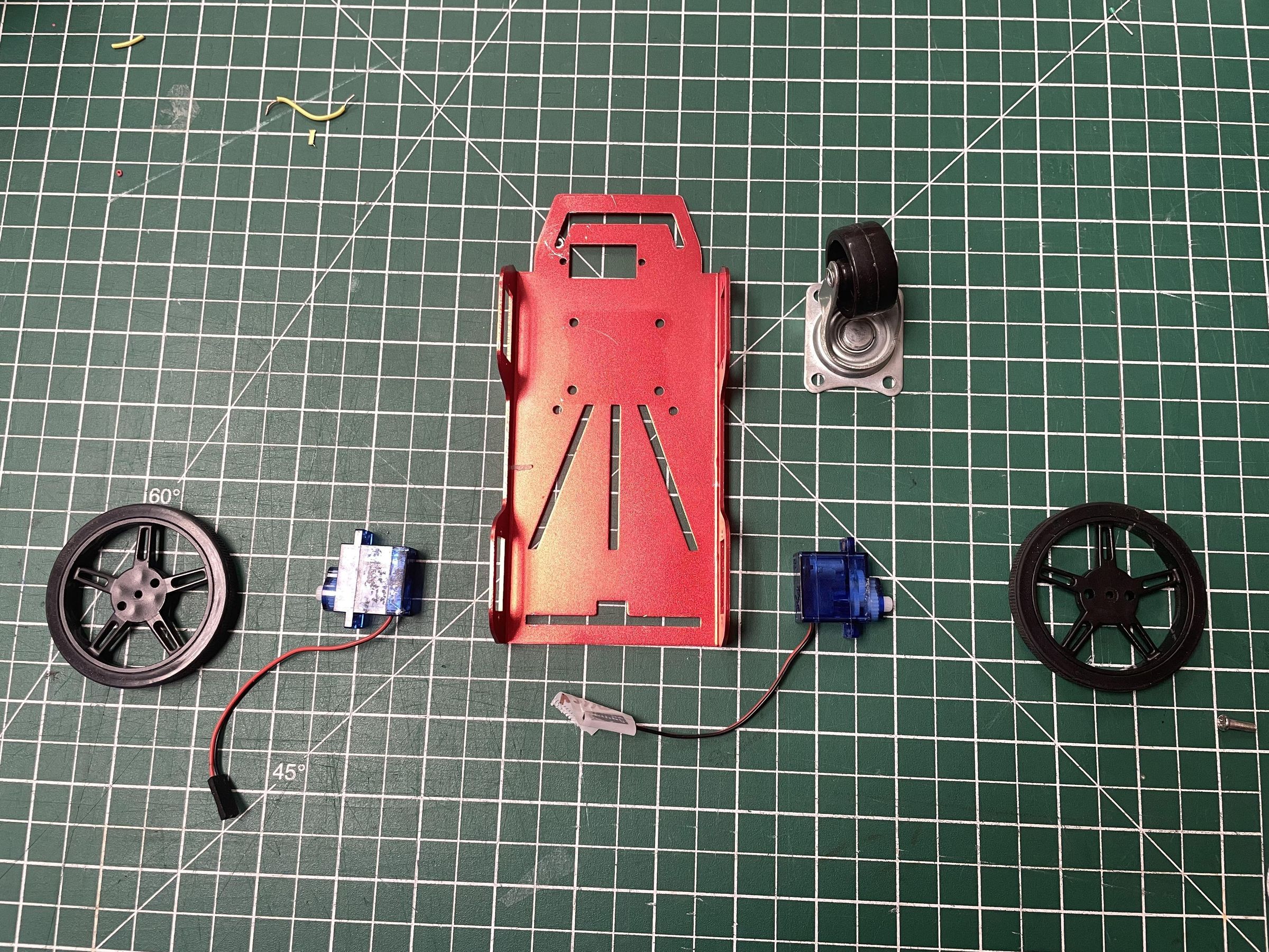
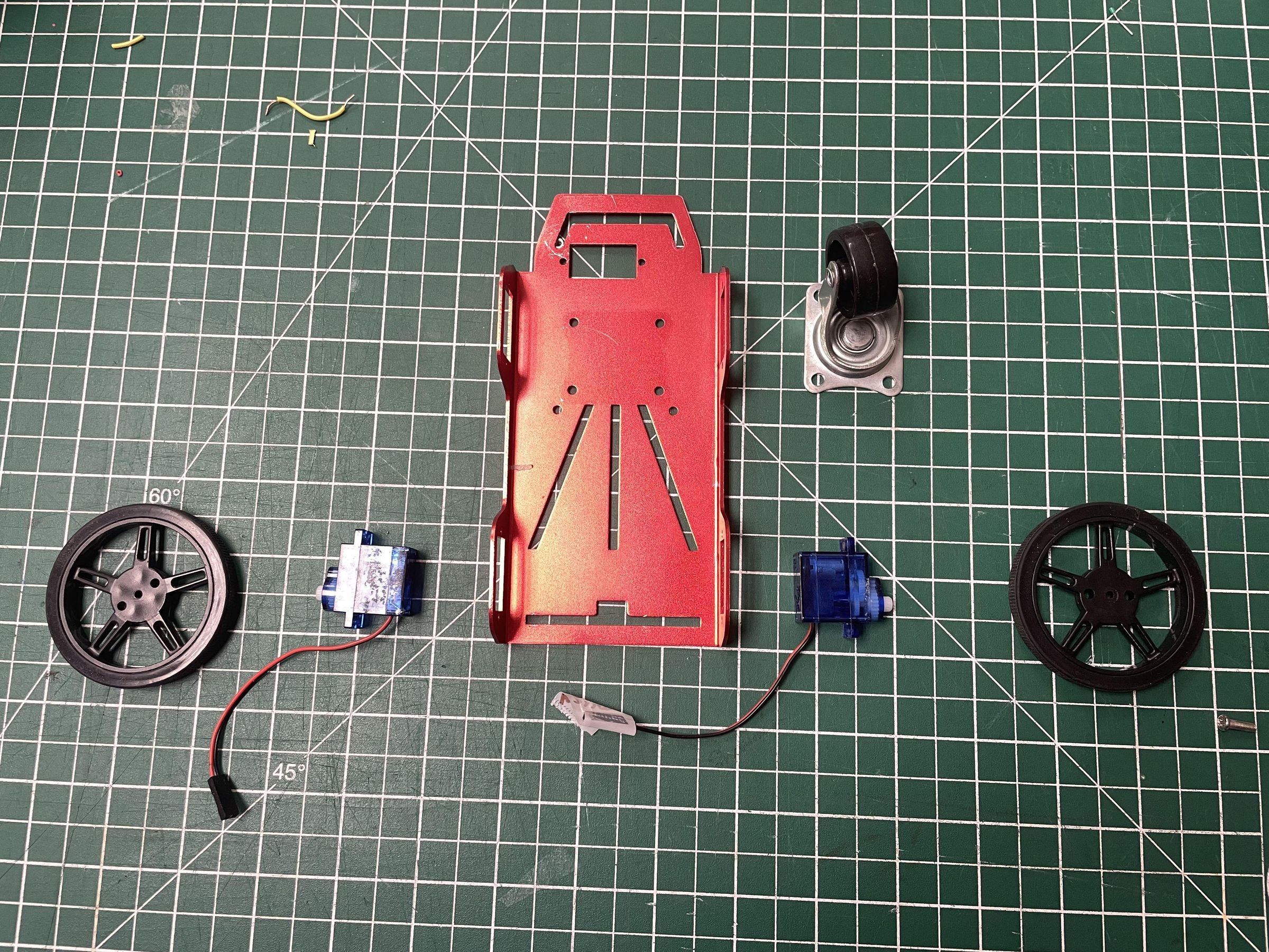
For this project, you'll need:
Electronics:
- Arduino Uno
- L298N Motor Driver Module
- 2 × TCRT5000 Infrared Reflective Sensors
- 2 × FM90 DC Motors in Micro Servo Body
- 12 V Rechargeable Battery
- Mini Breadboard (or regular)
- Jumper Wires (male to female)
- Male to male wires (if needed)
- Female to female wires (if needed)
- Regular wires
- Electrical Tape
Mechanical Components:
- Aluminum Robot Chassis
- 2 × Wheels
- Rear Caster Wheel
- Spacers/Standoffs
- Washers
- Mounting Screws and Nuts
- Counterweight (if needed)
Tools:
- Phillips Screwdriver
- Flathead Screwdriver
- Wire Cutters
- Computer with Arduino IDE
- USB Cable
Inspect the Chassis
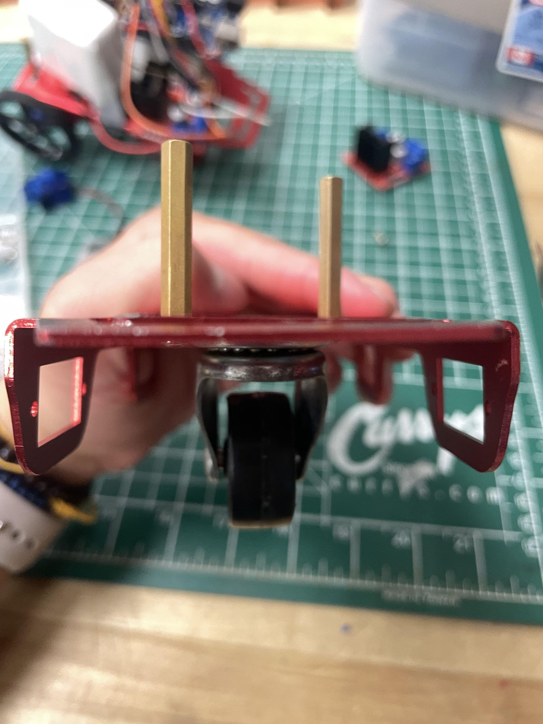
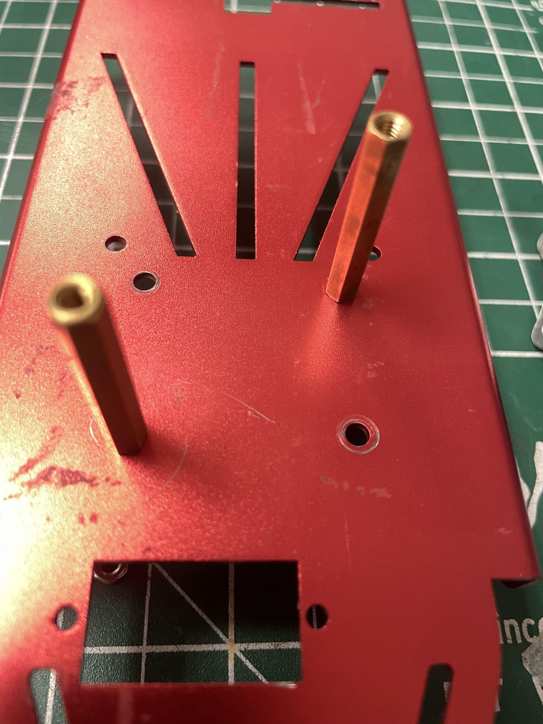
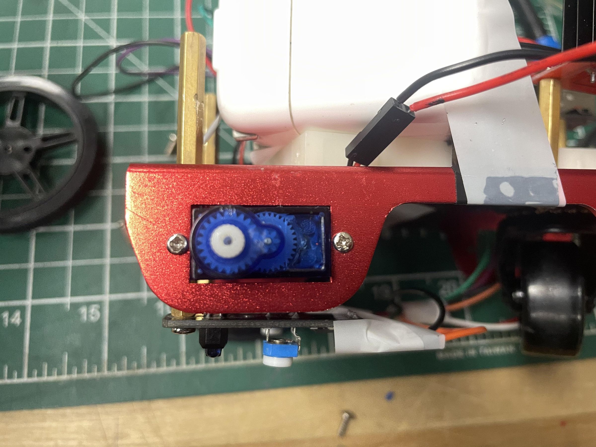
The robot is built on an aluminum chassis that includes pre-drilled mounting holes and motor slots. These features simplify assembly as no drilling, cutting, or 3D printing is required.
Before installing components, be sure to identify:
- Motor mounting slots
- Electronics mounting holes
- Battery placement area
- Rear caster wheel mounting location
Because the mounting holes are predetermined, component placement options are limited. This became an important factor later when balancing the robot.
Install the Motors and Wheels
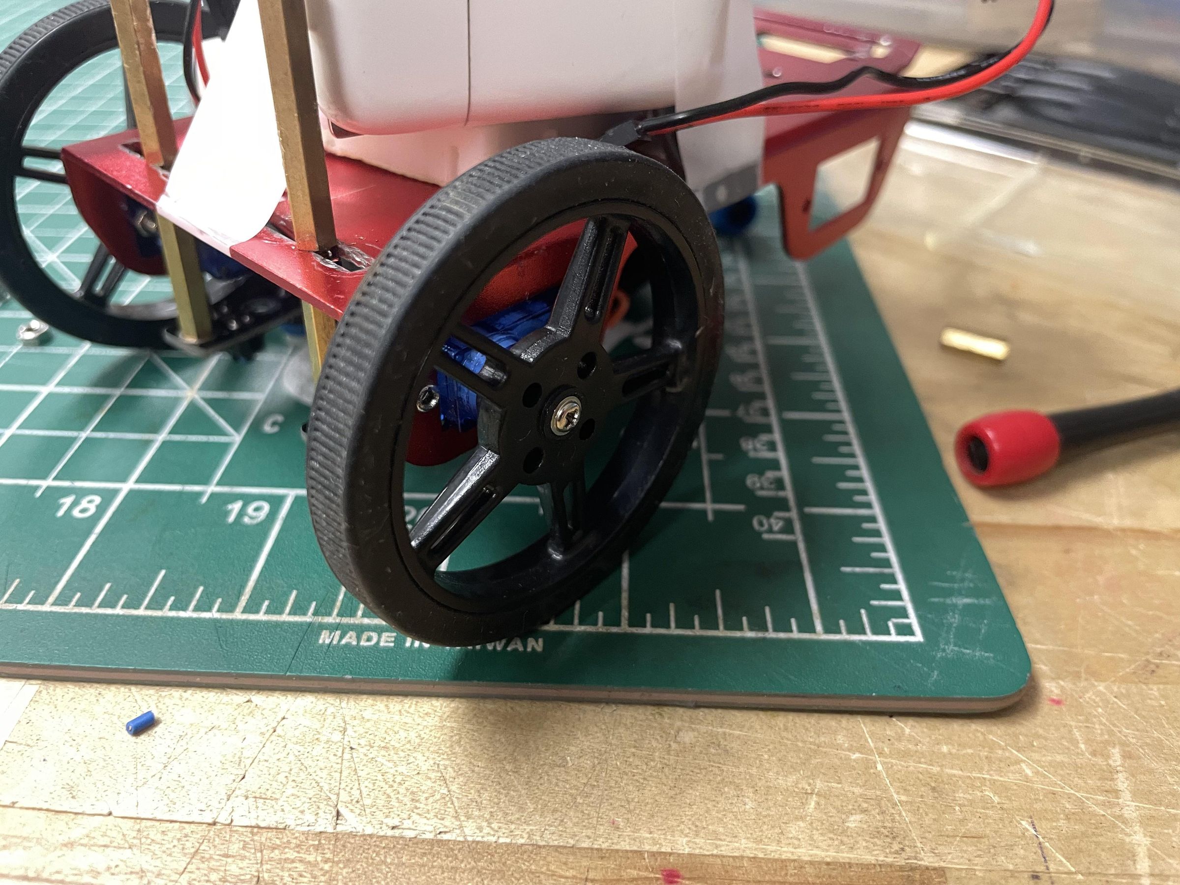
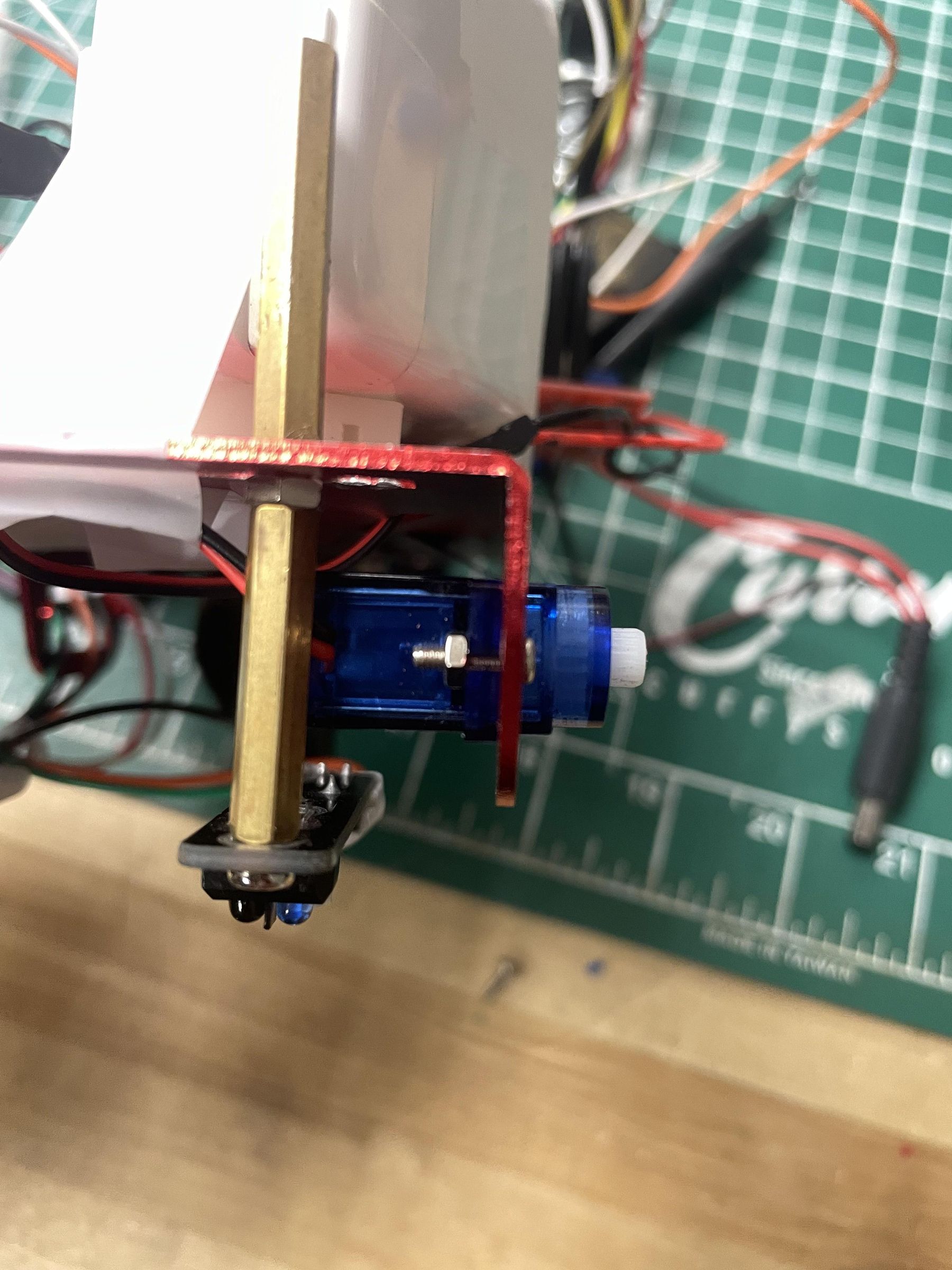
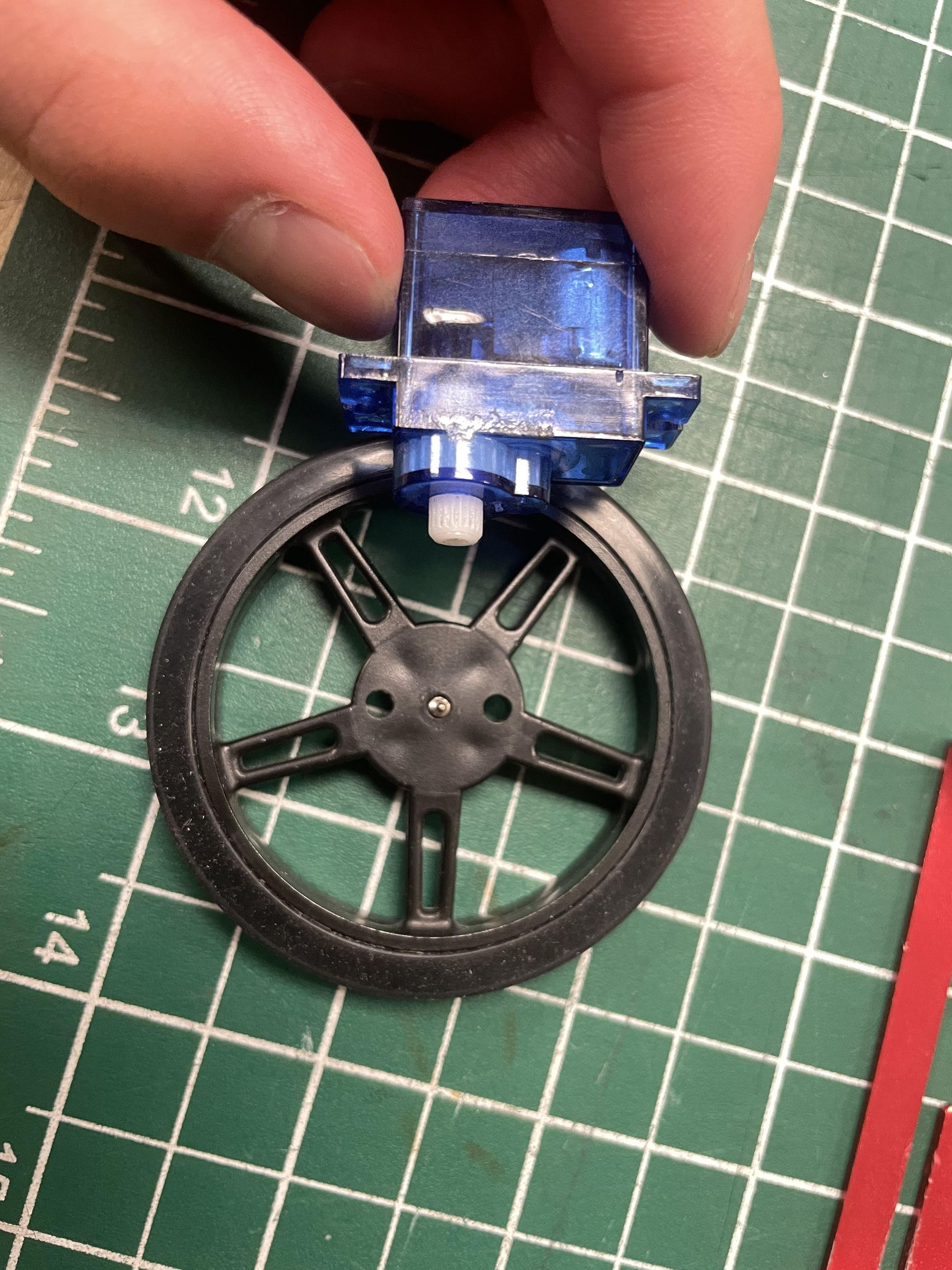
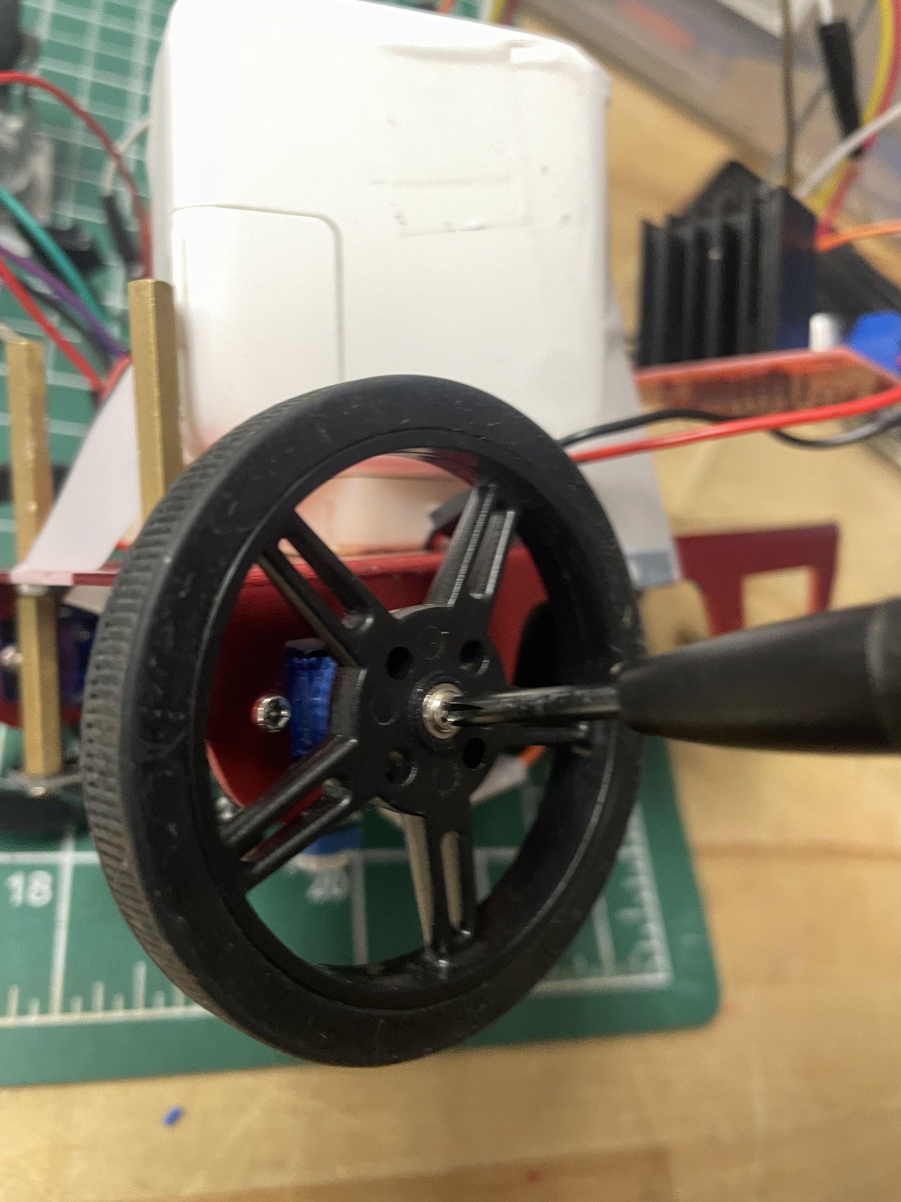
The chassis contains dedicated slots for the FM90 DC motors.
Procedure
- Remove wheels from both motors by unscrewing.
- Insert the left motor into the left motor slot.
- Insert the right motor into the right motor slot.
- Align the mounting holes.
- Secure the motors using screws.
Important Tip
Test each motor before installation.
Connect each motor (with wheel) briefly to a power source and ground, and verify that:
- It spins smoothly.
- There is no excessive noise.
- It does not stall unexpectedly.
A faulty motor can make troubleshooting extremely difficult later. Additionally, the motor should spin regardless of whether you connect power to the negative or positive, as motors can spin forward and backward.
Attach the Wheels
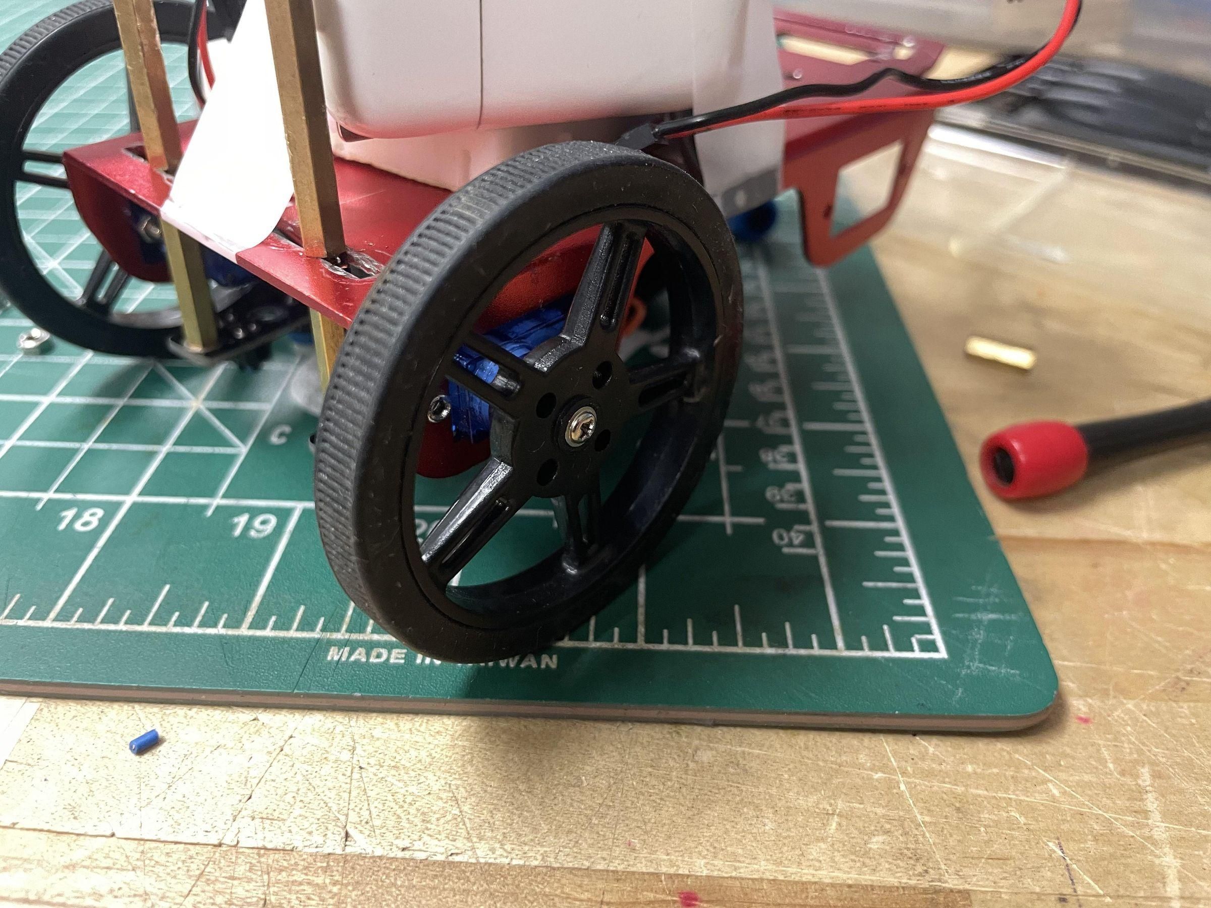
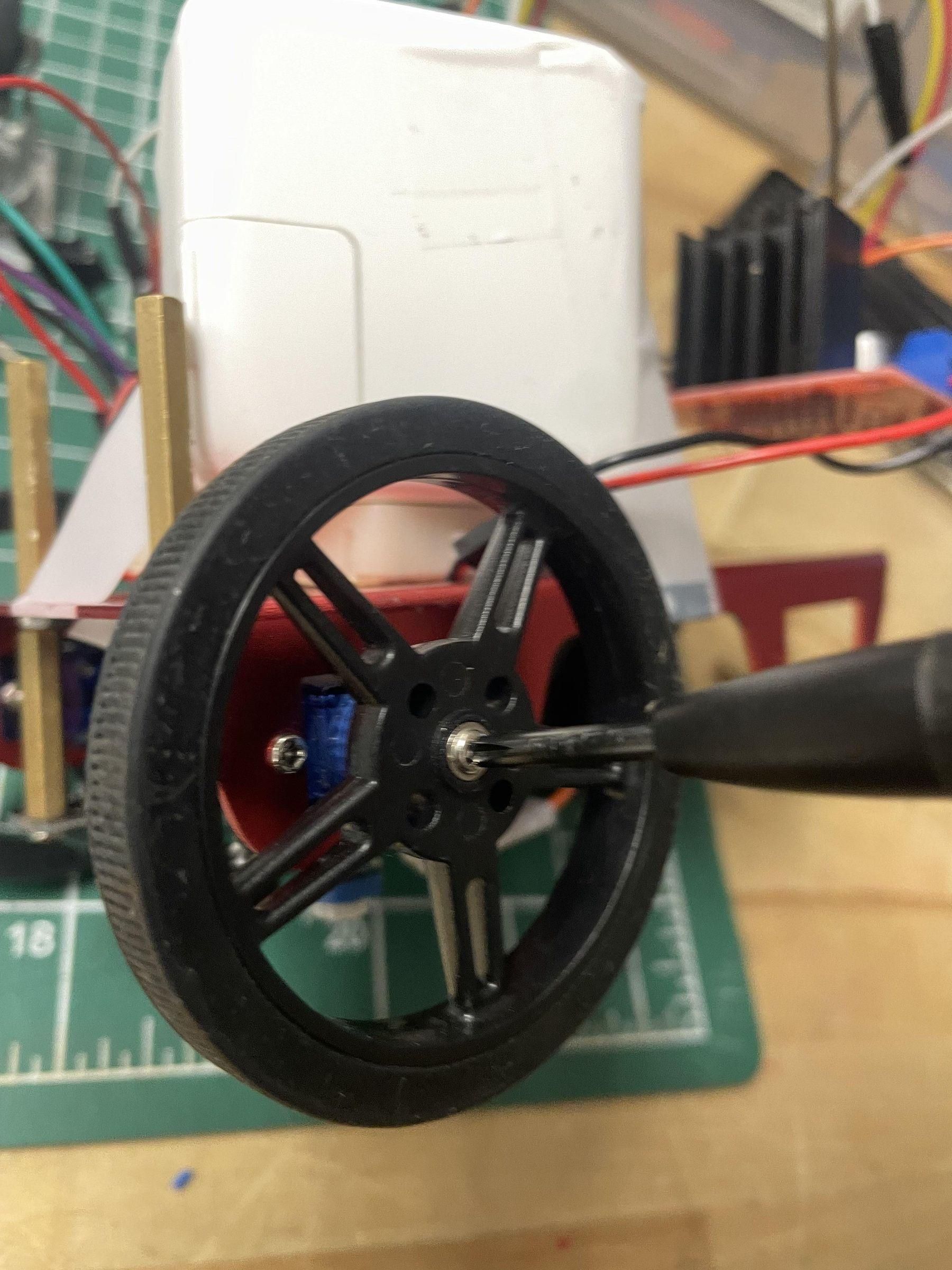
Remember the last step where you unscrewed the wheels? You can reconnect them in this step now that the motors are in place.
Attach one wheel to each motor shaft and screw them on using the Phillips screwdriver.
Ensure both wheels are fully seated, rotate freely, and have little to no wobble.
Install Rear Caster Wheel
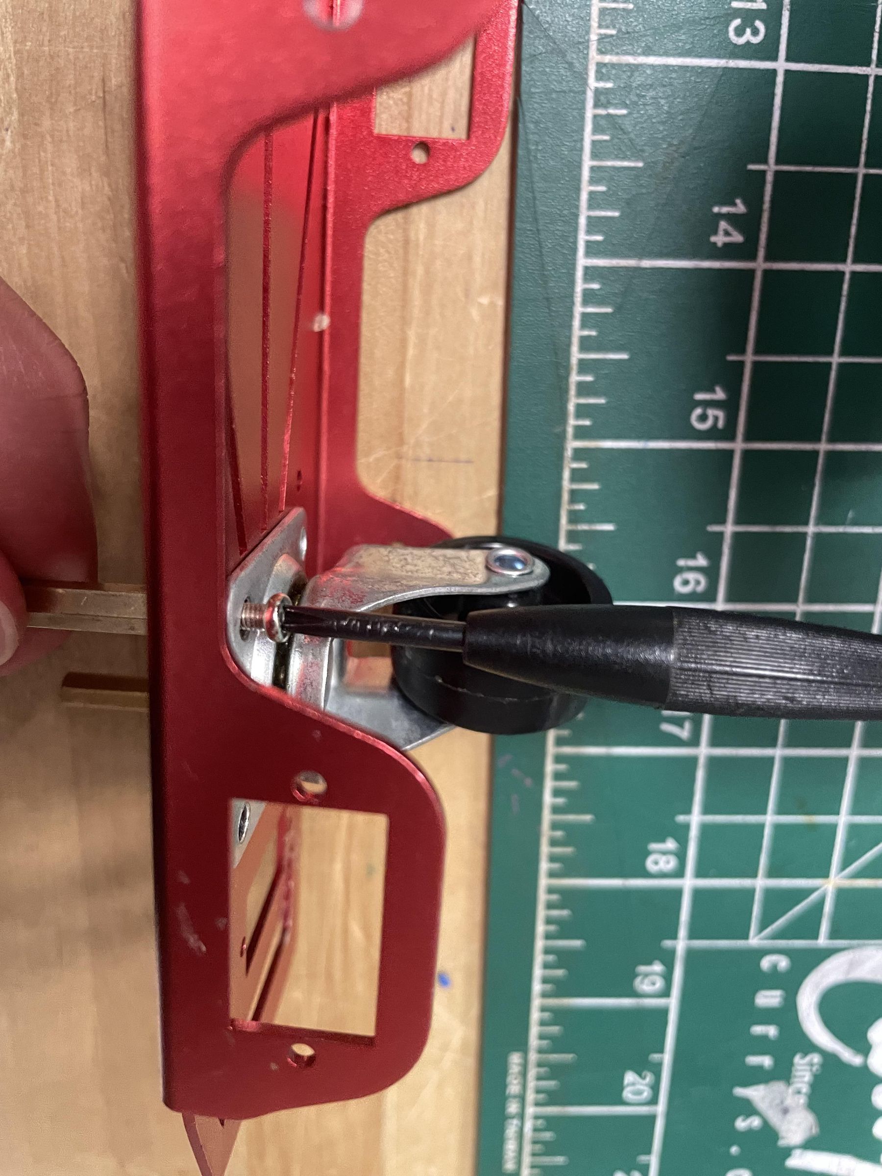
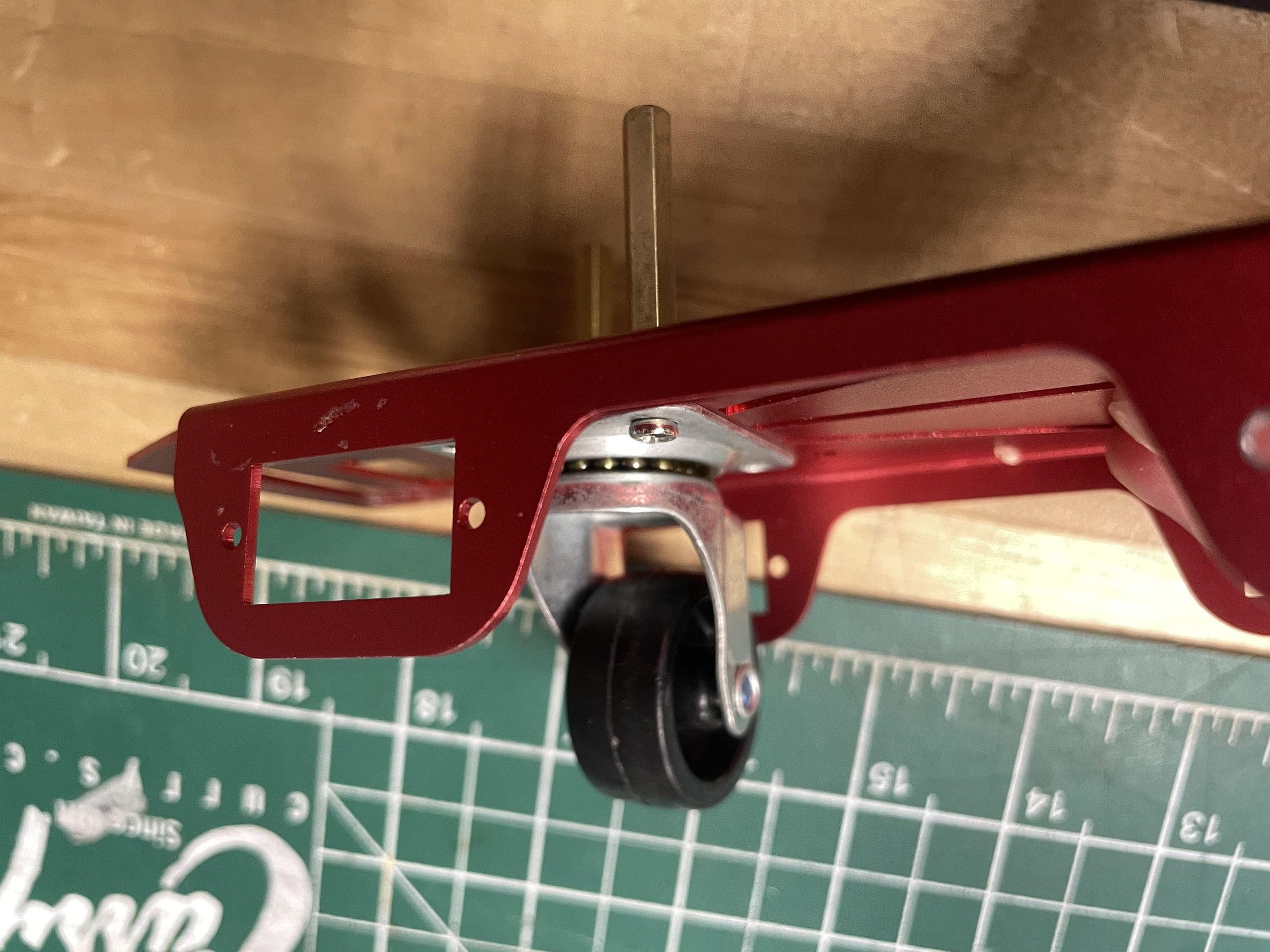
A caster wheel was mounted at the rear of the chassis, and unlike drive wheels, the caster wheel is not powered. It pivots freely in any direction and provides support while allowing the robot to turn smoothly.
Secure the caster wheel by positioning it at the appropriate holes and using spacers to screw them in. Simply place the spacer above the hole on the chassis and screw it in from the bottom.
Mount the Arduino Uno
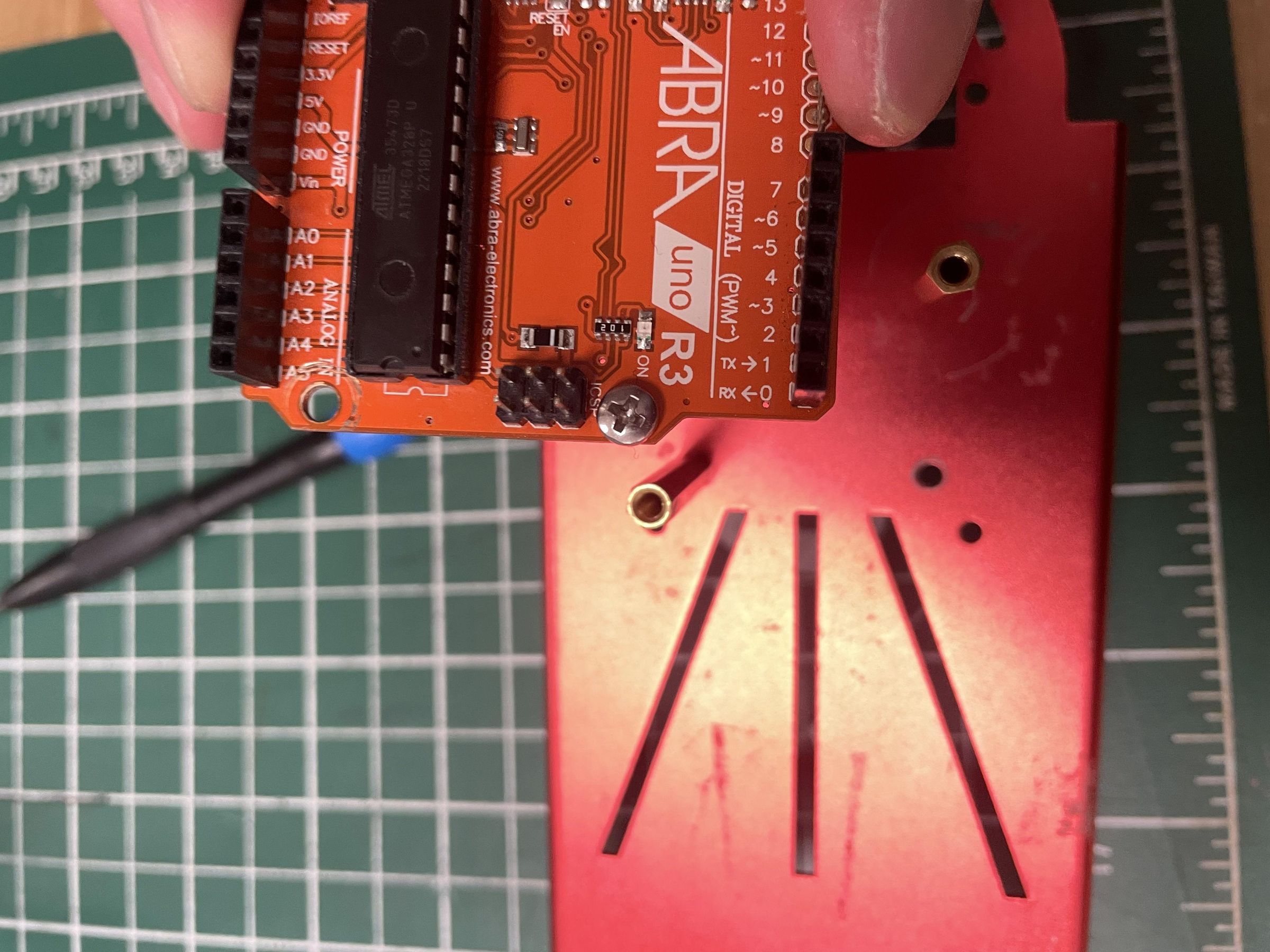
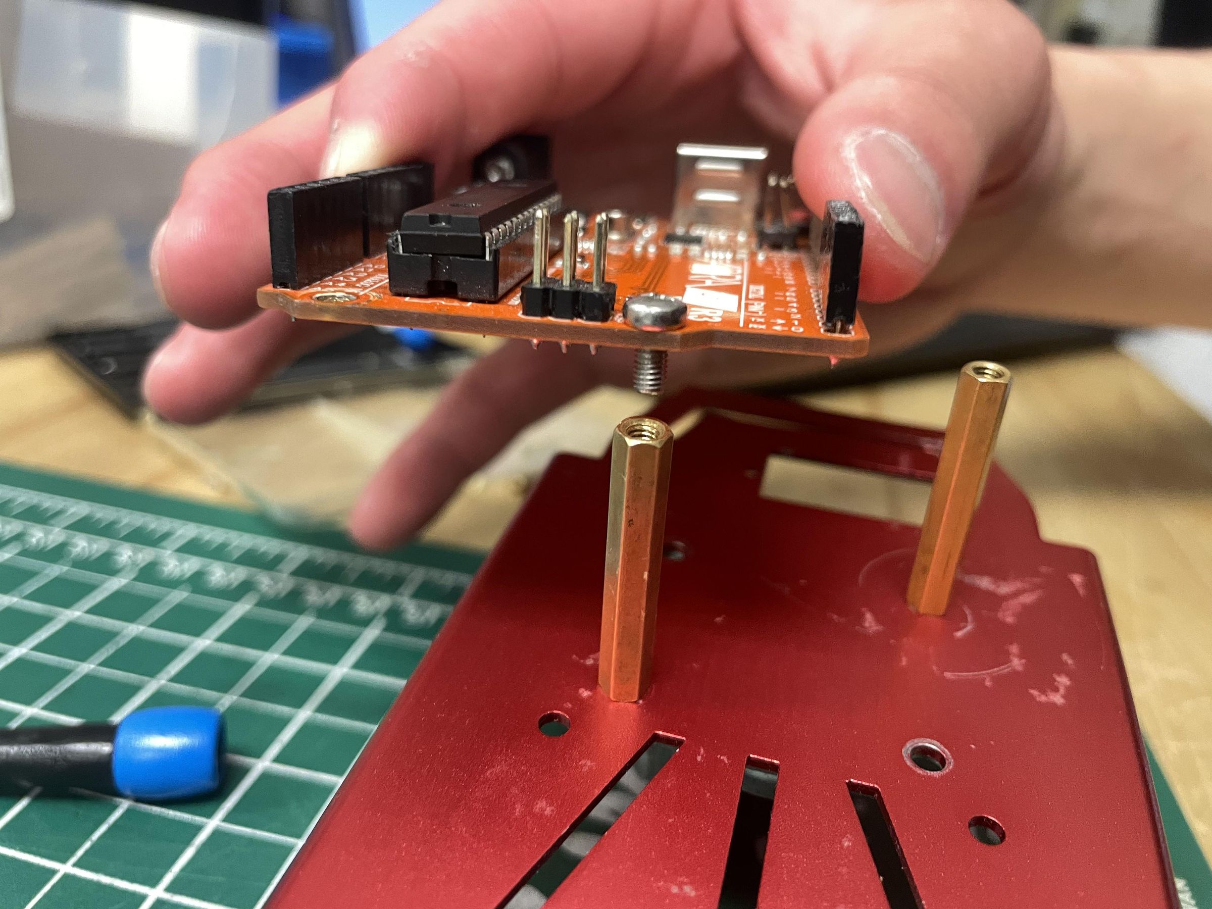
The Arduino Uno serves as the robot's controller.
The Arduino was mounted using spacers and screws attached to the chassis mounting holes.
To mount it, position one of the Arduino's corner screw holes directly above a precut hole on the chassis. Place a spacer in between these two holes and screw on both ends.
The spacers elevate the Arduino above the chassis and prevent electrical shorts.
It's important to remember that because the chassis contained fixed mounting locations, the Arduino could not be placed exactly where desired.
Mount the L298N Motor Driver
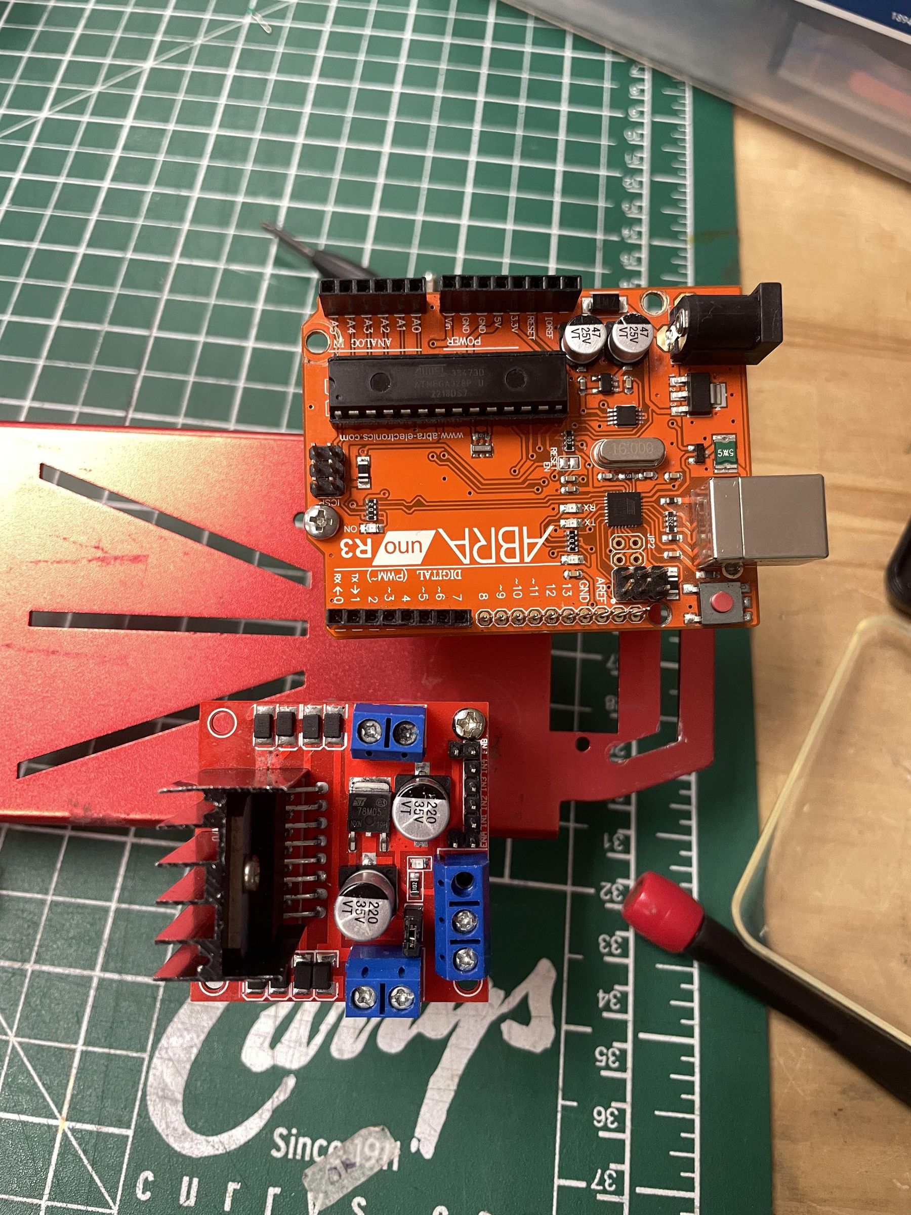
The L298N motor driver controls the motors based on commands from the Arduino.
Like the Arduino, the motor driver was mounted using spacers and screws, and mounting it is the same as mounting the Arduino: Place a screw hole above a chassis hole, insert a spacer in between the two holes, and screw in on both ends.
The available mounting holes forced the module into a less-than-ideal position, which contributed to uneven weight distribution.
Tip: Now that you've installed both the L298N and Arduino, try to pivot and adjust their position so that the weight is evenly distributed across the chassis so that you won't have to deal with any issues regarding uneven wheel traction later on. Once you've found a position you like, fasten the screws and test to make sure the Arduino and L298N don't wiggle.
Install the Breadboard
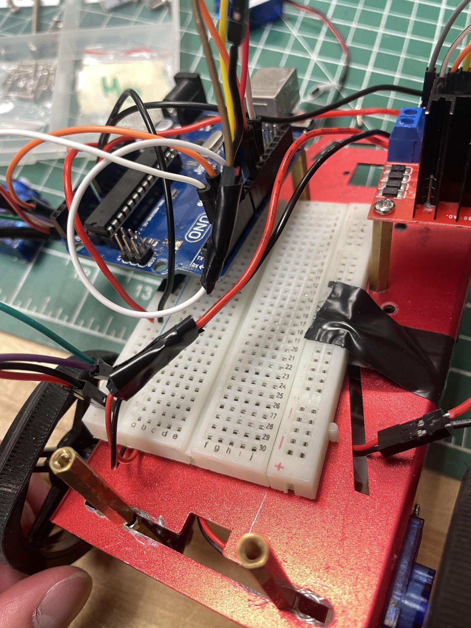
A mini breadboard was attached directly to the chassis using tape, although you can use a full-size breadboard as well. However, a full-size breadboard will make it harder to fit all components on the chassis.
To secure the breadboard onto the chassis, choose an appropriate location that isn't already used and tape the breadboard to that location.
The breadboard will be your hub for most power distribution and sensor connections.
Ensure that the breadboard is firmly attached before driving the robot.
Mount the Infrared Sensors
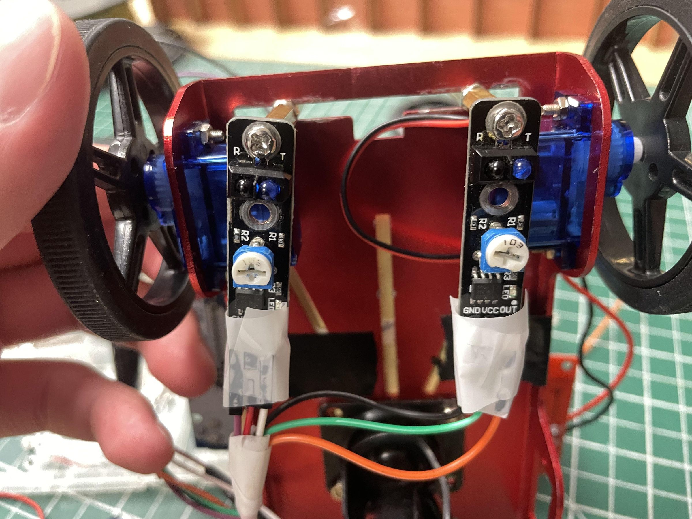
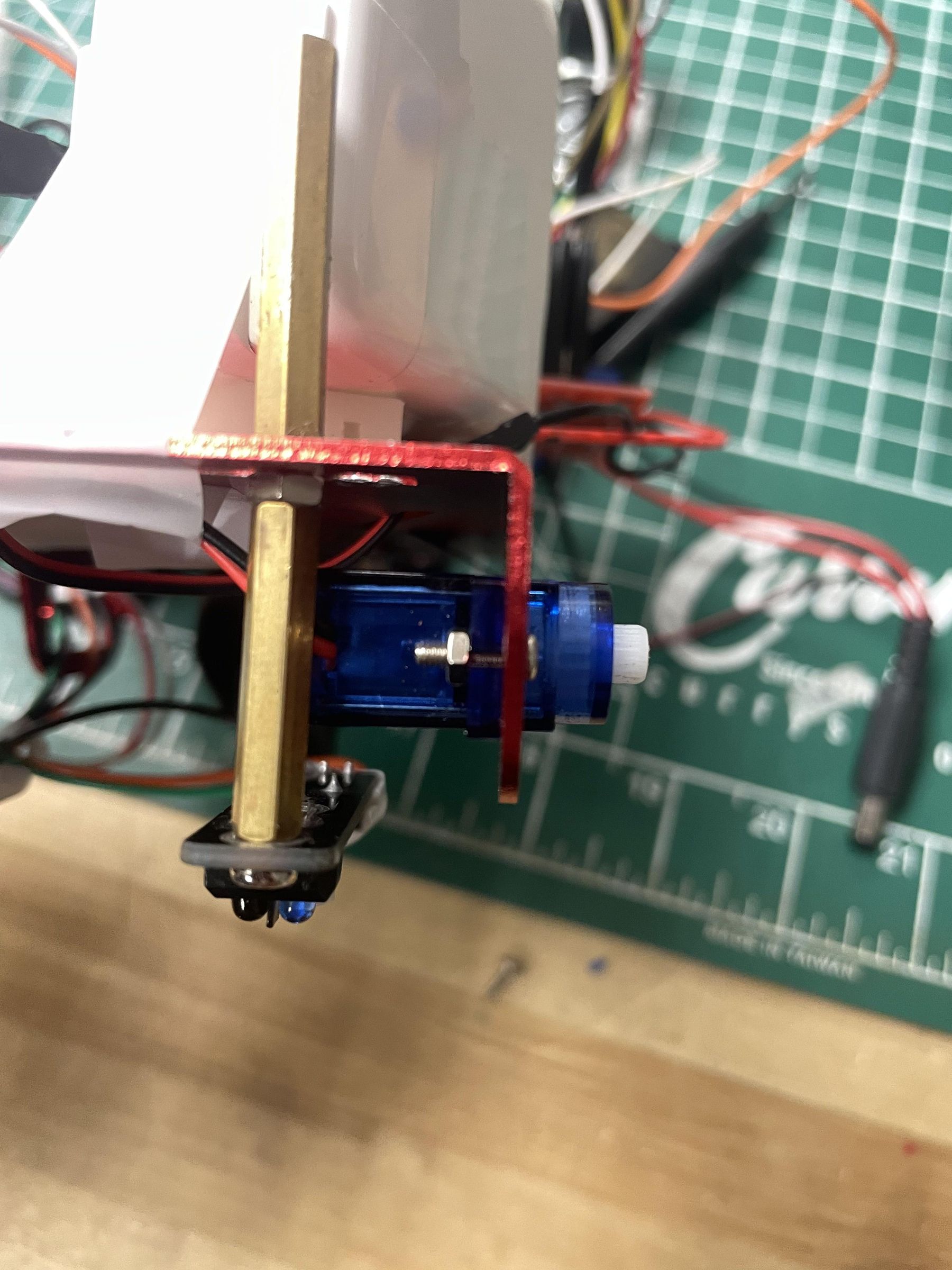
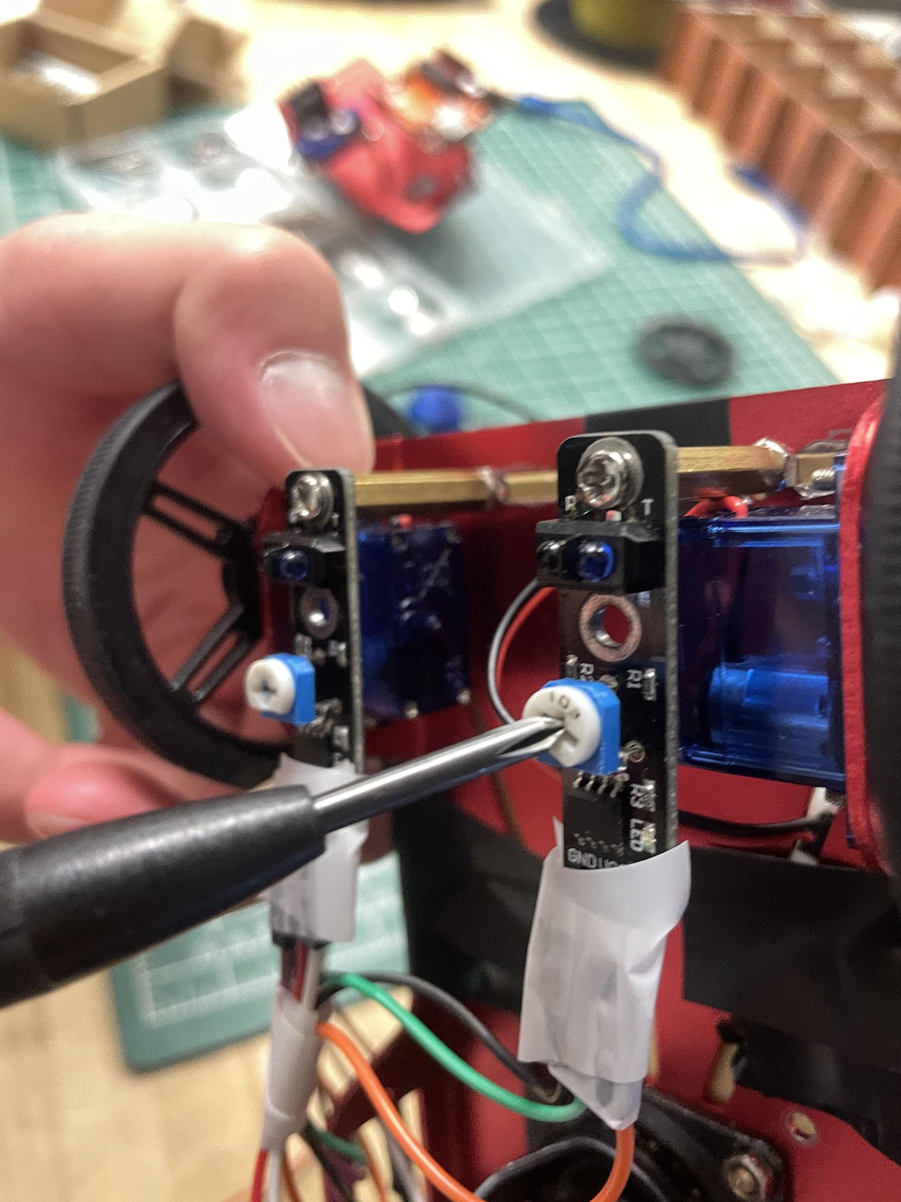
This is one of the trickiest parts about this project, as it's paramount that the Infared Sensors are both close to the floor, and spaced apart properly to account for the width of the electrical tape and some error.
The line-following system uses two TCRT5000 infrared reflective sensors. The sensors were mounted at the very front of the chassis between the two wheels.
These sensors emit infrared light, where white surfaces reflect more light and black surfaces reflect less. The Arduino reads the differences between these reflections to determine the sensor's position relative to the line.
Height:
Sensor placement is extremely important. To position the sensors as close as possible:
- Spacers were used for mounting.
- Washers were added to fine-tune the height.
The final sensor position placed them only a few millimetres above the floor, allowing for more accurate and reliable line detection.
Mounting the sensors onto the chassis is similar to steps 5 and 6, except now you're just doing it to the underside rather than on top. Locate the cut-out section between the wheels at the front of the chassis and position the sensor's screw holes directly under it. Insert a spacer in between and then screw on either side just enough so that the sensor doesn't fall out. Slide the sensors and spacers along the cutout until the distance between the two sensors is a bit longer than the width of the electrical tape. If the sensor isn't close enough to the floor, insert some washers into the spacers until a desirable height is reached.
Mount the Battery
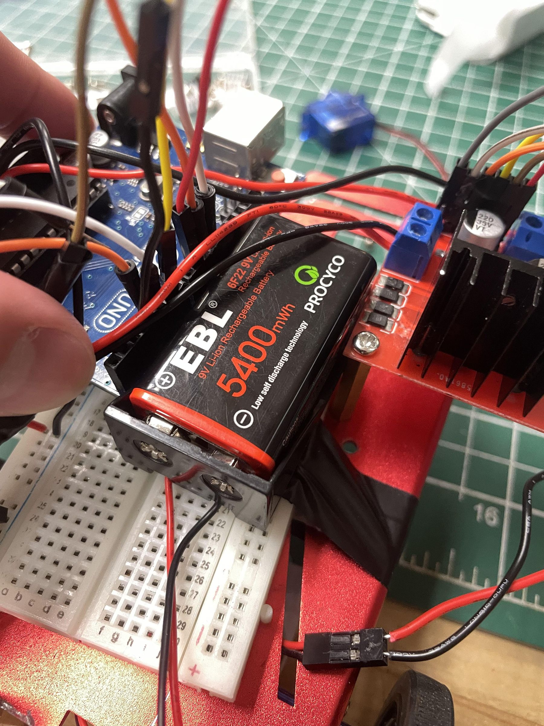
Now that every other component is mounted properly, you can look for a suitable location to mount the battery case. Make sure that this location is close to the L298N module.
To mount the battery, take the battery case and tape it to a chosen location on the chassis. A 12V battery will soon be able to be inserted into this case, powering the bot.
Wiring the Robot: Sensors
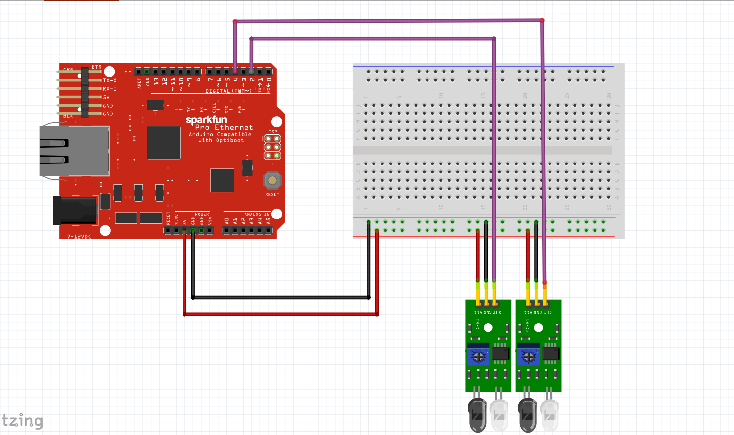
NOTE: Almost all wires in this build require male-to-female connections. However, if you are short on these specific types of wires, you can simply take a male-to-male wire and connect it to a female-to-female wire. Use electrical tape to secure the connection... Congrats! You've just made a male-to-female wire!
Power Connections
Left Sensor - (male-to-female wires)
- Connect the VCC pin of the left sensor to the positive power rail on the breadboard.
- Connect the GND pin of the left sensor to the negative power rail on the breadboard.
- Connect the OUT pin of the left sensor to Arduino Digital Pin 4.
Right Sensor - (male-to-female wires)
- Connect the VCC pin of the right sensor to the positive power rail on the breadboard.
- Connect the GND pin of the right sensor to the negative power rail on the breadboard.
- Connect the OUT pin of the right sensor to Arduino Digital Pin 2.
Breadboard Power - (regular wires)
- Connect the Arduino 5V to the positive breadboard rail.
- Connect the Arduino GND to the negative breadboard rail.
This allows both sensors to receive power from the breadboard while sending their output signals directly to the Arduino.
Wiring the Robot: L298N Module
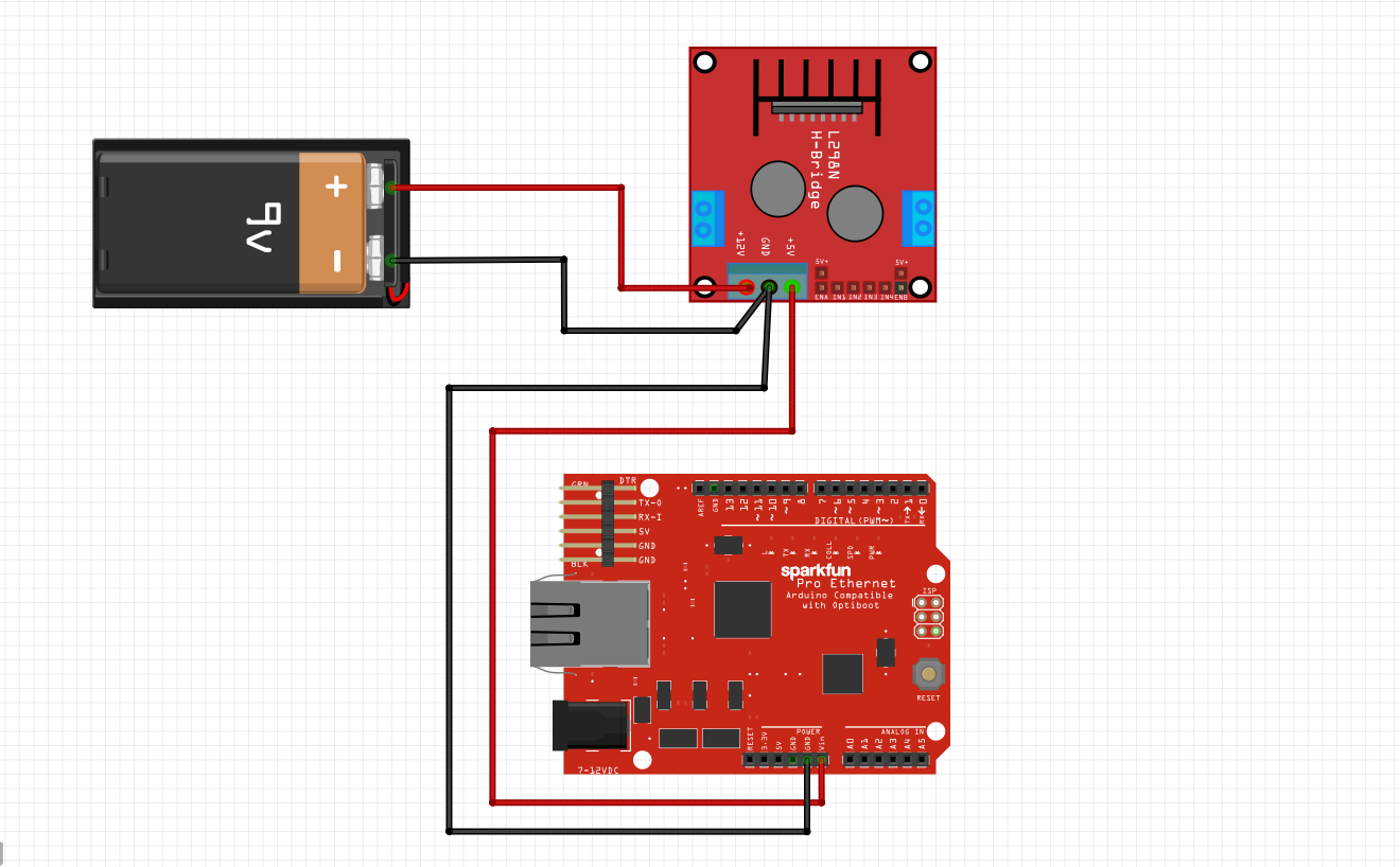
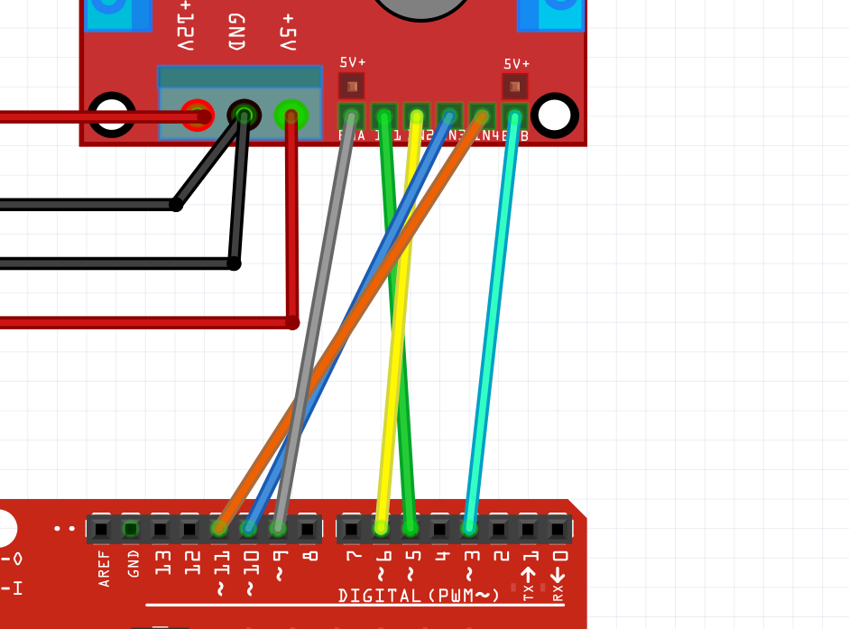
The L298N motor driver receives commands from the Arduino and controls both motors.
NOTE: The ENA and ENB connections on the L298N module require you to remove the case. To do this, simply take pliers or tweezers and pull the black caps off, revealing the pins underneath.
Control Signal Connections
Connect the following pins from the Arduino to the L298N:
Arduino Pin L298N Pin
Pin 5 | IN1
Pin 6 | IN2
Pin 10 | IN3
Pin 11 | IN4
Pin 9 | ENA
Pin 3 | ENB
ENA controls the speed of the left motor while ENB controls the speed of the right motor.
IN1 and IN2 control the direction of the left motor, while IN3 and IN4 control the direction of the right motor.
Power Connections
- Connect the positive terminal of the 12V battery to the +12V terminal on the L298N.
- Connect the negative terminal of the battery to the GND terminal on the L298N.
Arduino Connections
- Connect one Arduino GND pin to the GND terminal on the L298N with a regular wire. There should be two ground wires in the ground screw terminal of the L298N.
- Connect the 5V output of the L298N (leftmost screw terminal) to the Vin port of the Arduino. This will give the Arduino power.
Uploading Code
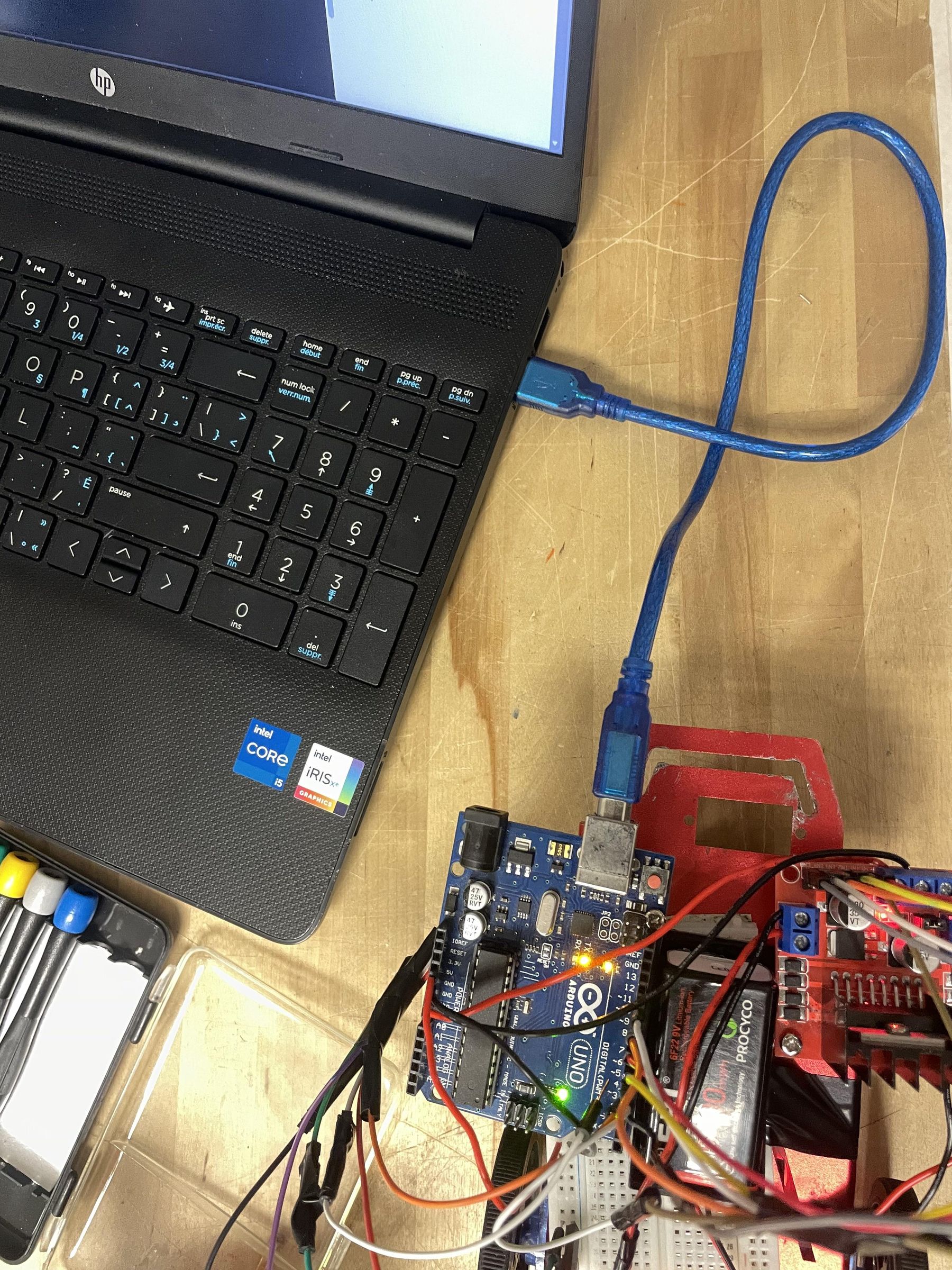
Before wiring the motors, you need to upload the code to the Arduino. This allows you to immediately test motor direction after wiring and make corrections on the spot.
How the code works:
The two IR sensors continuously read the floor beneath them. Based on what they detect, the Arduino tells the motors what to do:
- Both sensors on the line -- drive forward
- Only left sensor on the line -- turn left to correct
- Only the right sensor on the line -- turn right to correct
- Neither sensor on the line -- stop
The SPEED variable controls how fast the motors spin. It accepts values from 0 to 255. In code, vspeed controls forward speed and tspeed controls turn speed. Good starting values are 40 and 100, respectively. You can tune this later during testing.
To upload:
- Install the Arduino IDE on your computer if you haven't already
- Copy the full code below into a new sketch
- Connect your Arduino to your computer via USB
- Click Upload
Once uploaded, the Arduino is ready. You can now wire the motors in the next step and immediately verify their direction.
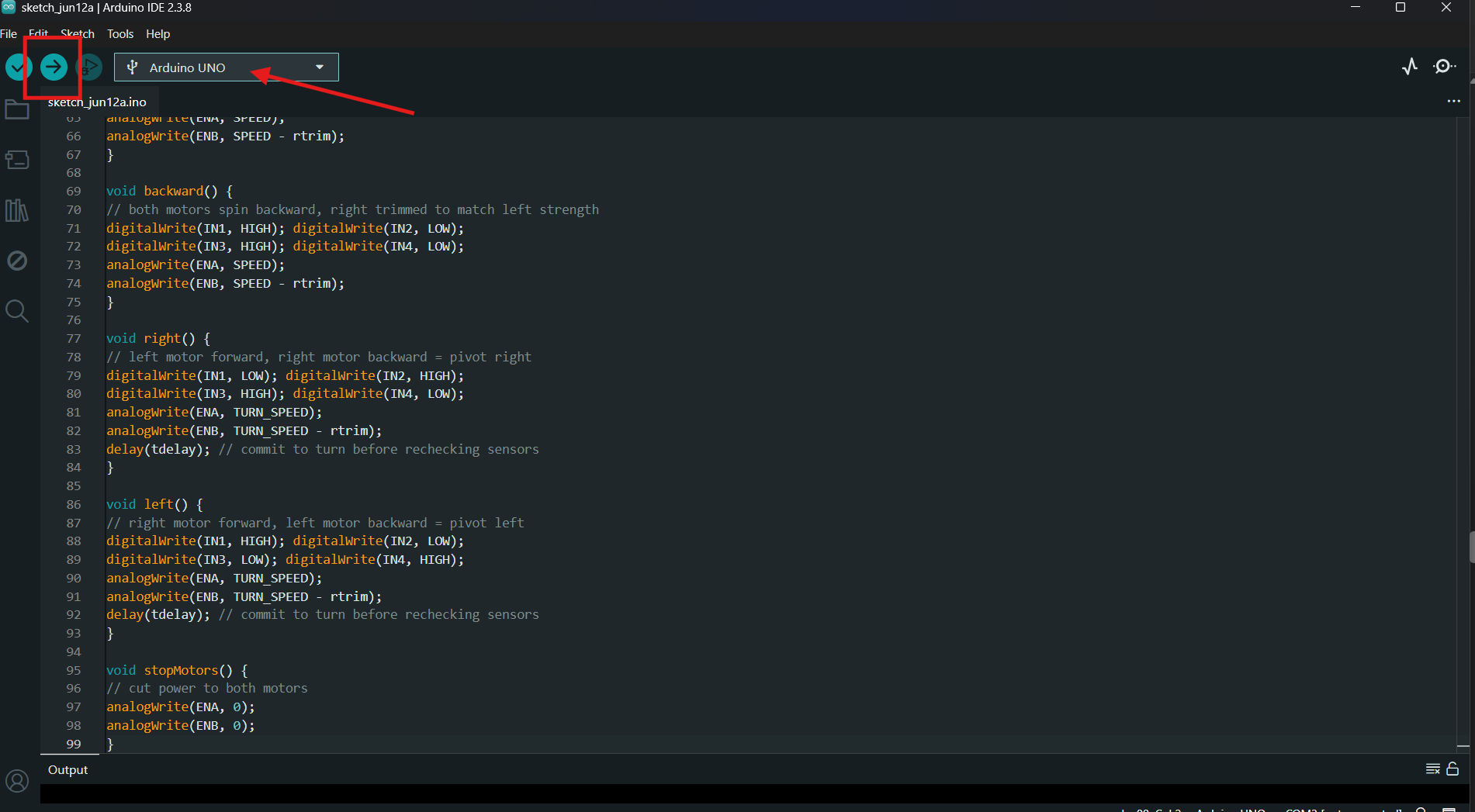
Important: When uploading, make sure that the correct port and Arduino are selected (red arrow). Once the code is finished and you've verified the correct settings, click the upload button (red square).
Code (I took inspiration from "Line Following Robot | Arduino Project Hub"):
Wiring the Robot: Motors
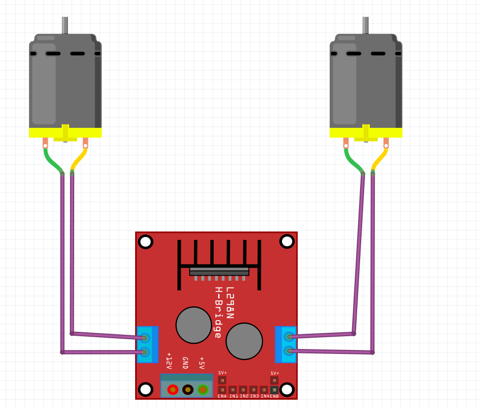
The two FM90 DC motors connect directly to the output terminals of the L298N.
Left Motor
Connect the two wires from the left motor to the L298N's:
- OUT1
- OUT2
Right Motor
Connect the two wires from the right motor to the L298N's:
- OUT3
- OUT4
If the motors are spinning in the wrong direction, don't worry. That's what we will be correcting in the next step!
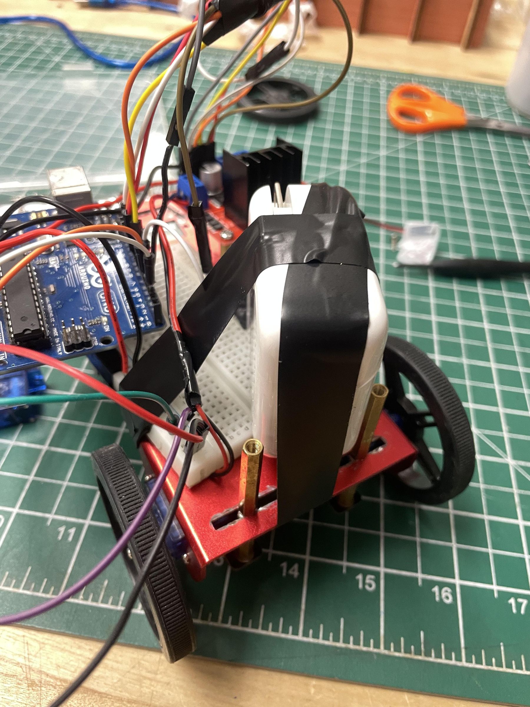
Now that you're done wiring the robot, the final result should look similar to:
Correcting Motor Direction
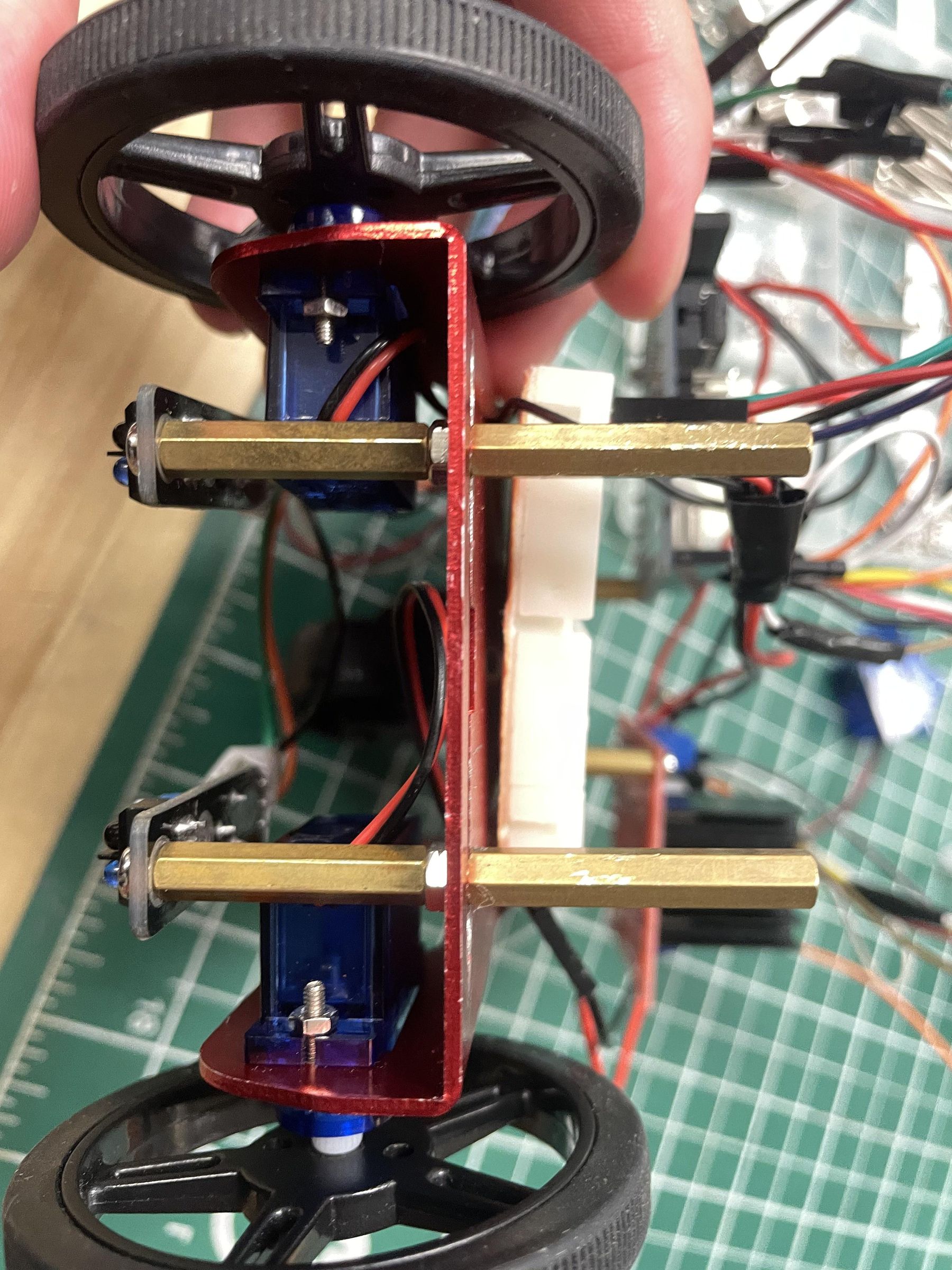
During testing, the motors initially rotated in the wrong directions.
To solve this issue, change the orientation of the wiring from the outputs of the L298N module to the motor, or recode the direction logic in the Arduino code.
Either solution is viable, and it depends largely on the builder's preference.
If you prefer to fix the direction in code rather than rewiring, locate the forward() function:
For each motor, swapping HIGH and LOW reverses its direction:
Apply the same swap to ml1/ml2 if the left motor needs reversing. Do this for all four motor functions: forward(), backward(), right(), and left().
Re-upload the code after making changes and test again.
Always verify motor direction before beginning line-following tests.
Balancing the Bot
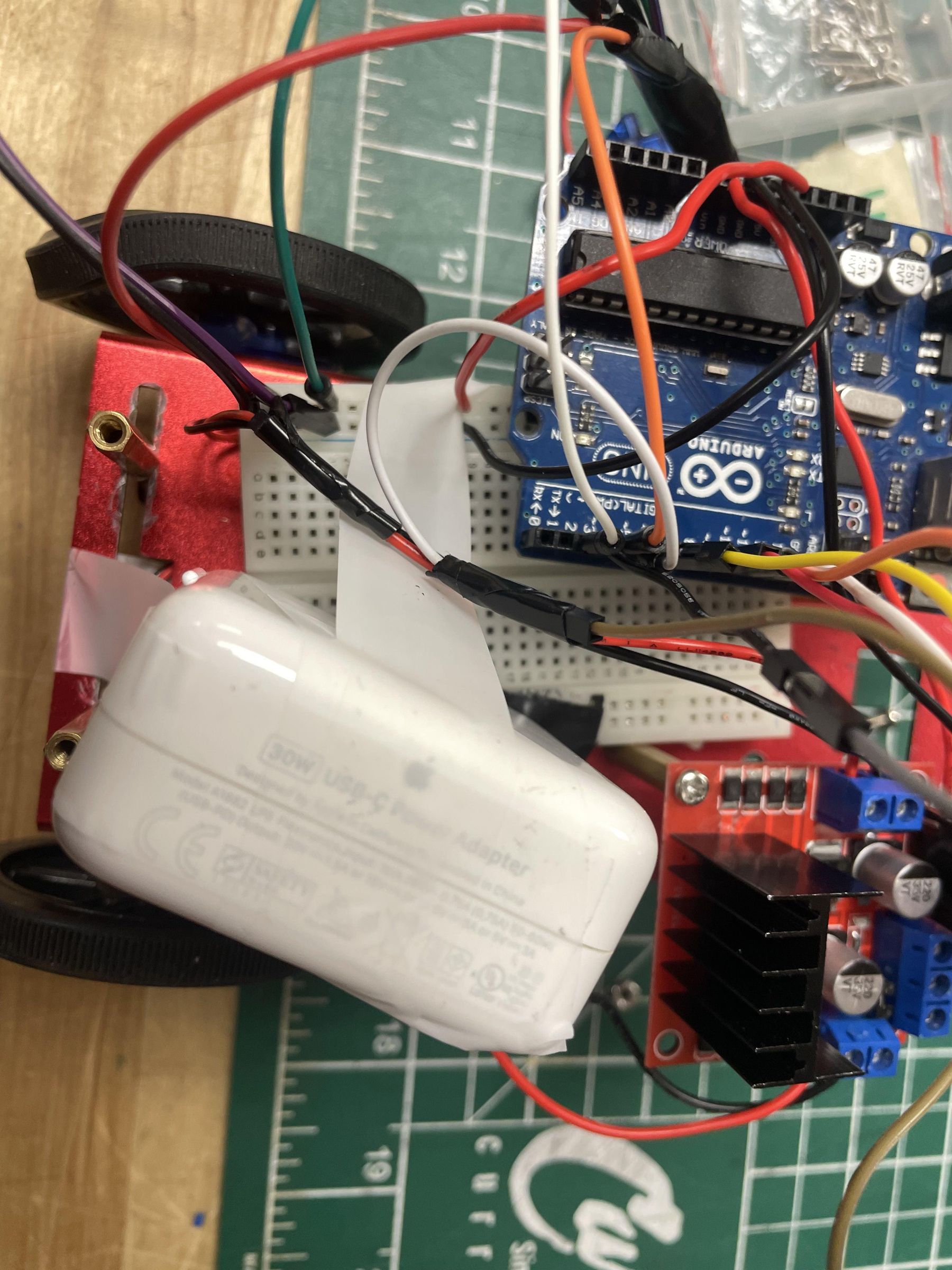
One unexpected problem involved uneven traction.
One wheel consistently maintained better contact with the floor and produced more forward motion than the other wheel.
This caused the robot to drift even when both motors were running.
Cause
The fixed mounting locations forced the Arduino and motor driver into positions that created an uneven weight distribution.
Solution
A counterweight was added to the lighter side of the chassis.
After adding the counterweight:
- Both wheels maintained better contact with the floor.
- Traction became more consistent.
- The robot drove significantly straighter.
This demonstrates the importance of proper weight distribution in mobile robotics.
Testing
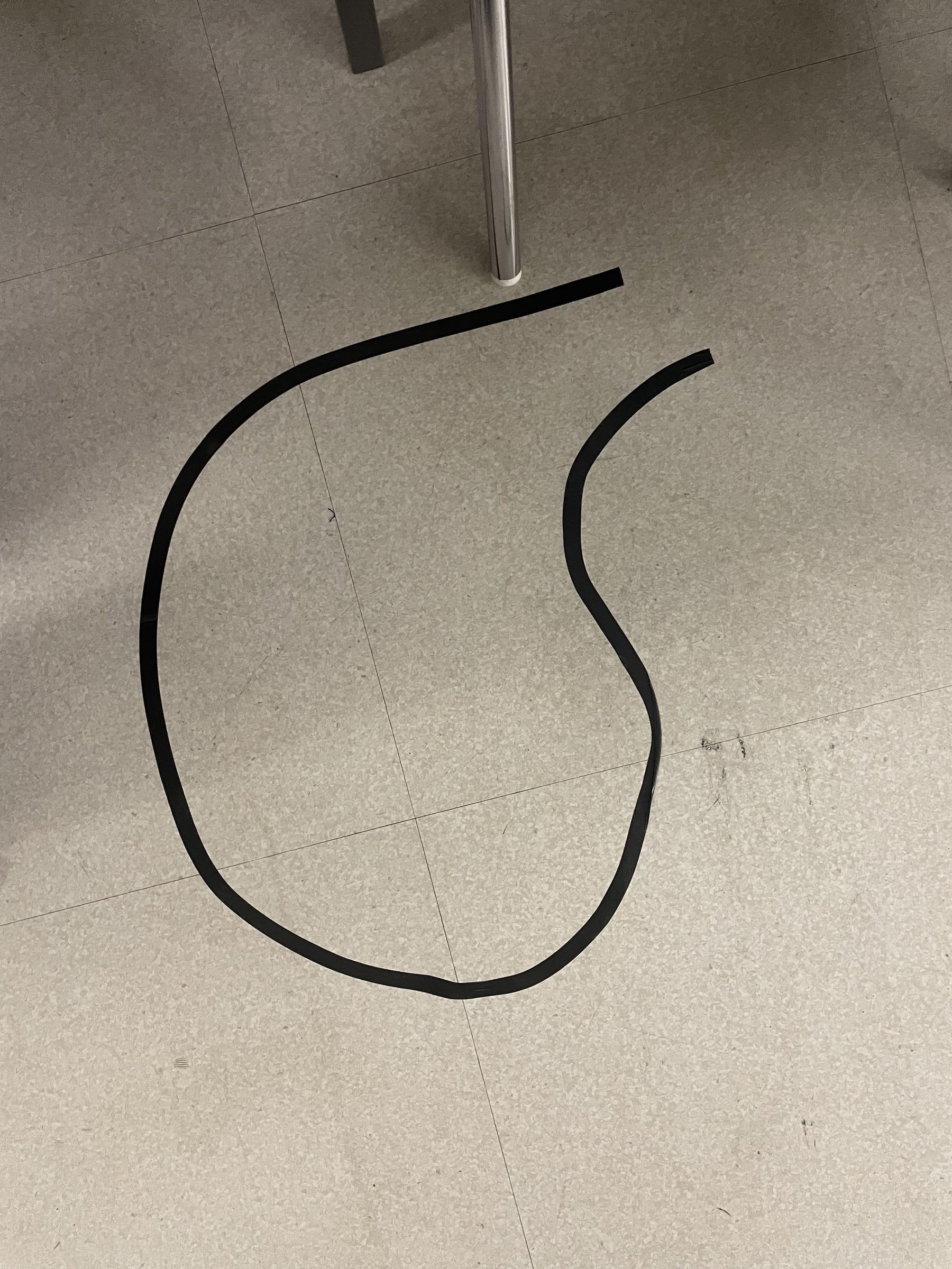
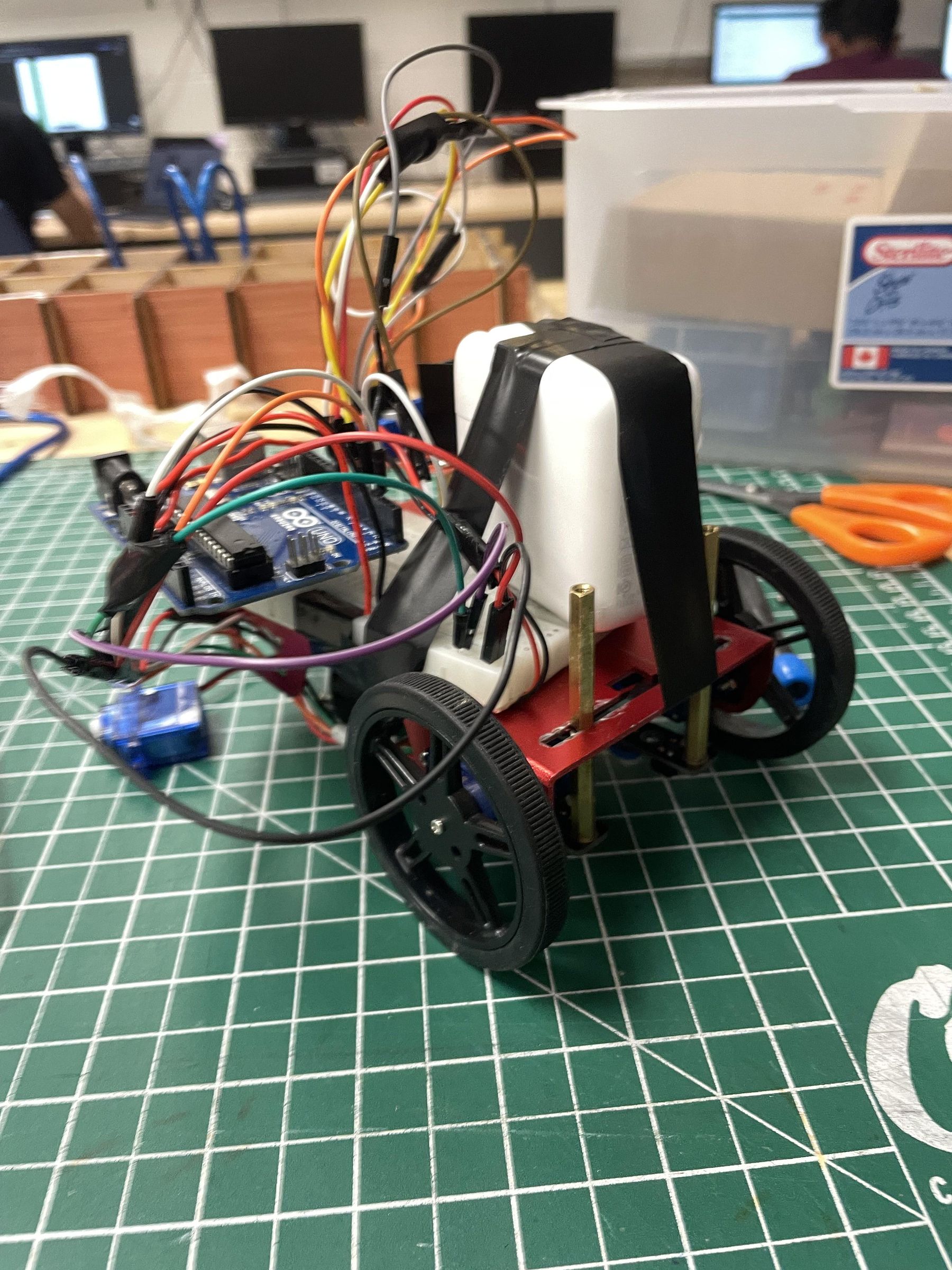
The robot was tested on a smooth, white marble-like floor.
The line was created using black electrical tape.
This combination worked well because the sensors could clearly distinguish between the dark tape and the light floor.
Testing Procedure
- Place the robot over the tape.
- Turn on the power.
- Observe the sensor responses.
- Adjust sensor height if needed.
- Verify turning behaviour.
Sensor Calibration
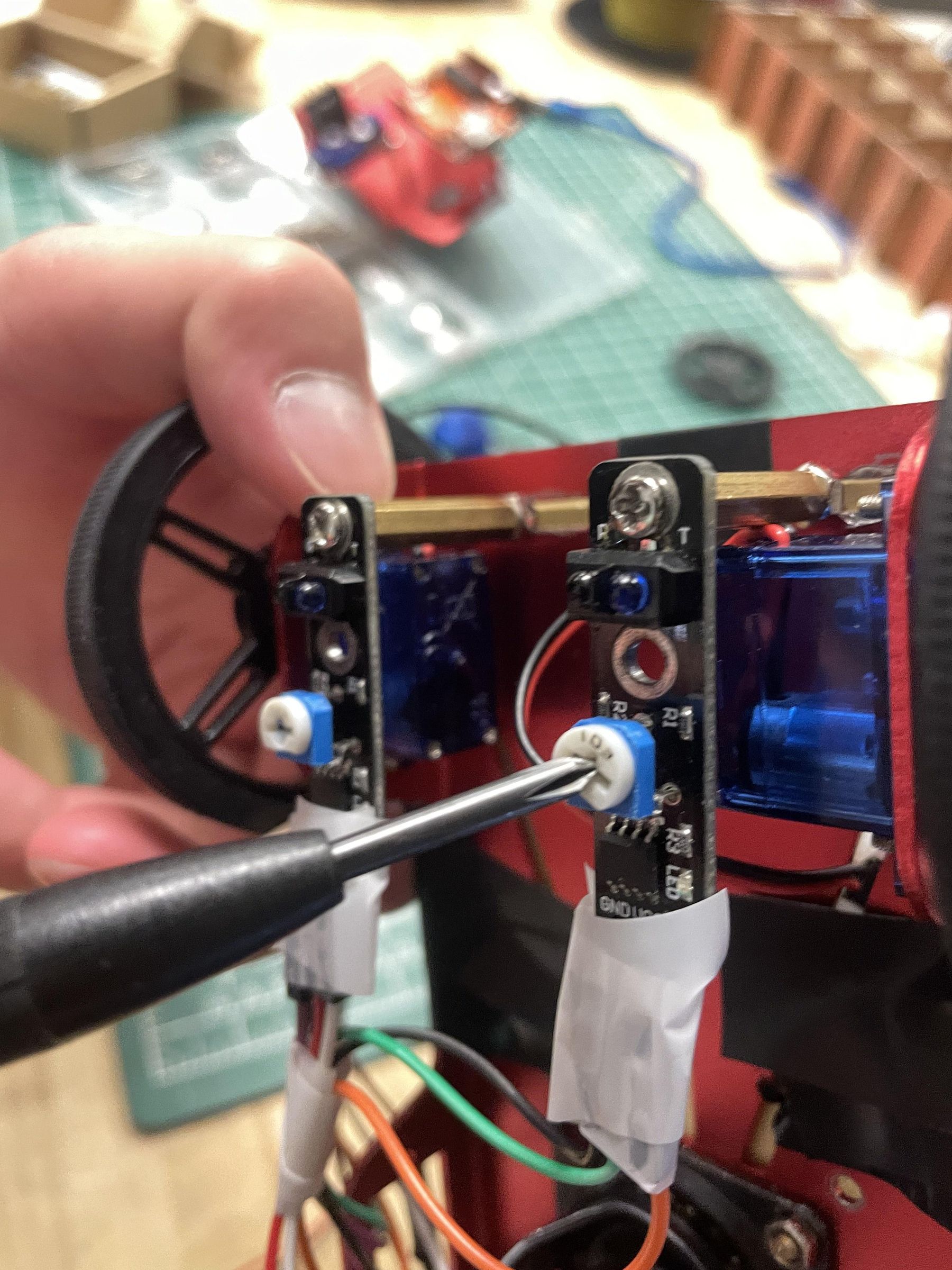
The TCRT5000 sensors include adjustable potentiometers (white knobs with a line across the middle for flathead).
Calibration can improve:
- Detection accuracy
- Response speed
- Reliability under different lighting conditions
To calibrate sensors, turn the potentiometers with a flathead until an optimal test result is produced.
Always calibrate sensors on the same surface that will be used during operation.
Troubleshooting
Robot Does Not Move
- Check battery voltage.
- Verify power connections.
- Ensure the motor driver is receiving power.
Robot Turns the Wrong Direction
- Verify motor wiring.
- Reverse motor logic in the code.
Robot Loses the Line
- Lower the sensors.
- Reposition the sensors.
- Calibrate the TCRT5000 modules.
Robot Drifts to One Side
- Check wheel traction.
- Verify motor operation.
- Adjust weight distribution.
Robot Stops Randomly
- Inspect all wiring connections.
- Secure loose wires using electrical tape.
- Verify jumper wire connections.