Arduino Memory Game
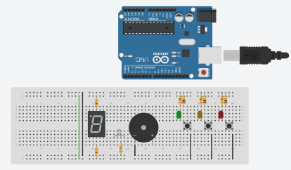
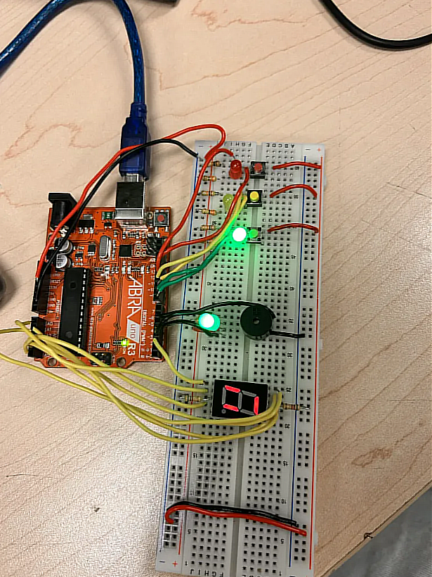
This project is a memory game built with an Arduino, designed to improve memory and reaction time by having the player repeat a random sequence of flashing LEDs.
At the start of the game, the Arduino generates a random colour sequence, with each colour tied to a specific LED, button, and tone. The sequence is displayed through flashing LEDs and buzzer sounds while the RGB LED glows blue, signalling the player to watch rather than act.
If the player repeats the sequence correctly, the RGB LED briefly flashes green and the game advances to the next round, growing the sequence by one colour each time to raise the difficulty. If the player presses the wrong button or runs out of time, the RGB LED turns red, a failure sound plays, and the game resets.
Throughout play, a 7-segment display shows the current round number, giving the player clear visual feedback on their progress.
I chose this project because it combines many of the components and concepts covered in class — LEDs, buzzers, and displays — into one functional, playable game.
Supplies
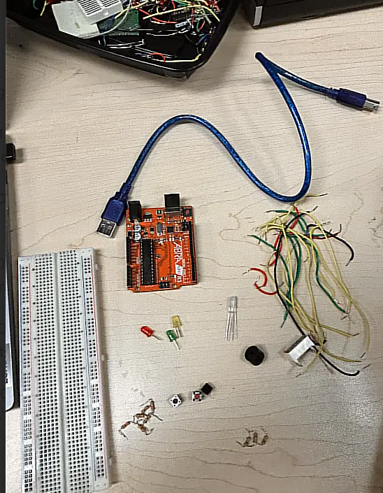
Within the Memory Game Arduino Project, these are the list of components that are essential to making this work:
- Arduino Uno
- Breadboard
- 3 Push Buttons
- 3 LEDs (Red, Yellow, Green)
- 3 10kΩ resistors (For Buttons)
- Piezo Buzzer
- 7-segment display (Common Anode)
- 6 330 resistors (For LEDs, Seven Segment and RGB LED)
- USB Cable
Connecting Power and Ground
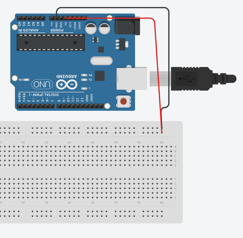
All components share a common ground, and the Arduino's 5V output powers components like the RGB LED's green pin where needed. Given the number of components and pins involved, keeping the breadboard layout clean and organized is highly recommended to avoid confusion.
Wire the Buttons
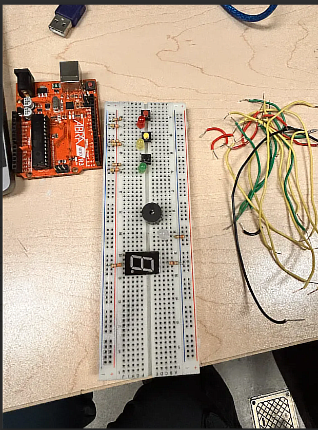
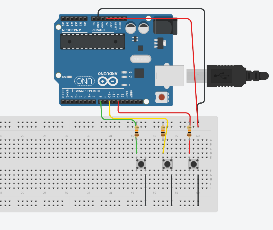
Connect the three push buttons, which serve as the player's input, to their own digital pins — red to pin 13, yellow to pin 11, and green to pin 9. When a button is pressed, it sends a HIGH signal that the Arduino reads to determine the player's choice.
Wire the LEDs
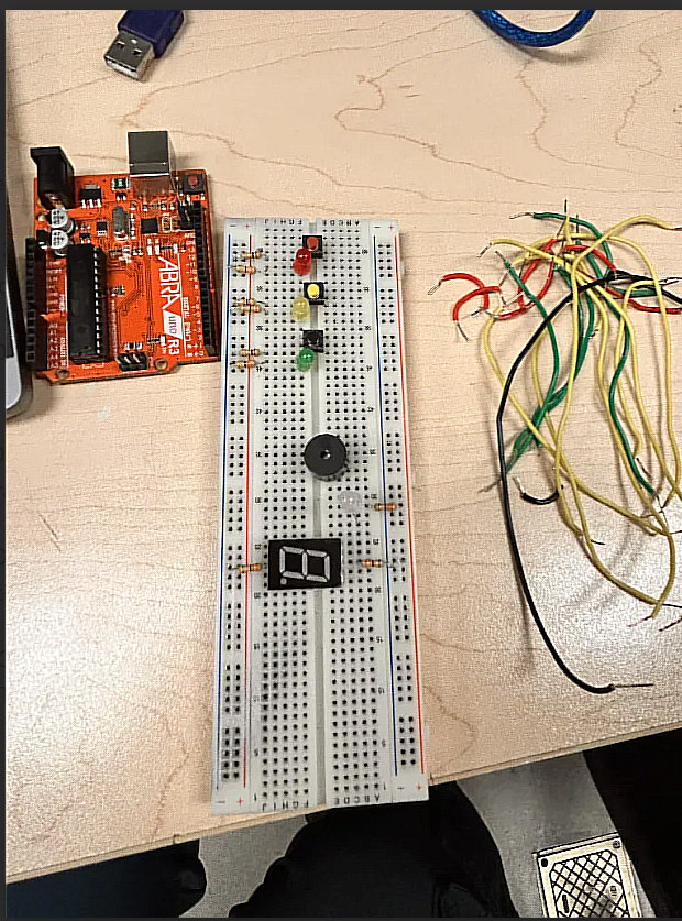
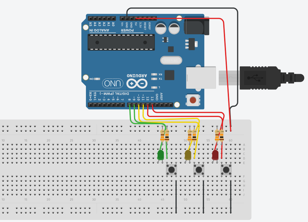
Connect each LED in series with a 330Ω resistor to limit current and protect the Arduino — red to pin 12, yellow to pin 10, and green to pin 8. For each LED, connect the cathode (short leg) to GND through the resistor, and connect the anode (long leg) to its assigned Arduino pin.
Wire the Buzzer
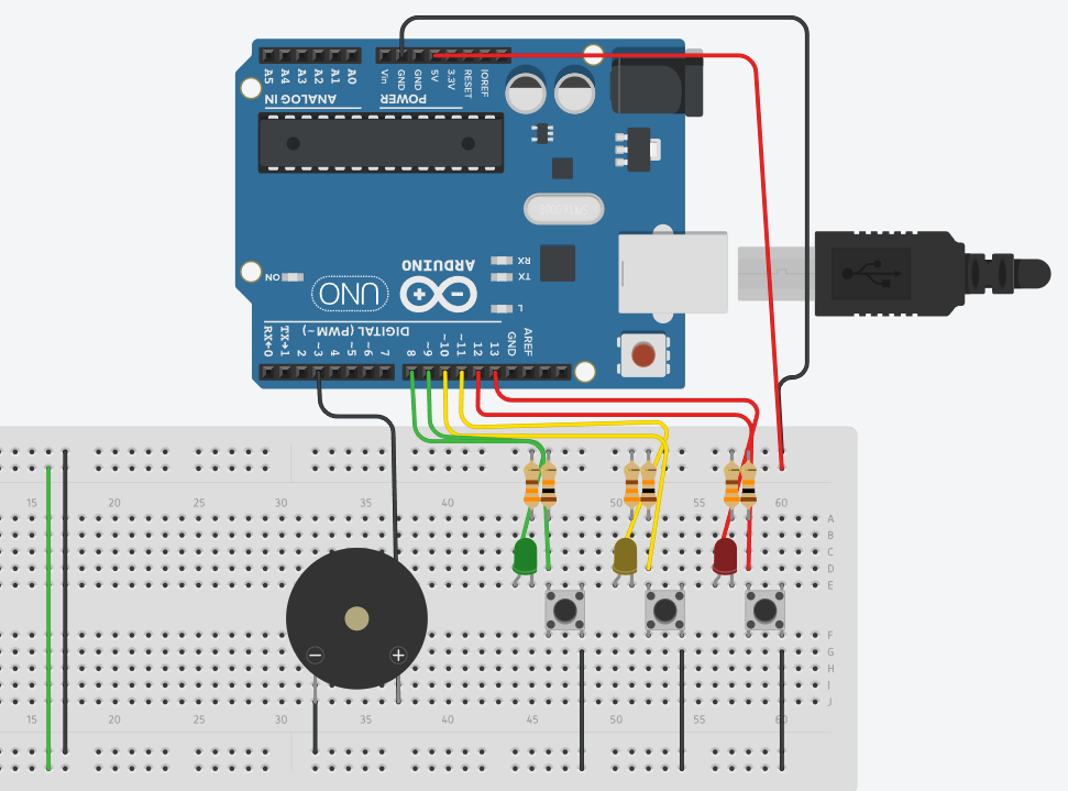
Connect the buzzer's positive pin to digital pin 3 on the Arduino, and connect its negative pin to GND to complete the circuit. This buzzer provides the audio feedback for the game, sounding a distinct tone for each colour both while the sequence is being played back to the player and whenever a button is pressed during gameplay. This auditory cue reinforces the visual feedback from the LEDs, making the sequence easier to follow and giving the player an extra layer of confirmation that their input has been registered correctly.
Wire the Seven-segment Display
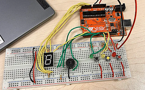
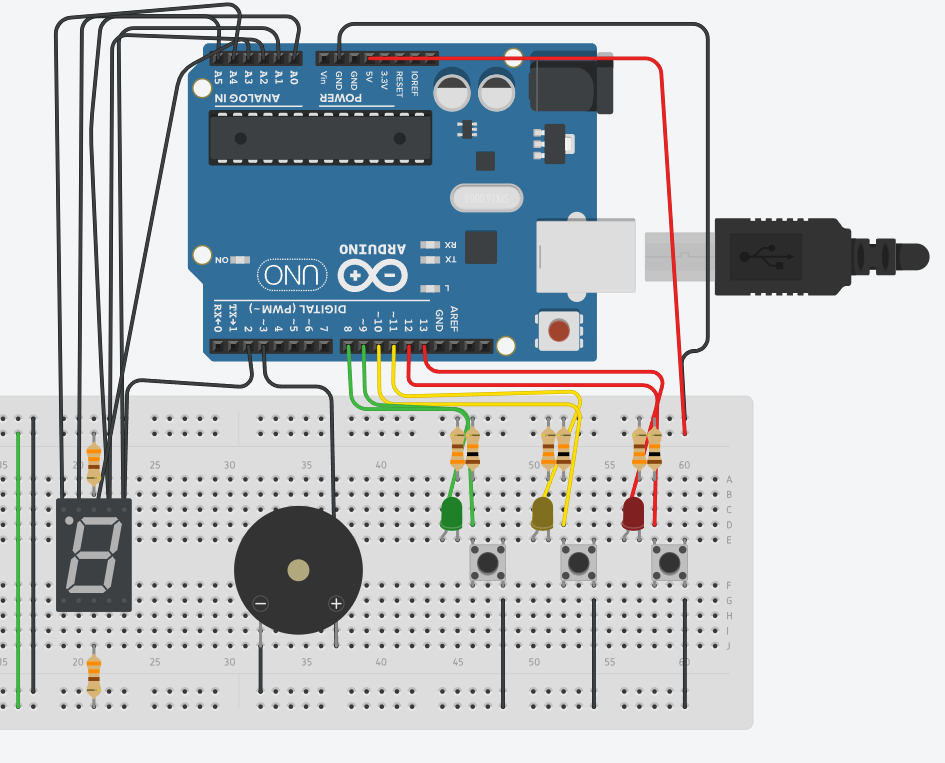
Connect each of the seven segments (A–G) to its own pin, using several analog pins (A0–A5) as digital outputs since the Arduino has a limited number of digital pins available.
Connect:
- a to A3
- b to A4
- c to A5
- d to A0
- e to digital pin 2
- f to A2
- g to A1
Run each of these connections through a 330Ω resistor to limit current and protect both the display and the Arduino. Before powering on, double-check that the display is oriented correctly on the breadboard, since most 7-segment displays look symmetrical at a glance — wiring it backward can cause the digits to appear reversed, mirrored, or malformed entirely, making the round counter difficult or impossible to read.
Wire the RGB LED
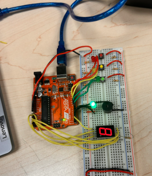
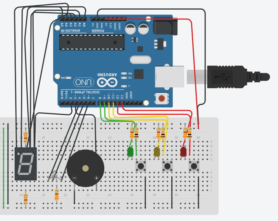
Since this project uses a common anode RGB LED, connect its green pin directly to the 5V supply, since it stays permanently lit. Then connect the red channel to pin 6 and the blue channel to pin 5, since these are the only two channels actively controlled by the Arduino. Once wired, this LED will glow blue while the pattern plays, green for a correct input, and red for an incorrect input or game over.
Code
At the top of the sketch, all the pins for the buttons, LEDs, buzzer, RGB LED, and 7-segment display are declared, along with the game variables that track the sequence, the current round, the time limit, and whether a game is in progress. Declaring everything here keeps the hardware setup and game state easy to manage as the code grows.
The RGB LED is controlled through four helper functions: rgbOff(), rgbBlue(), rgbGreen(), and rgbRed(), each of which uses analogWrite() to set the red, blue, and green channels. Since this is a common anode RGB LED, a value of 255 turns a channel off while 0 turns it fully on, so rgbBlue() lights up during sequence playback, rgbGreen() confirms a correct press, and rgbRed() signals that the player has lost.
The setup() function runs once when the Arduino powers on. It seeds the random number generator using randomSeed(analogRead(A0)) so that each game produces a different sequence, and then sets every button, LED, buzzer, RGB, and display pin to its correct input or output mode.
A set of digit functions, smiley() and one() through nine(), each turn the seven display segments on or off in a specific pattern to form a shape, allowing the game to show either the current round number or a smiley face on the start screen.
Two more functions handle the LED and buzzer playback: flashLED() lights the correct LED and plays its matching tone for a given colour, while allLEDoff() turns every LED off and silences the buzzer using noTone(). Together, these two functions drive the visual and audio playback of the sequence during each round.
Player input is read through buttonCheck(), which checks all three buttons and uses a short twenty-five millisecond delay to debounce each press, confirming it's a genuine press rather than electrical noise, before sounding its tone and returning which colour was pressed, or returning 3 if nothing was pressed.
When the game is idle, startSequence() waits for any button to be pressed to begin a new game. Once triggered, it fills buttonSequence[] with a freshly generated random sequence, flashes all three LEDs in a quick "get ready" animation, and then displays the smiley face while clearing the RGB LED.
If the player loses or wins, loseSequence() or winSequence() plays a short melody, descending for a loss and ascending for a win, while lighting the RGB LED red or green respectively, before resetting gameStarted back to false so the game can be played again.
Finally, the loop() function ties all of these pieces together. It displays the current round number using the roundDisplay[] array of function pointers, plays back the sequence using flashLED() at a speed that increases as roundCounter grows, and then waits for the player to respond using buttonCheck(). Each press is compared against buttonSequence[], with a correct match advancing the round and an incorrect press or a timeout, tracked using millis(), ending the game. Once roundCounter reaches roundsToWin, winSequence() is triggered and the player wins.
Credit for original code and inspiration here
Downloads
Refining Phase
Throughout the development of this Memory Game project, I made several refinements to improve the overall performance of both the circuit and the code.
1. Missing Green RGB Pin In the researched project, the green RGB pin was never declared or wired, even though a tone was already assigned to it. I added:
- const int green_RGB = 4; — declares the Arduino pin
- analogWrite(green_RGB, 255); — keeps it off while the player's sequence hasn't been confirmed yet
- analogWrite(green_RGB, 0); — turns it on once the player's input is correct
These additions made the green RGB pin function properly, preventing the system from displaying the wrong colour during sequence confirmation.
2. Resistor Placement In the researched breadboard layout, the resistors for the buttons and LEDs were misplaced, failing to limit current properly and risking a circuit short. I repositioned them so each resistor runs alongside its component to GND — each LED draws power from its button and has its cathode grounded through a 330Ω resistor, with the same approach applied to the buttons. The Arduino pin now sits between each component (button or LED) and its resistor for cleaner positioning.
3. Resistor Value I changed the resistor value from 560Ω to 330Ω, allowing more current to flow through the RGB LED and 7-segment display while staying within safe limits. This makes the indicators noticeably brighter and easier to see during gameplay.
4. RGB LED Placement I positioned the RGB LED away from the Arduino and the main game LEDs to improve visibility and clearly separate game-status feedback from the sequence LEDs. This creates a cleaner layout and makes it easier for the player to tell whether a round is playing, succeeding, or ending.
5. Improved Randomness I enabled randomSeed() in the setup function. In the original version, this line was commented out, causing the Arduino to generate the same sequence every time it reset. With seeding enabled, every game now produces a unique sequence.
6. Dynamic Difficulty Finally, I added dynamic difficulty scaling. The original version played the sequence at a constant speed throughout, whereas in my refined version, the display speed gradually increases as the player advances through rounds, making later stages more challenging and engaging.
Common Mistakes
Here are some mistakes to watch out for when building this circuit.
- Buttons not responding: Usually caused by incorrect grounding or a missing input configuration. Make sure each button is properly connected between its input pin and ground.
- LEDs not lighting properly: Usually caused by incorrect LED orientation or a missing resistor. Check that each LED is wired the right way around with its resistor in place.
- 7-segment display issues: Often caused by incorrect wiring or a common anode/cathode mismatch. If this happens, the segment logic in the code needs to be inverted.
- RGB LED not changing correctly: Usually caused by incorrect pin assignments or confusion over the RGB type. In a common anode setup, the logic is inverted, so LOW turns the LED on instead of HIGH.
Works Cited
Works cited:
Tarundeep. K. (2021, February 4). ARDUINO MEMORY GAME. Instructables. https://www.instructables.com/ARDUINO-MEMORY-GAME-2/
Yeung, C. (2026). Tinkercad. https://www.tinkercad.com/things/6mNNcqrMbJv-overhaul-circuit/editel?returnTo=https%3A%2F%2Fwww.tinkercad.com%2Fdashboard&sharecode=QY8IFYvqd2mj2Hourh5G2NAKcpInwVb7ymJHdX9Rp_E
Arduino Reference. tone().
https://docs.arduino.cc/language-reference/en/functions/advanced-io/tone/
Arduino Reference. DigitalWrite().
https://docs.arduino.cc/language-reference/en/functions/digital-io/digitalwrite/
Theory
Circuit Theory
This project relies on a mix of digital and analog I/O on the Arduino Uno. The three buttons are read as digital inputs, sending a HIGH signal when pressed. The LEDs and buzzer are digital outputs, with resistors limiting current to protect both the LEDs and the board. The RGB LED is common anode, meaning it uses inverted logic — a value of 255 turns a channel off, while 0 turns it fully on. Since the Arduino has limited digital pins, several analog pins (A0–A5) are reused as digital outputs to drive the 7-segment display, which lights specific segment combinations to show numbers or a smiley face. All components share a common ground to complete the circuit.
Code Theory
The game follows a simple loop: generate a random sequence, play it back, then wait for the player to repeat it. random(0,3) builds the sequence, seeded once at startup so it differs each run. Playback flashes each LED and plays its matching tone; input is read with a short debounce check to confirm real button presses. Each press is compared against the expected value — correct presses advance the round, while a wrong press or a timeout (tracked via millis()) ends the game. The RGB LED reflects state throughout (blue = playback, green = correct, red = game over), and rounds get faster as roundCounter increases. The game ends in a win after 9 rounds or a loss on any mistake.
Enjoy
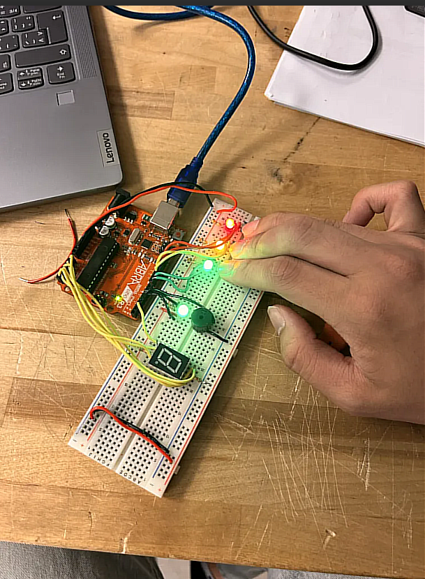
Once everything is wired up and the code is uploaded, double-check all your connections, then power on the Arduino. Press any button to start the game, watch for the smiley face and the first colour to flash, and try to repeat the growing sequence correctly each round. See how many rounds you can survive, and have fun!