Arduino Mini Unleashed - Arduino Mini for Beginners
by ahmedebeed555 in Circuits > Arduino
1255 Views, 3 Favorites, 0 Comments
Arduino Mini Unleashed - Arduino Mini for Beginners

Hello and welcome to instructables, I really want to share those new projects I make even they were not so unique but sharing what I make keeps me feeling alive.
So, if you like this instructable please
Leave a comment,
Share with your friends,
Favorite the instructable,
Follow me to see new instructables,
Visit my website
( even if you don't buy any thing - don't worry. I'm not selling any thing - No spam. Only useful stuff )
That's a long To-Do list. Choose what you want. And thanks again for reading my instructable.
So Let's get started.
Recently, I bought Arduino Mini Pro Kit. In this instructable, I'll show you how to use this magnificent Arduino Module.
Here, I'm only showing beginner how to get started with this kit. Keep tuned for the next instructables of projects using Arduino Mini.
You can get this Module from Banggood, ebay, Amazon UK, Amazon FR or Amazon DE
Here is my Channel on Youtube:
AeroArduino
Supplies
Out of the Box


The Arduino mini comes with pin header on both sides and on the front. You need to solder these pin headers on the board.
You can find many courses on soldering online.
How to Program


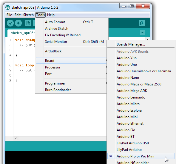
In Arduino IDE choose board Arduino mini pro.
Note:
Arduino mini board has no built in USB interface. So you need to connect it to another board that converts serial communication signals into USB signals.
A good example of such boards is FTD USB.
Another example is foca which I used here and will show the connection to Arduino mini board.
Connect Foca or FTD232 to Arduino mini as follows
FTD232 <------------------> Arduino Mini
3.3v ------------------------ VCC
GND ------------------------ BLK
RXD ------------------------ TXD
TXD ------------------------ RXD
DTR ------------------------- GRN
Hello World

Just like in the programming world. You start your learning process with a program called Hello World That does nothing except printing "Hello World" on the Computer Monitor.
The Blink example is the same analogue in Embedded Systems World.
You can start your programming learning process and checking that all software and hardware are both working correct.
This is done by blinking an LED with a predetermined rate you choose.
Open Arduino IDE and select
Select Tools ----> Board ------> Arduino Pro or Pro Mini
Select File ------> Examples -----> 01.Basics ------> Blink
/*
Blink Turns on an LED on for one second, then off for one second, repeatedly.
Most Arduinos have an on-board LED you can control. On the Uno and Leonardo, it is attached to digital pin 13. If you're unsure what pin the on-board LED is connected to on your Arduino model, check the documentation at http://www.arduino.cc
This example code is in the public domain.
modified 8 May 2014 by Scott Fitzgerald
*/
// the setup function runs once when you press reset or power the board void setup()
{
// initialize digital pin 13 as an output.
pinMode(13, OUTPUT); }
// the loop function runs over and over again forever void loop()
{
digitalWrite(13, HIGH); // turn the LED on (HIGH is the voltage level)
delay(1000); // wait for a second
digitalWrite(13, LOW); // turn the LED off by making the voltage LOW
delay(1000); // wait for a second
}
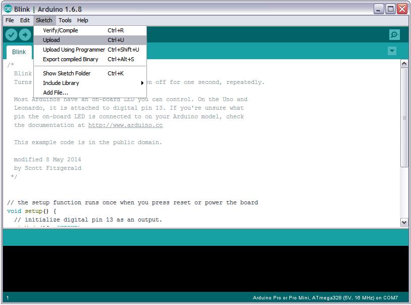
Select Sketch----- > Upload
Software Serial
https://www.arduino.cc/en/Tutorial/SoftwareSerialExample
In this example, you can use the Arduino Mini as a serial USB device that echos input you give to the keyboard.
Although this is not actually useful, but it enables you to use Arduino Mini Serial capabilities. This can be used to input USB commands to the Arduino Mini circuit application or you can read data from it to your computer on the serial monitor application.
Hardware Required:
Arduino Mini Board
Circuit
There is no circuit for this example. Make sure that your Arduino or Genuino board is attached to your computer via USB to enable serial communication through the serial monitor window of the Arduino Software (IDE).
Code
/* Software serial multple serial test
Receives from the hardware serial, sends to software serial. Receives from software serial, sends to hardware serial.
The circuit: * RX is digital pin 10 (connect to TX of other device) * TX is digital pin 11 (connect to RX of other device)
Note: Not all pins on the Mega and Mega 2560 support change interrupts, so only the following can be used for RX: 10, 11, 12, 13, 50, 51, 52, 53, 62, 63, 64, 65, 66, 67, 68, 69
Not all pins on the Leonardo and Micro support change interrupts, so only the following can be used for RX: 8, 9, 10, 11, 14 (MISO), 15 (SCK), 16 (MOSI).
created back in the mists of time modified 25 May 2012 by Tom Igoe based on Mikal Hart's example
This example code is in the public domain.
*/
#include SoftwareSerial mySerial(10, 11); // RX, TX
void setup() { // Open serial communications and wait for port to open: Serial.begin(57600); while (!Serial) { ; // wait for serial port to connect. Needed for native USB port only }
Serial.println("Goodnight moon!");
// set the data rate for the SoftwareSerial port mySerial.begin(4800); mySerial.println("Hello, world?"); }
void loop() { // run over and over if (mySerial.available()) { Serial.write(mySerial.read()); } if (Serial.available()) { mySerial.write(Serial.read()); } }