Arduino Nano Based Digital Multimeter (Measures DC Voltage, Resistance & Current)
by sandeepagrawal9368 in Circuits > Arduino
57 Views, 3 Favorites, 0 Comments
Arduino Nano Based Digital Multimeter (Measures DC Voltage, Resistance & Current)
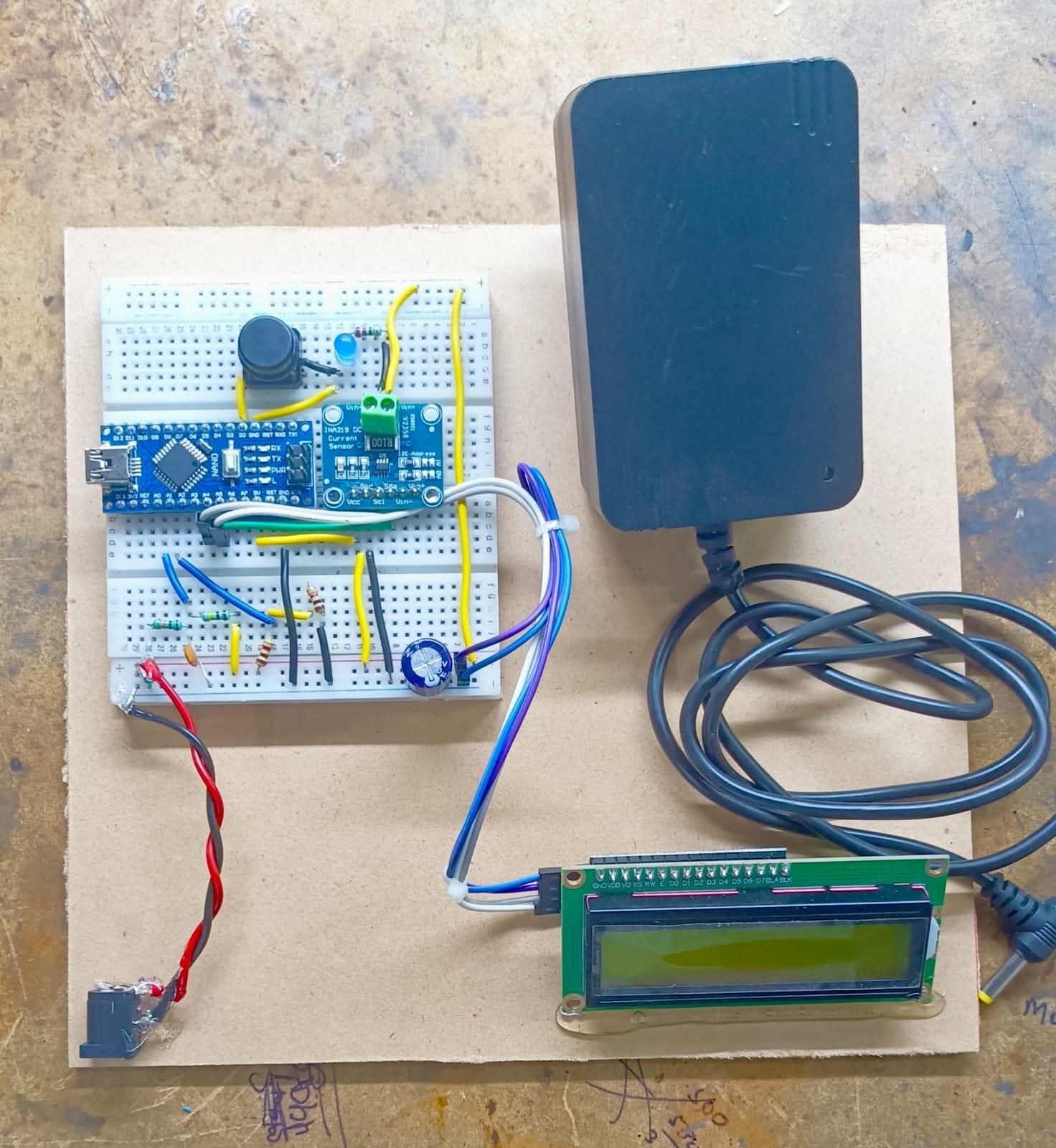
Measuring electrical parameters such as DC voltage, resistance, and current is a fundamental requirement in electronics. Commercial digital multimeters are widely available, but building one from scratch is an excellent way to understand analog signal processing, sensor interfacing, and embedded systems.
In this project, I designed and developed an Arduino Nano Based Digital Multimeter capable of measuring DC Voltage, Resistance, and DC Current. The system uses an Arduino Nano as the main controller, a 16×2 I²C LCD to display readings, a precision voltage divider for voltage measurement, a 1 kΩ reference resistor for resistance measurement, and an INA219 current sensor for accurate DC current measurement.
The multimeter features push-button mode selection, allowing the user to switch between Voltage, Resistance, and Current measurement modes. The hardware was calibrated and tested to improve measurement accuracy and provide stable readings.
This project is suitable for electronics students, beginners in embedded systems, and DIY enthusiasts who want to learn how digital measuring instruments work and how they can be implemented using Arduino.
Circuit Diagram
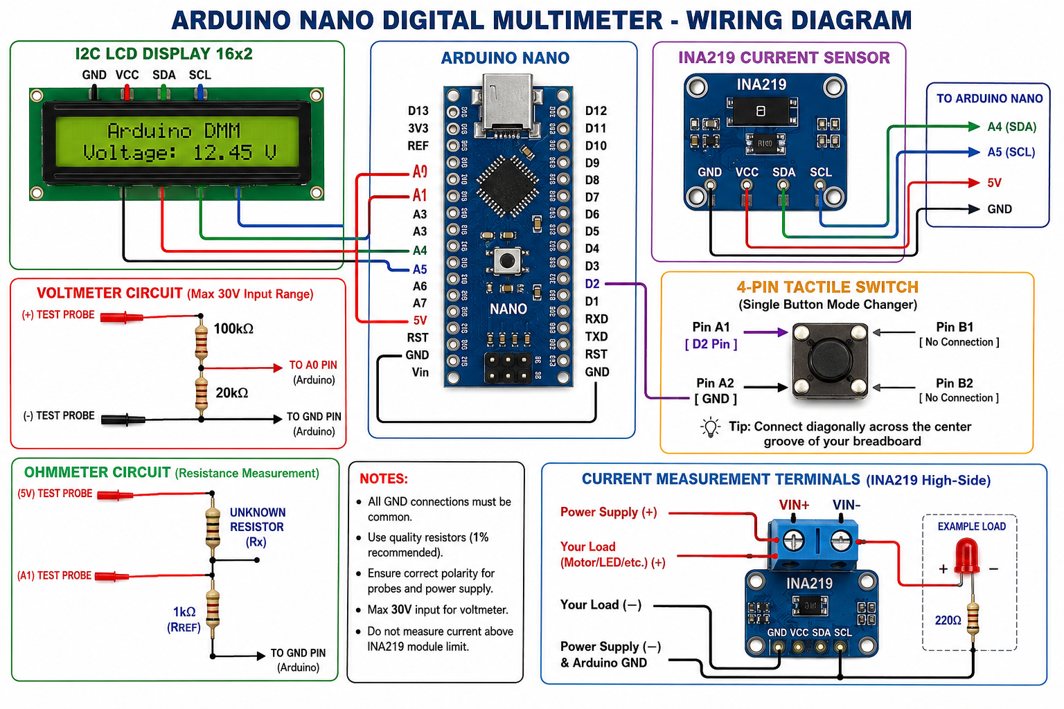
The Arduino Nano Based Digital Multimeter consists of three independent measurement circuits: DC Voltage Measurement, Resistance Measurement, and DC Current Measurement. Each circuit is connected to the Arduino Nano and selected using push buttons.
The DC Voltage Measurement circuit uses a 100 kΩ and 20 kΩ voltage divider to reduce the external input voltage to a safe level for the Arduino's analog input (A0). This allows the multimeter to measure higher DC voltages while protecting the microcontroller.
The Resistance Measurement circuit is based on the voltage divider principle. A precision 1 kΩ reference resistor is connected with the unknown resistor, and the voltage at the divider junction is measured through analog pin A1. The Arduino calculates the unknown resistance using the voltage divider equation.
The DC Current Measurement circuit uses the INA219 High-Side Current Sensor Module. The load is connected in series with the INA219 through the VIN+ and VIN− terminals. The sensor communicates with the Arduino Nano via the I²C interface (SDA and SCL) to provide accurate current measurements.
A 16×2 I²C LCD is used to display the measured values. Three push buttons allow the user to switch between Voltage, Resistance, and Current measurement modes.
The circuit is powered using a 5 V USB supply or a regulated 5 V adapter, ensuring stable operation of the Arduino Nano, LCD, and INA219 module.
Connections Summary
- Arduino Nano
- A0 → Voltage Divider Output
- A1 → Resistance Measurement Circuit
- A4 (SDA) → INA219 SDA & LCD SDA
- A5 (SCL) → INA219 SCL & LCD SCL
- 5V → LCD, INA219
- GND → Common Ground
- Voltage Divider
- 100 kΩ resistor
- 20 kΩ resistor
- Connected to Analog Pin A0
- Resistance Measurement
- 1 kΩ Reference Resistor
- Unknown resistor connected through measurement probes
- Connected to Analog Pin A1
- INA219 Current Sensor
- VIN+ → Power Supply Positive
- VIN− → Load Positive
- Load Negative → Power Supply Ground
- LCD Display
- 16×2 I²C LCD
- Address: 0x27
- Push Buttons
- Button 1 → Voltage Mode
- Button 2 → Resistance Mode
- Button 3 → Current Mode
Arduino Code
#include <Wire.h>
#include <Adafruit_INA219.h>
#include <LiquidCrystal_I2C.h>
Adafruit_INA219 ina219;
LiquidCrystal_I2C lcd(0x27, 16, 2);
// ---------- Pin Definitions ----------
#define VOLT_PIN A0
#define RES_PIN A1
#define SINGLE_BTN 2 // Interrupt Pin (D2)
// ---------- Calibration Constants ----------
const float VREF = 4.63;
const float DIVIDER = 6.0;
const float RREF = 1000.0;
const float OHM_CAL = 1.011;
// ---------- Variables ----------
volatile int currentMode = 0; // volatile so interrupt can update it instantly
int lastMode = -1;
bool inaConnected = false;
unsigned long lastDebounceTime = 0;
const unsigned long debounceDelay = 250; // Debounce delay timer in ms
// --- Interrupt function triggered on button press ---
void buttonInterrupt() {
unsigned long currentTime = millis();
// Check debounce time to prevent double registration from noise
if (currentTime - lastDebounceTime > debounceDelay) {
currentMode++;
if (currentMode > 3) {
currentMode = 0;
}
lastDebounceTime = currentTime;
}
}
// ---------- Average ADC Function ----------
int averageADC(byte pin)
{
long sum = 0;
for (int i = 0; i < 30; i++)
{
sum += analogRead(pin);
delay(1);
}
return sum / 30;
}
void setup() {
pinMode(SINGLE_BTN, INPUT_PULLUP);
// Set interrupt on pin D2
attachInterrupt(digitalPinToInterrupt(SINGLE_BTN), buttonInterrupt, FALLING);
Wire.begin();
lcd.init();
lcd.backlight();
if (ina219.begin()) {
inaConnected = true;
}
Serial.begin(9600);
lcd.setCursor(0,0);
lcd.print(" DIGITAL ");
lcd.setCursor(0,1);
lcd.print(" MULTIMETER ");
delay(1500);
lcd.clear();
}
void loop() {
// Clear the screen only once when the mode changes
if (currentMode != lastMode) {
lcd.clear();
lastMode = currentMode;
}
// ---------- Execution based on current mode ----------
switch(currentMode)
{
case 0: // HOME MENU
lcd.setCursor(0, 0);
lcd.print("MULTIMETER MENU ");
lcd.setCursor(0, 1);
lcd.print("PRESS BTN TO CYCL");
break;
case 1: // VOLTMETER
showVoltmeter();
break;
case 2: // OHMMETER
showOhmmeter();
break;
case 3: // AMMETER (INA219)
showAmmeter();
break;
}
delay(50);
}
// ================= Voltmeter Function =================
void showVoltmeter()
{
int adcV = averageADC(VOLT_PIN);
float voltageAtA0 = adcV * (VREF / 1023.0);
float Vin = voltageAtA0 * DIVIDER;
Serial.print("ADC = ");
Serial.println(adcV);
Serial.print("A0 = ");
Serial.println(voltageAtA0,3);
Serial.print("VIN = ");
Serial.println(Vin,3);
lcd.setCursor(0,0);
lcd.print("DC VOLTAGE");
lcd.setCursor(0,1);
lcd.print("V=");
lcd.print(Vin,2);
lcd.print("V ");
delay(500);
}
// ================= Ohmmeter Function =================
void showOhmmeter()
{
int adcR = averageADC(RES_PIN);
float Rx = -1;
lcd.setCursor(0, 0);
lcd.print("RESISTANCE ");
lcd.setCursor(0, 1);
if (adcR > 2 && adcR < 1020)
{
float Vout = adcR * (VREF / 1023.0);
Rx = (RREF * Vout) / (VREF - Vout);
Rx *= OHM_CAL;
if (Rx < 1000) {
Rx = round(Rx);
lcd.print("R = ");
lcd.print((int)Rx);
lcd.print(" Ohm ");
} else {
Rx = round(Rx * 10.0) / 10.0;
lcd.print("R = ");
lcd.print(Rx / 1000.0, 2);
lcd.print(" KOhm ");
}
}
else
{
lcd.print("OPEN CIRCUIT ");
}
}
// ================= Ammeter Function =================
void showAmmeter()
{
lcd.setCursor(0, 0);
lcd.print("DC CURRENT ");
lcd.setCursor(0, 1);
if (!inaConnected) {
lcd.print("INA219 DISCONN. ");
return;
}
float current = 0;
for (int i = 0; i < 30; i++) {
current += ina219.getCurrent_mA();
delayMicroseconds(500);
}
current /= 30.0;
if (abs(current) < 1.0) {
current = 0;
}
lcd.print("I = ");
lcd.print(current, 1);
lcd.print(" mA ");
}
Working Principle
The Arduino Nano Based Digital Multimeter operates by measuring three different electrical parameters: DC Voltage, Resistance, and DC Current. The user can switch between these measurement modes using dedicated push buttons, and the measured value is displayed on a 16×2 I²C LCD.
1. DC Voltage Measurement
In voltage measurement mode, the external DC voltage is applied through the V and COM probe terminals. Since the Arduino Nano can safely measure only up to 5 V on its analog input, a 100 kΩ–20 kΩ voltage divider is used to reduce the input voltage. The divided voltage is connected to analog pin A0, where the Arduino's 10-bit ADC converts it into a digital value. The Arduino then calculates the original input voltage using the voltage divider formula and displays the result on the LCD.
2. Resistance Measurement
In resistance mode, the unknown resistor is connected between the Ω and COM probe terminals. A 1 kΩ precision reference resistor forms a voltage divider with the unknown resistor. The voltage at the divider junction is measured using analog pin A1. Based on the measured voltage and the known reference resistor, the Arduino calculates the unknown resistance and displays it on the LCD.
3. DC Current Measurement
For current measurement, the load is connected in series with the INA219 current sensor through the VIN+ and VIN− terminals. The INA219 measures the voltage drop across its internal precision shunt resistor and calculates the load current internally. The measured current is transmitted to the Arduino Nano via the I²C communication interface, and the Arduino displays the current value on the LCD.
4. Mode Selection
Three push buttons are used to select the desired measurement mode:
- Voltage Button → DC Voltage Measurement
- Resistance Button → Resistance Measurement
- Current Button → DC Current Measurement
Testing & Calibration
After assembling the hardware and uploading the Arduino program, each measurement mode was tested and calibrated to improve accuracy. The readings obtained from the Arduino Nano Digital Multimeter were compared with a commercial digital multimeter to verify their correctness.
1. DC Voltage Calibration
The voltage measurement circuit was tested using different DC voltage sources such as a 5 V USB supply, 9 V battery, and 12 V DC adapter.
The measured values were compared with a commercial digital multimeter. Minor differences were corrected by adjusting the VREF value in the Arduino program until the displayed voltage closely matched the reference meter.
Calibration Parameter
- ADC Reference Voltage (VREF): 4.63 V
- Voltage Divider: 100 kΩ / 20 kΩ
2. Resistance Calibration
The resistance measurement circuit was calibrated using precision resistors.
A 1 kΩ reference resistor was used in the voltage divider circuit, and the Arduino calculated the unknown resistance using the voltage divider equation.
The calibration factor (OHM_CAL) was adjusted until the measured value matched the value measured using a commercial digital multimeter.
Calibration Parameter
- Reference Resistor: 1 kΩ
- Calibration Factor (OHM_CAL): 1.011
After calibration, the measured resistance remained within a few ohms of the actual value.
3. DC Current Calibration
The current measurement was performed using the INA219 High-Side Current Sensor.
Different loads such as LEDs with current-limiting resistors were connected, and the measured current was compared with a commercial digital multimeter.
To reduce noise and obtain stable readings, multiple sensor samples were averaged in the Arduino program before displaying the current on the LCD.
4. Functional Testing
The following tests were successfully performed:
- ✅ DC Voltage measurement using external DC power supplies.
- ✅ Resistance measurement using standard resistors.
- ✅ DC Current measurement using LED loads and the INA219 sensor.
- ✅ Push-button mode switching between Voltage, Resistance, and Current measurement.
- ✅ Real-time display of measured values on the 16×2 I²C LCD.
Test Results
MeasurementReference InstrumentProject ReadingStatus
5 V Supply
5.00 V
5.02 V
✅
1 kΩ Resistor
1000 Ω
997–1000 Ω
✅
LED Current
Commercial DMM
Comparable Reading
✅
Conclusion
After calibration, the Arduino Nano Based Digital Multimeter was able to measure DC Voltage, Resistance, and DC Current with good accuracy for educational and laboratory applications. Averaging techniques and calibration constants improved measurement stability, making the instrument reliable for basic electronics experiments.