Arduino Neural Network Racer
by Dragon_Spinner in Circuits > Robots
212 Views, 1 Favorites, 0 Comments
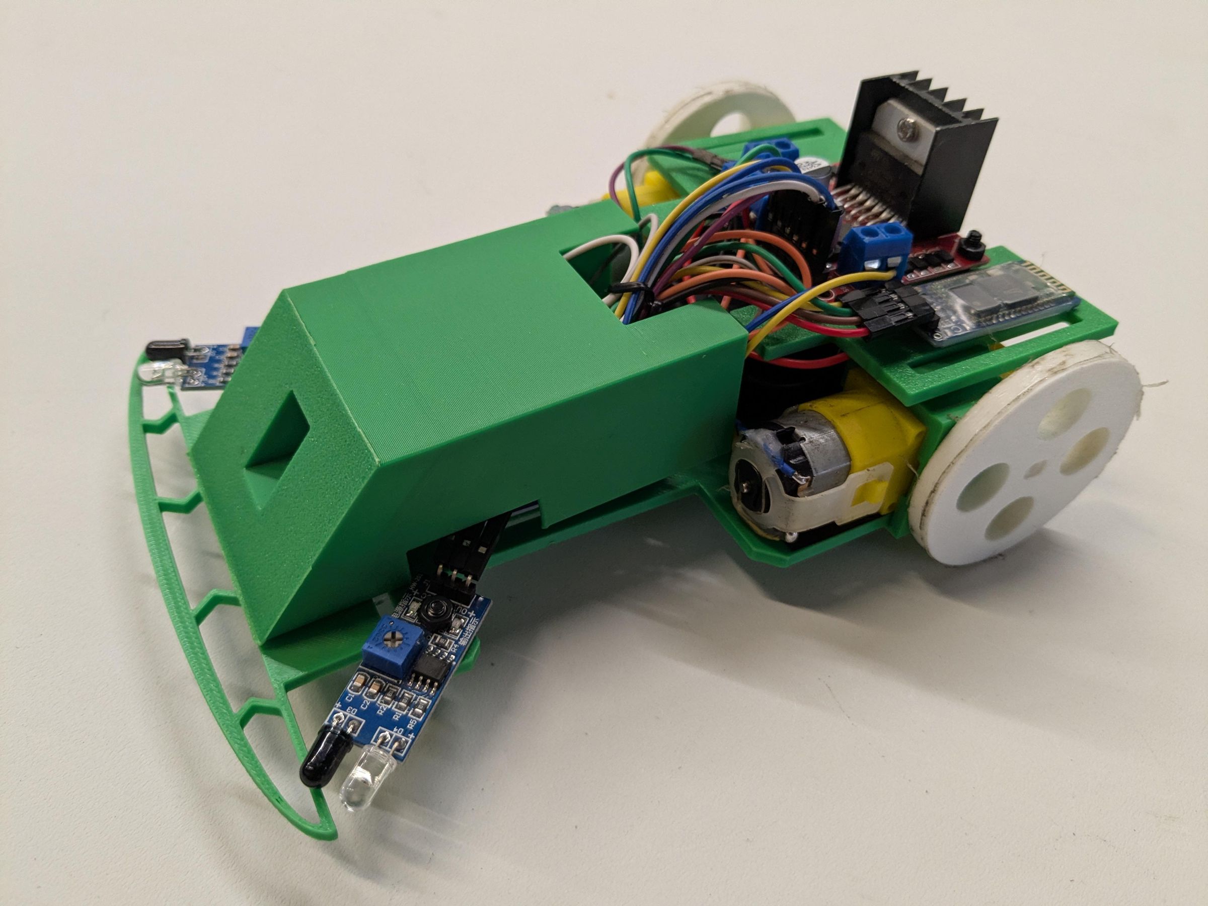
Arduino Neural Network Racer
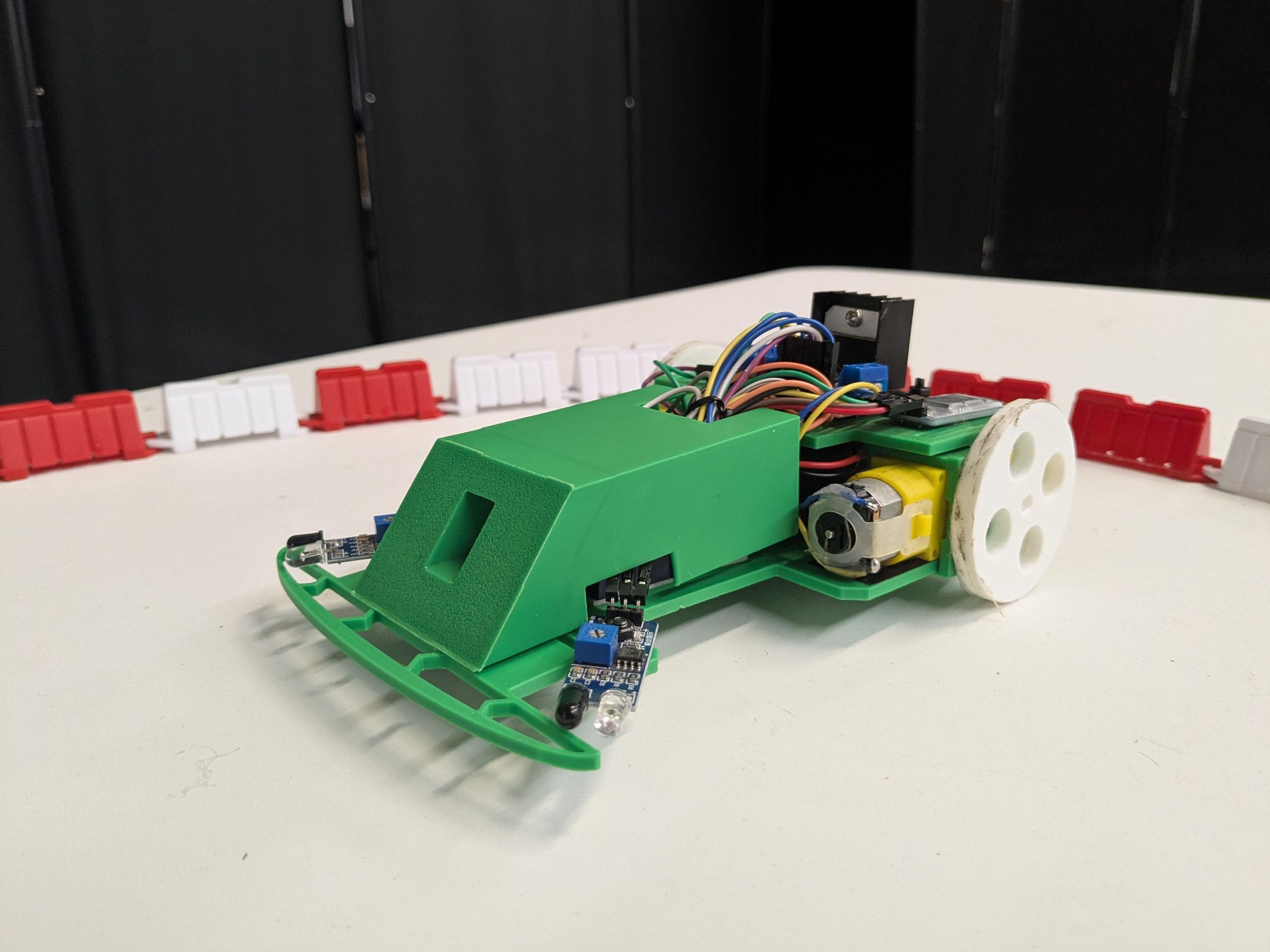
I’ve always been fascinated by autonomous vehicles. I'm currently studying software engineering so I can eventually work on full-size self-driving cars, but I figured—why wait? I decided to dive in and learn how to use a neural network to train an Arduino robot to navigate an RC racetrack.
Having taught robotics classes for years, I've noticed a common problem: too many robot kits are built, driven a few times, and then left to collect dust on a shelf. I wanted to design a project with replayability—one that encourages continuous learning and competition using readily available robotics parts.
To solve this, I turned my robot into a racecar. It challenges users to compete against one another, pushing them to train their neural networks and tune their robot car for the fastest possible lap times. This approach works so well that my robot car is currently being used at Tech Rockstar Academy in Monrovia, CA, to introduce youth to AI and robotics.
In this Instructable, I will show you everything you need to know to get your own mini neural network racecar on the track. We will cover:
- Step-by-step instructions to assemble the Arduino Neural Network Racer.
- How to train the neural network and tune the car for peak track performance.
- A guide on how to organize and host your own autonomous racing event.
- All the documentation, reference materials, and code I used to develop this project.
The Arduino Neural Network Racer was designed and developed by Joah Tang
Supplies
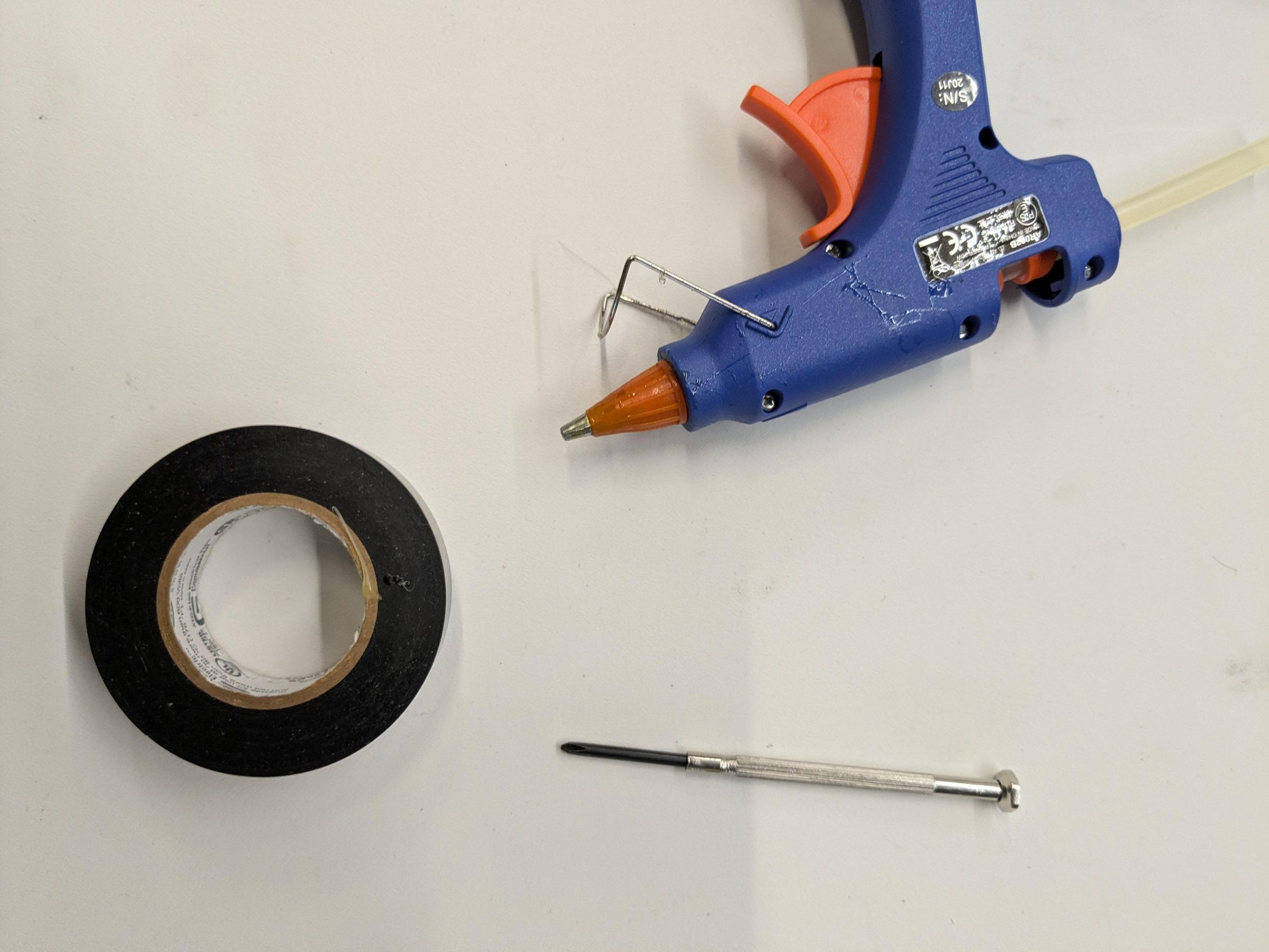
Tools:
- 3D printer (I use a Bambu A1)
- Hot glue gun
- Soldering Iron (optional you can order the motors pre-soldered with breadboard wires)
- Small Phillips head screwdriver
- Plastic nippers/ scissors /wire strippers
- Arduino IDE
- Computer/laptop
*Materials:
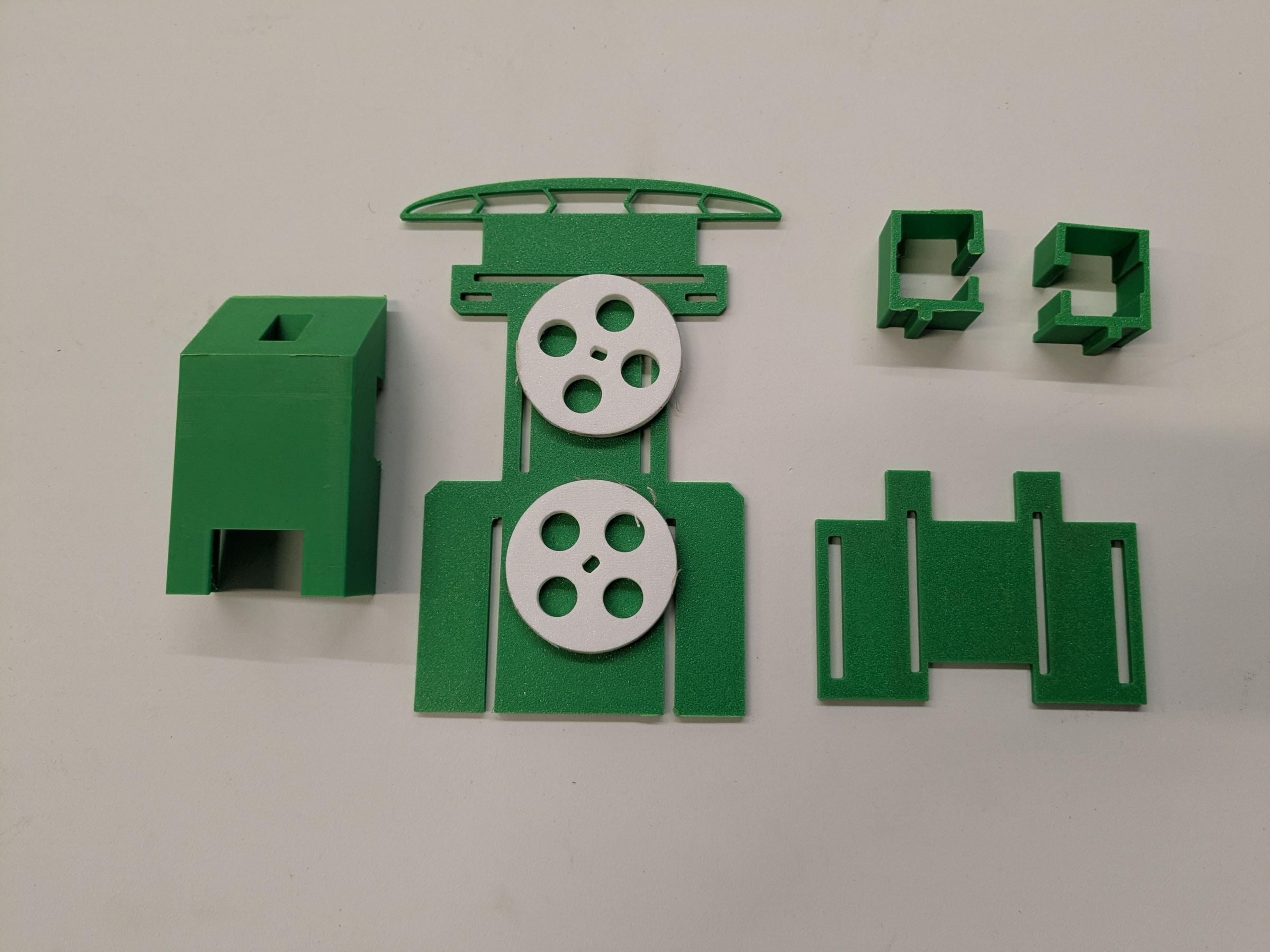
- 3D printed Arduino Neural Network Racer(The files are free and opensource on Tinkercad)
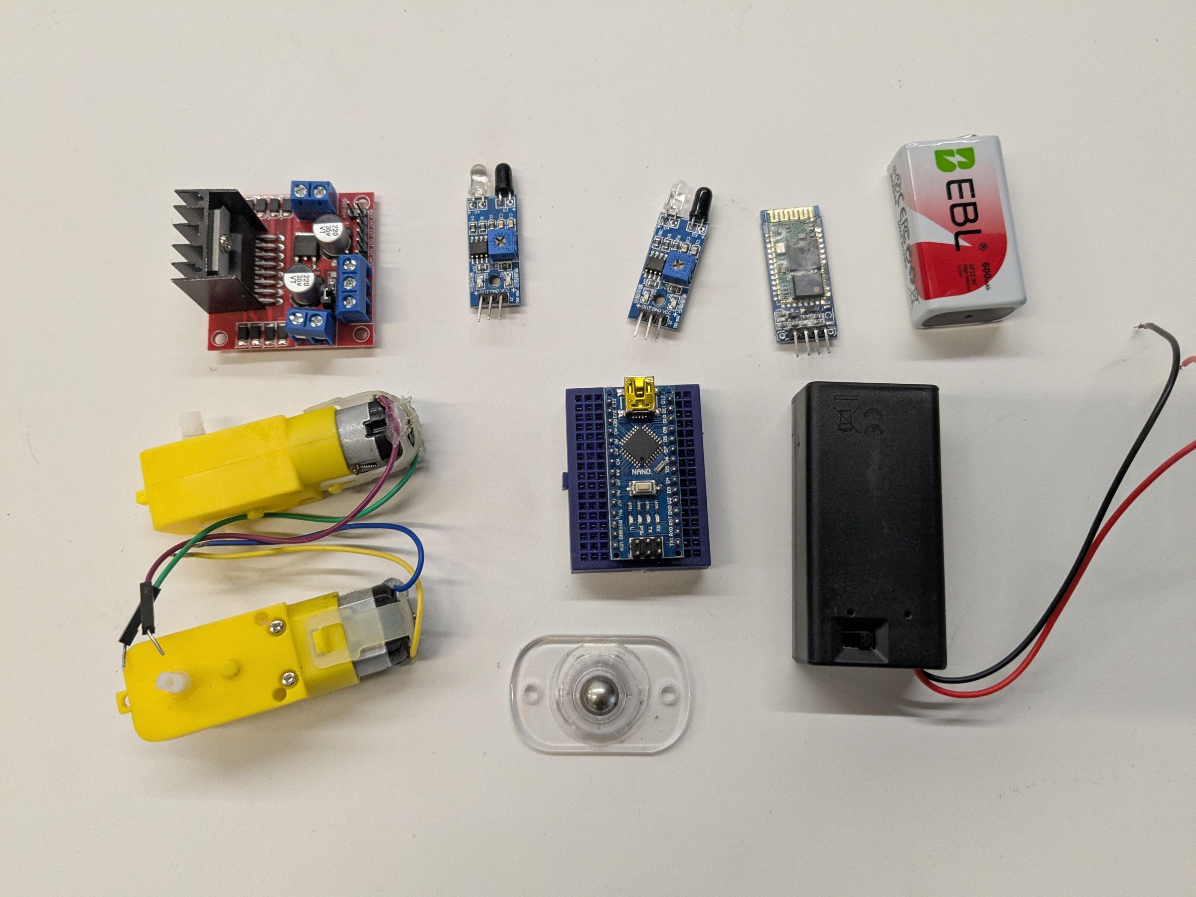
- 2x TTMotors with Gearbox
- 1x L298n Motor Driver
- 1x Arduino Nano with USB Cable
- 2x IR Sensors
- 1x Mini breadboard
- Variety pack of Male to Female Wires
- 1x Hc-06 Bluetooth Module
- 1x 9V Battery Box with Switch
- 1x Caster Ball
- Variety pack of M3 Screws and nuts
- Rechargeable 9v battery with charger
- Electric Tape
- Small zip tie or bread tie
*You will notice the links go to listing with more parts then needed. This is due to Amazon not selling single parts. The list above can be used to make two Arduino Neural Network Racers.
3D Print
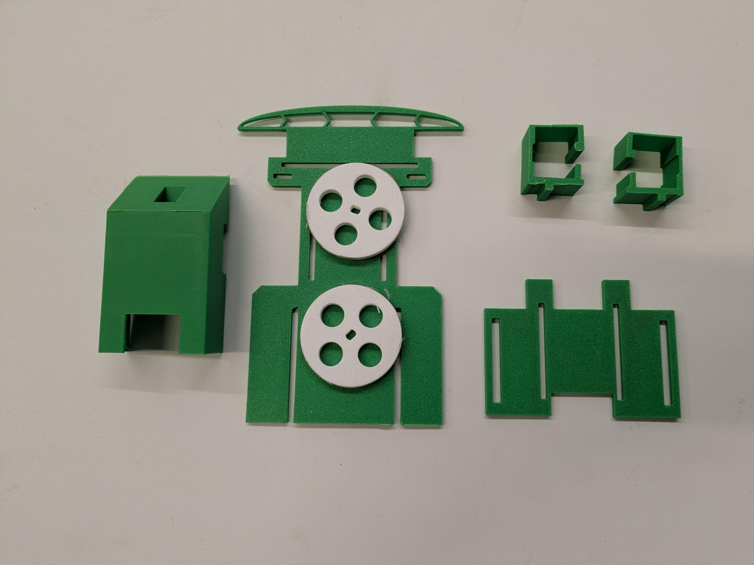
I used a Bambu A1 to print my robot. Most printers should be able to print this kit with it being mostly basic shapes. Here are my suggested settings,
- 15% infill
- Tree supports, this is used for the cowl that covers the Arduino Nano at the front of the robot (see picture).
- PLA
- Brim outer.
Attach Parts
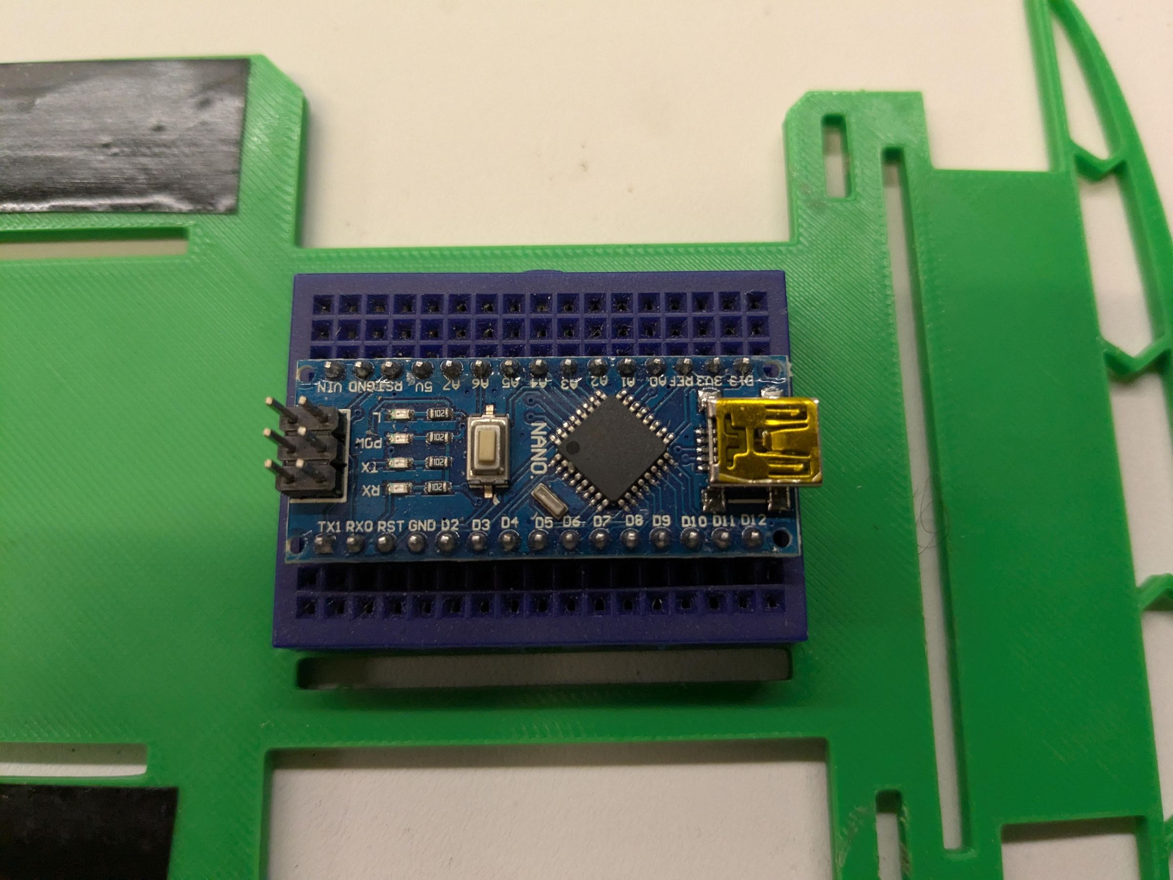
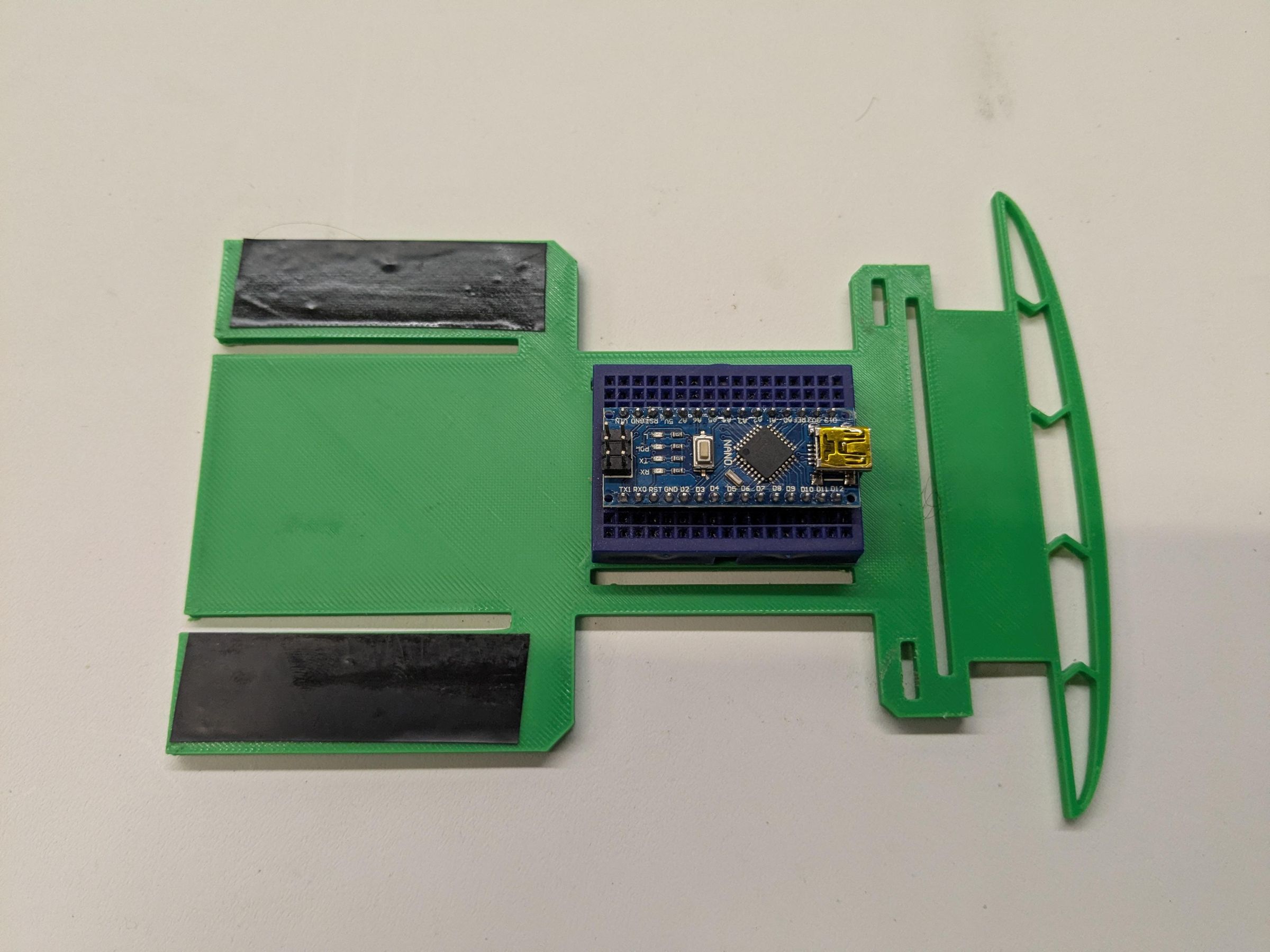
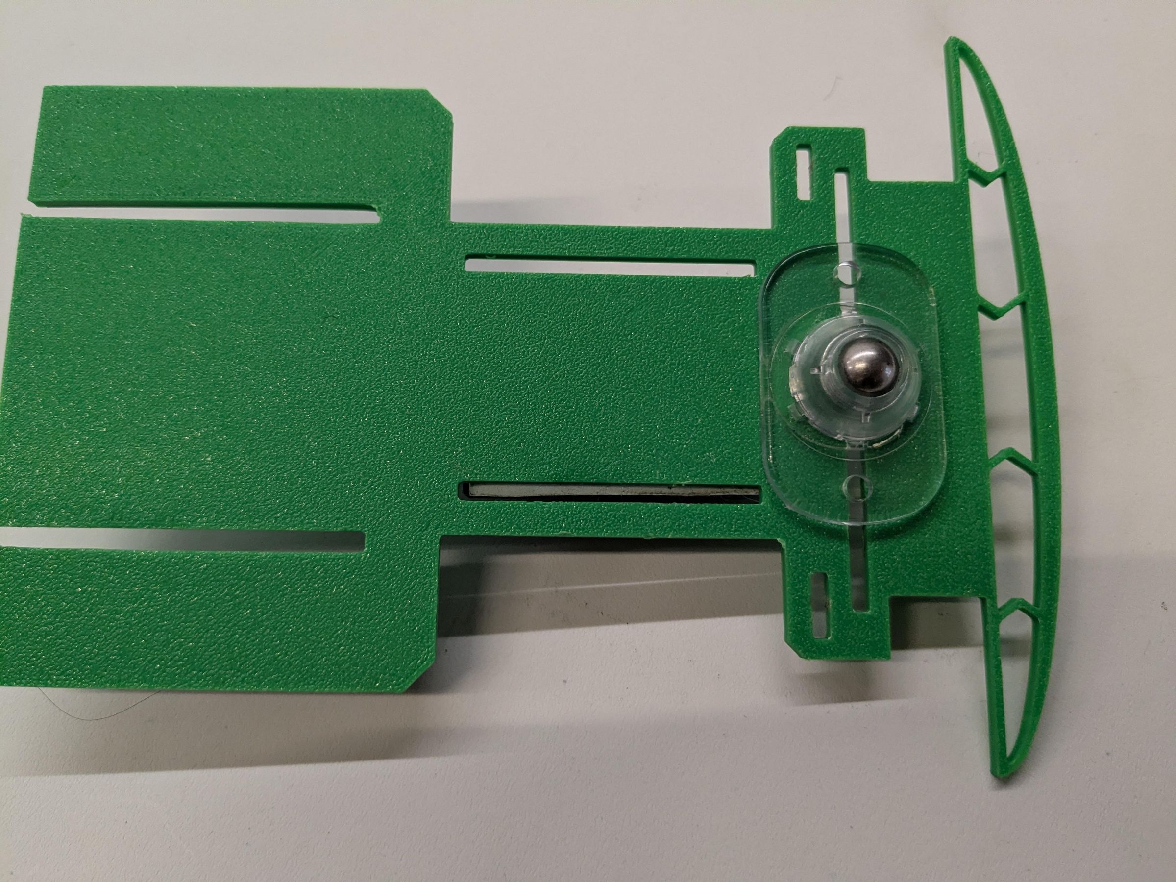
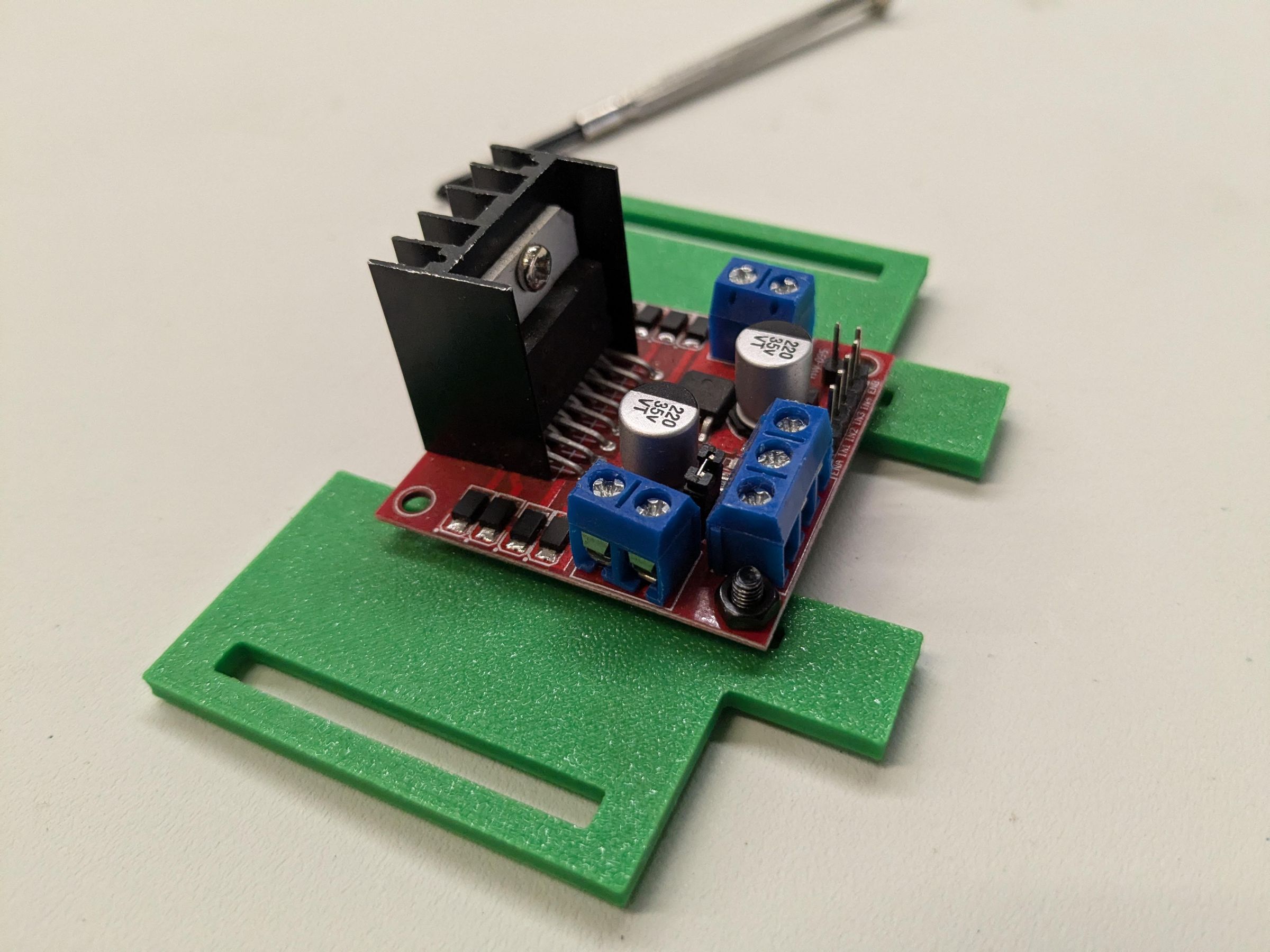
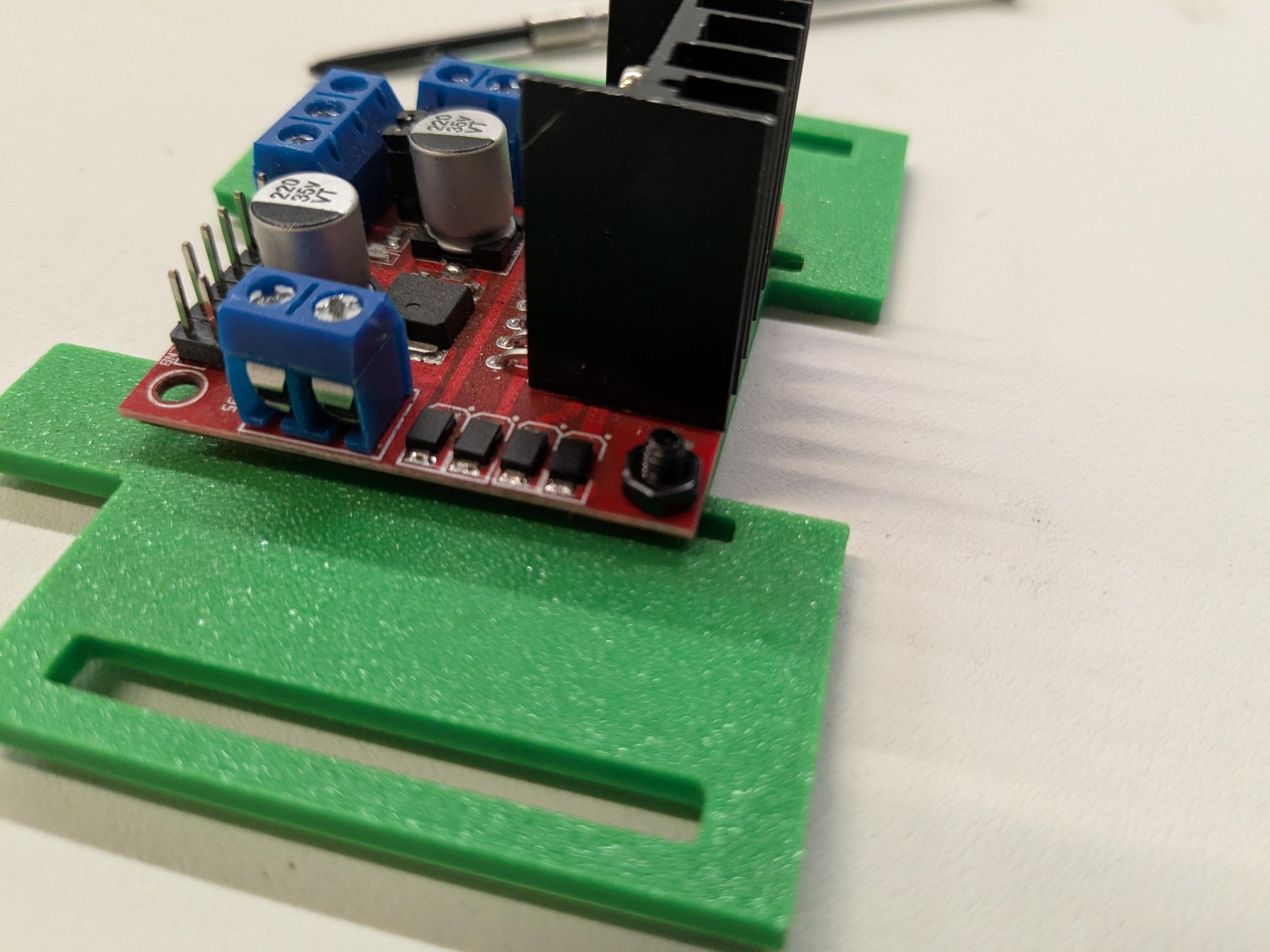
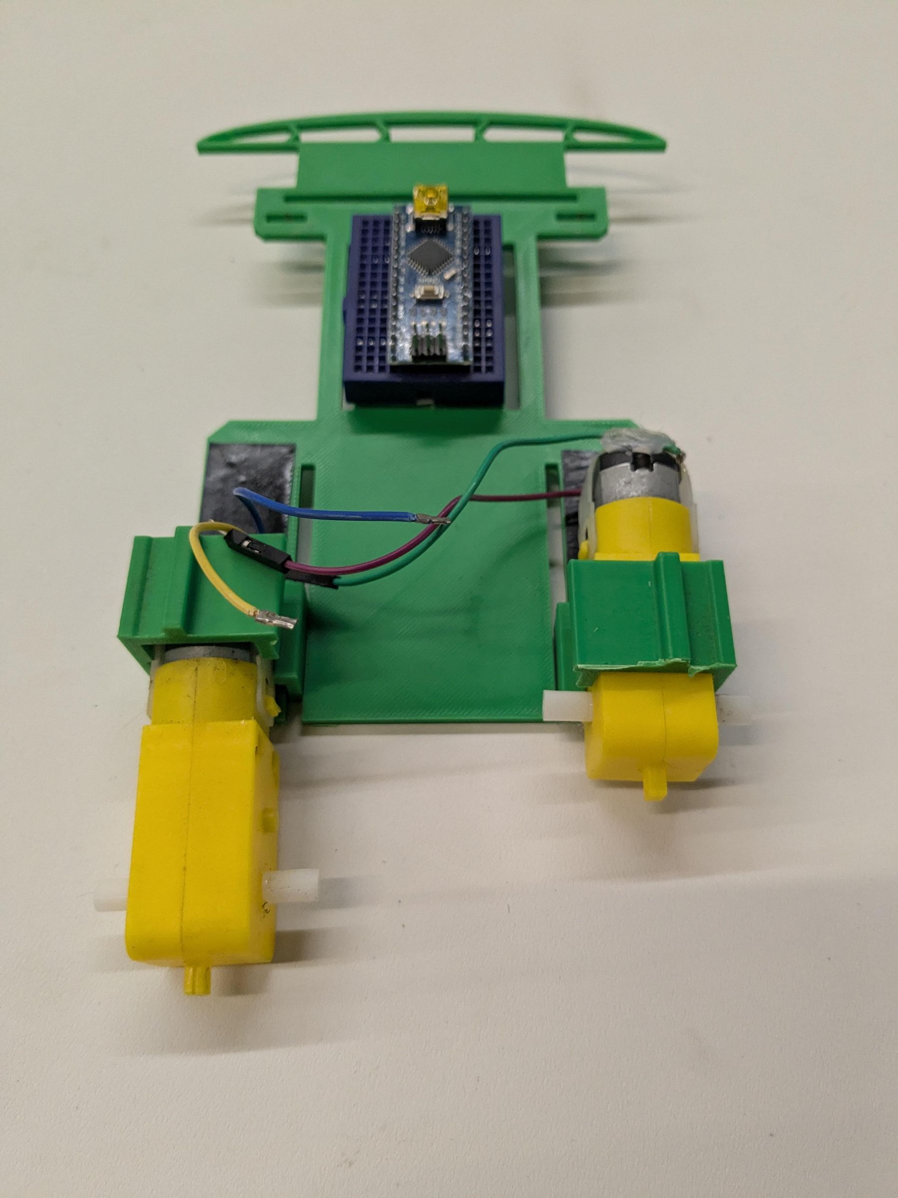
In this step we will attach the major parts to the chassis.
Take the mini breadboard and press the Arduino Nano into it leaving at least two rows of inputs on the side with the D Pins on the Arduino Nano. See the first picture for an example. You can click on the box drawn on the picture to get further details.
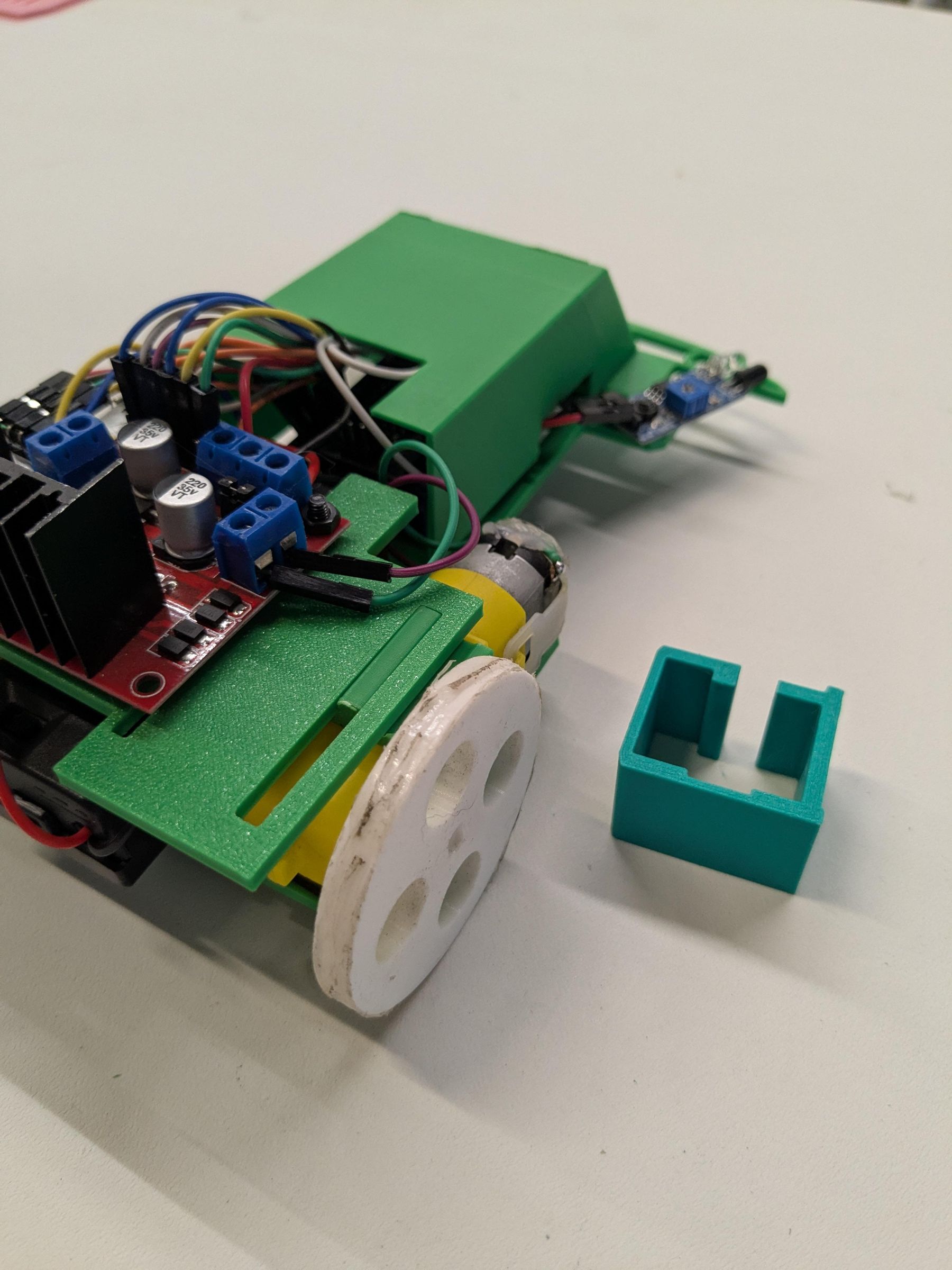
Once the Arduino Nano is seated in the mini breadboard use the included adhesive to attach it to the front of the chassis shown in the second picture. Also, apply a strip of electrical tape to the rear of chassis along the inputs for the motor clips. This is used to help the motors from moving around while the robot is driving. The motors are left loose so you can adjust the weight distribution of the robot to tune it's performance. The further back the motors sit the better it will go in a straight line. The closer the motors are to the center of the robot the better the it will take corners.
Rotate the chassis upside down and adhere the caster ball with the provided adhesive to the center and front of the chassis. You can align the screw holes on the caster to the slit as seen in the third picture for best alignment.
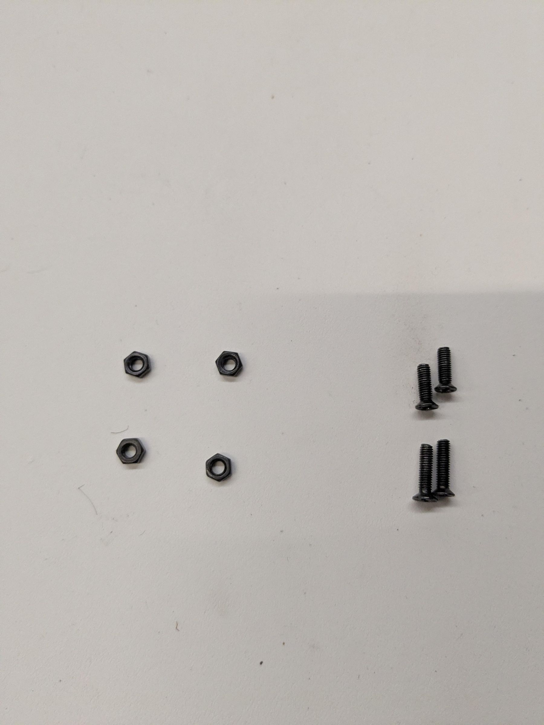
Take the Motor driver mount and attach the L298n motor driver to it using two M3 12mm screws and nuts. The screws should come up from the bottom of the motor driver holder and L298n. Reference the fourth and fifth picture.
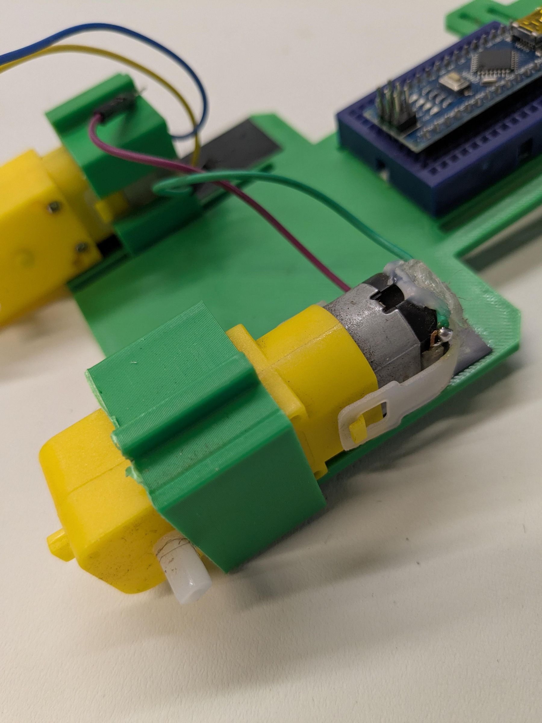
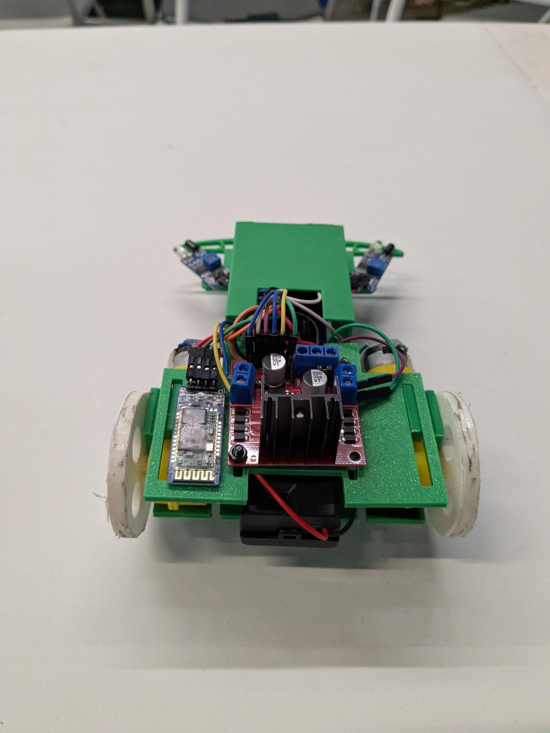
Finally, take the motors and clips. Slide the motor through each clip so the pads where the wires are soldered on point to the out side of the car. Please see the last to pictures for orientation. Once the motors are in the clips slide the motors over the top of the chassis.
Power Distribution
In this step we will put together the power distribution circuit.
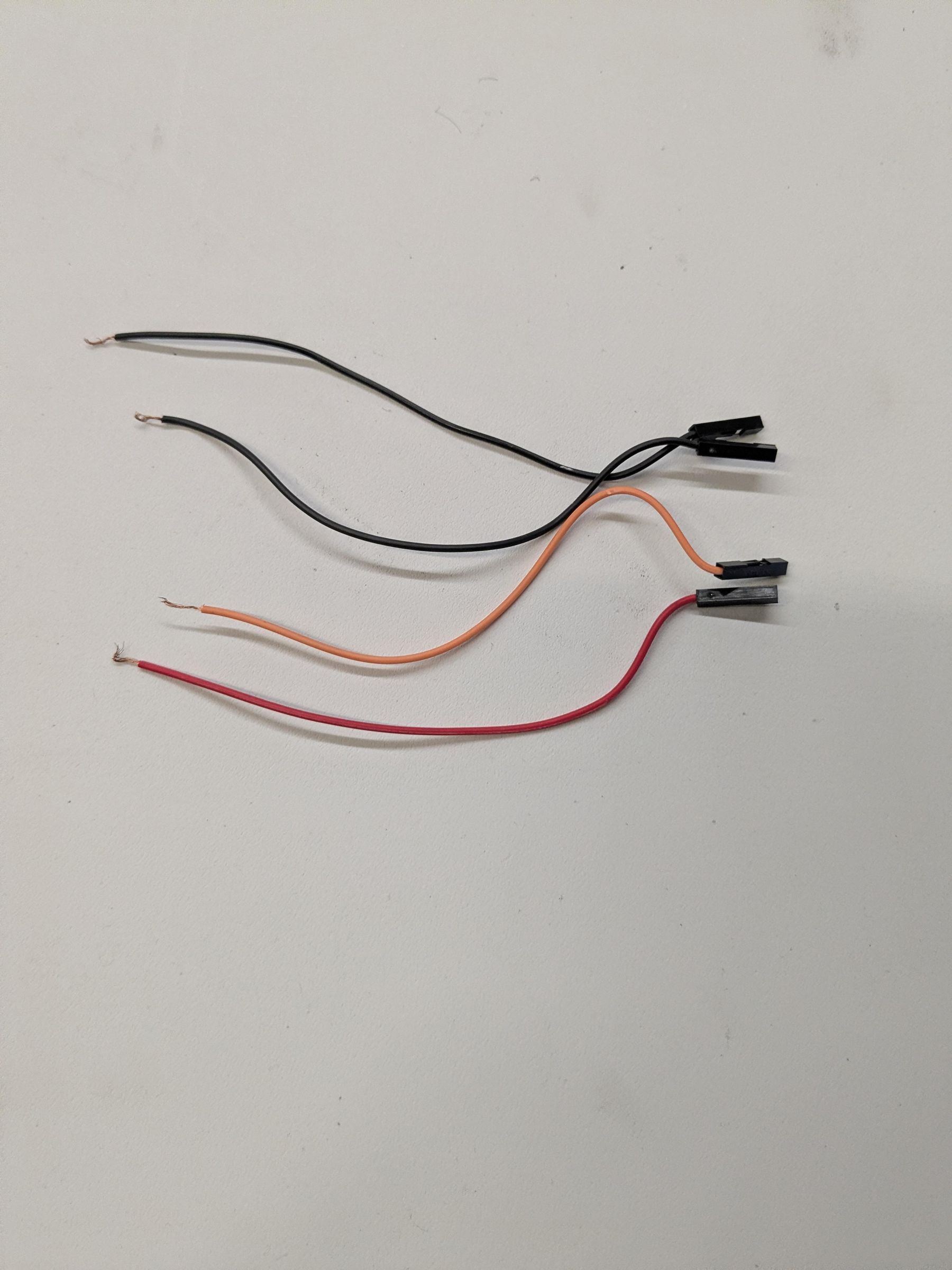
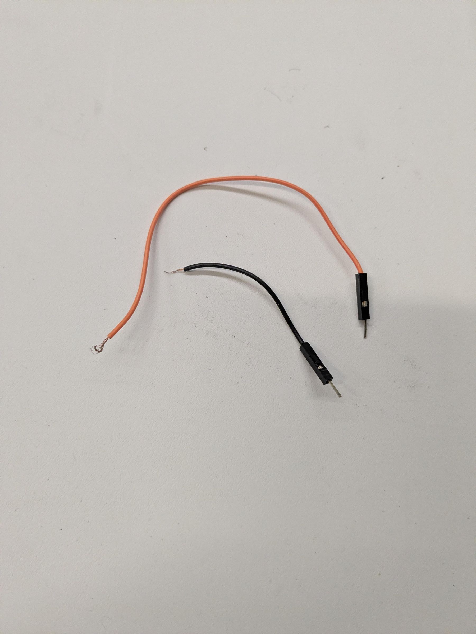
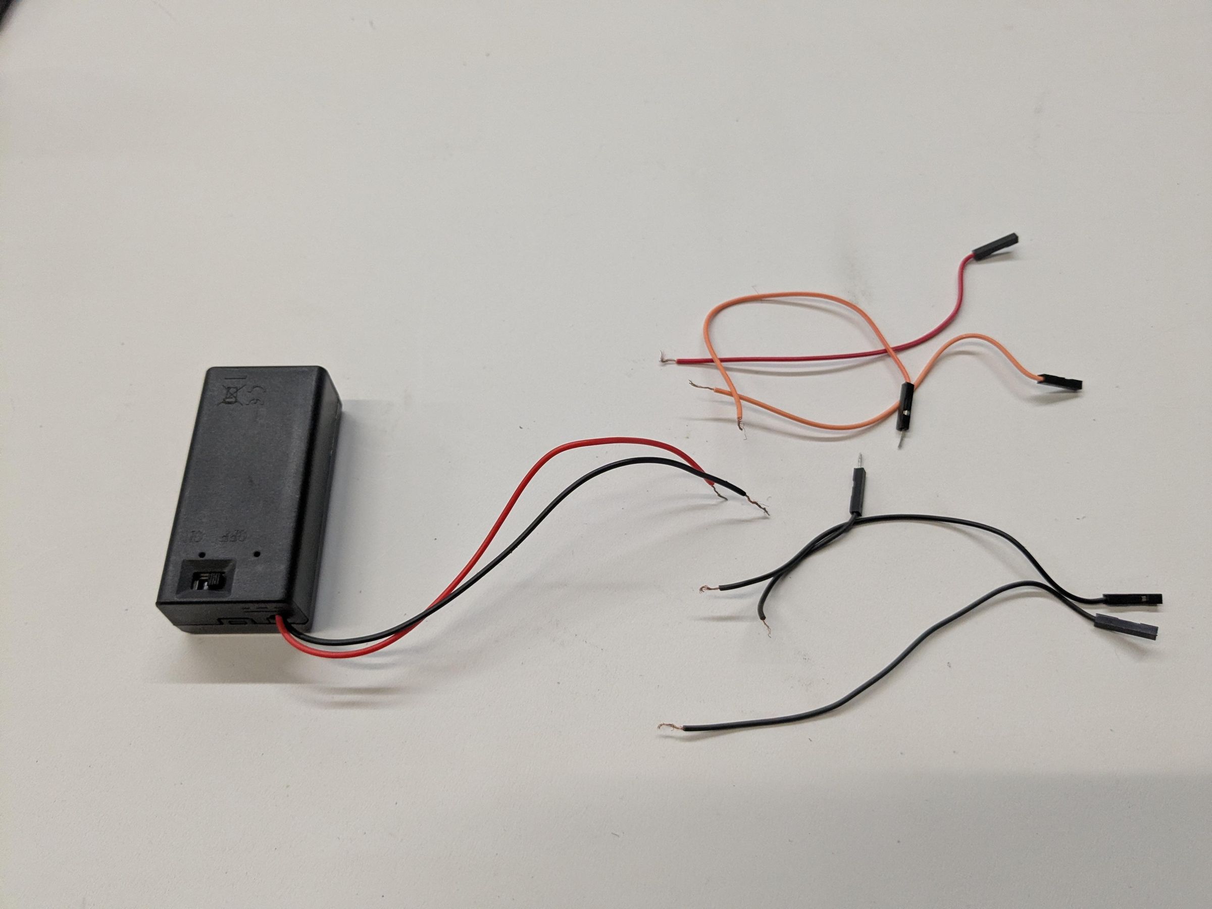
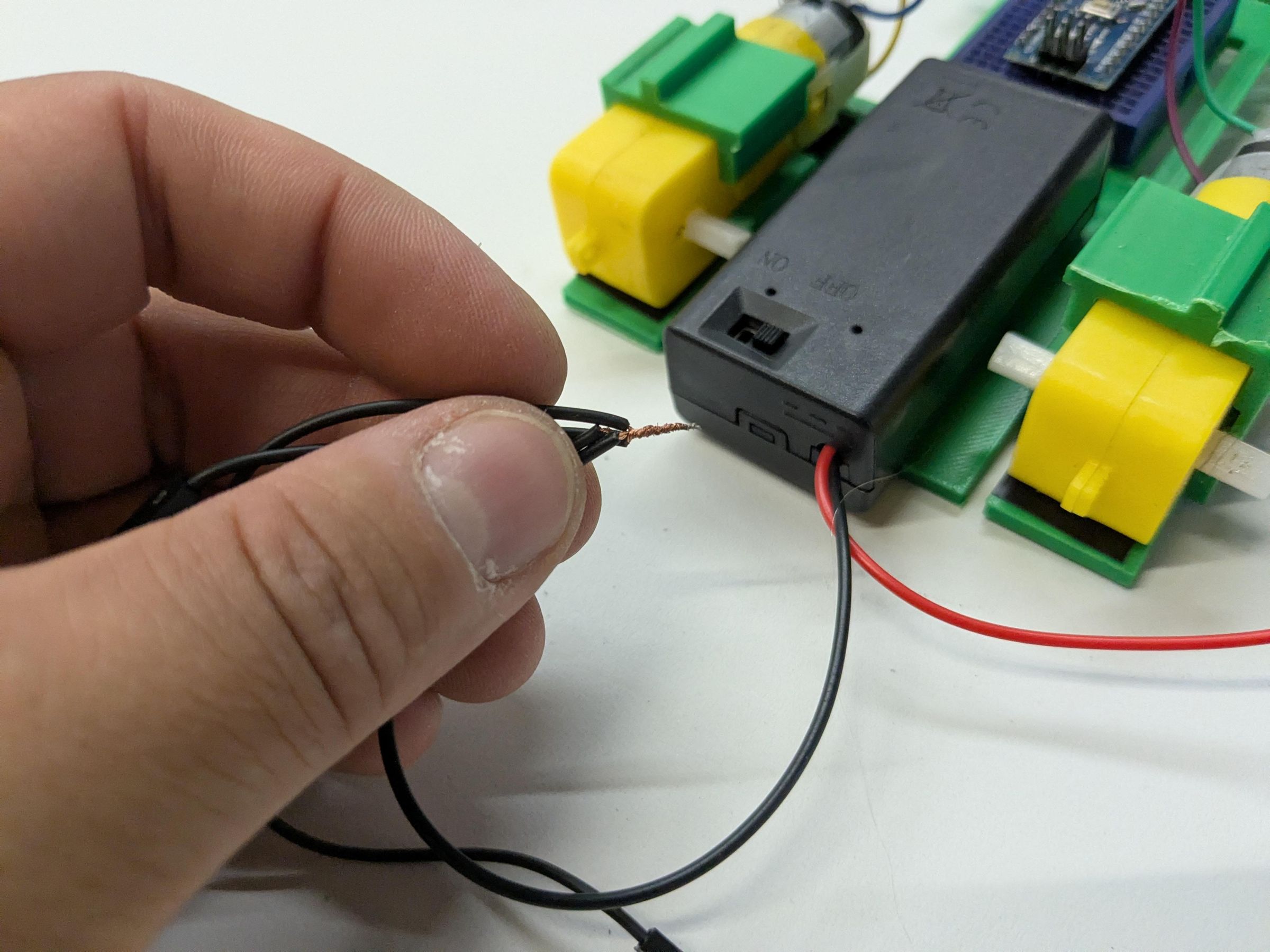
Take the 9v battery box and strip both the red and black wire. Take two orange and two brown bread board wires. Cut them in half. Take two of the cut brown wires with female adapters and strip the cut ends. Do the same for two orange wires with female adapters. Take the orange and a brown wire halves with male adapters and strip the end cut ends. See first picture for details.
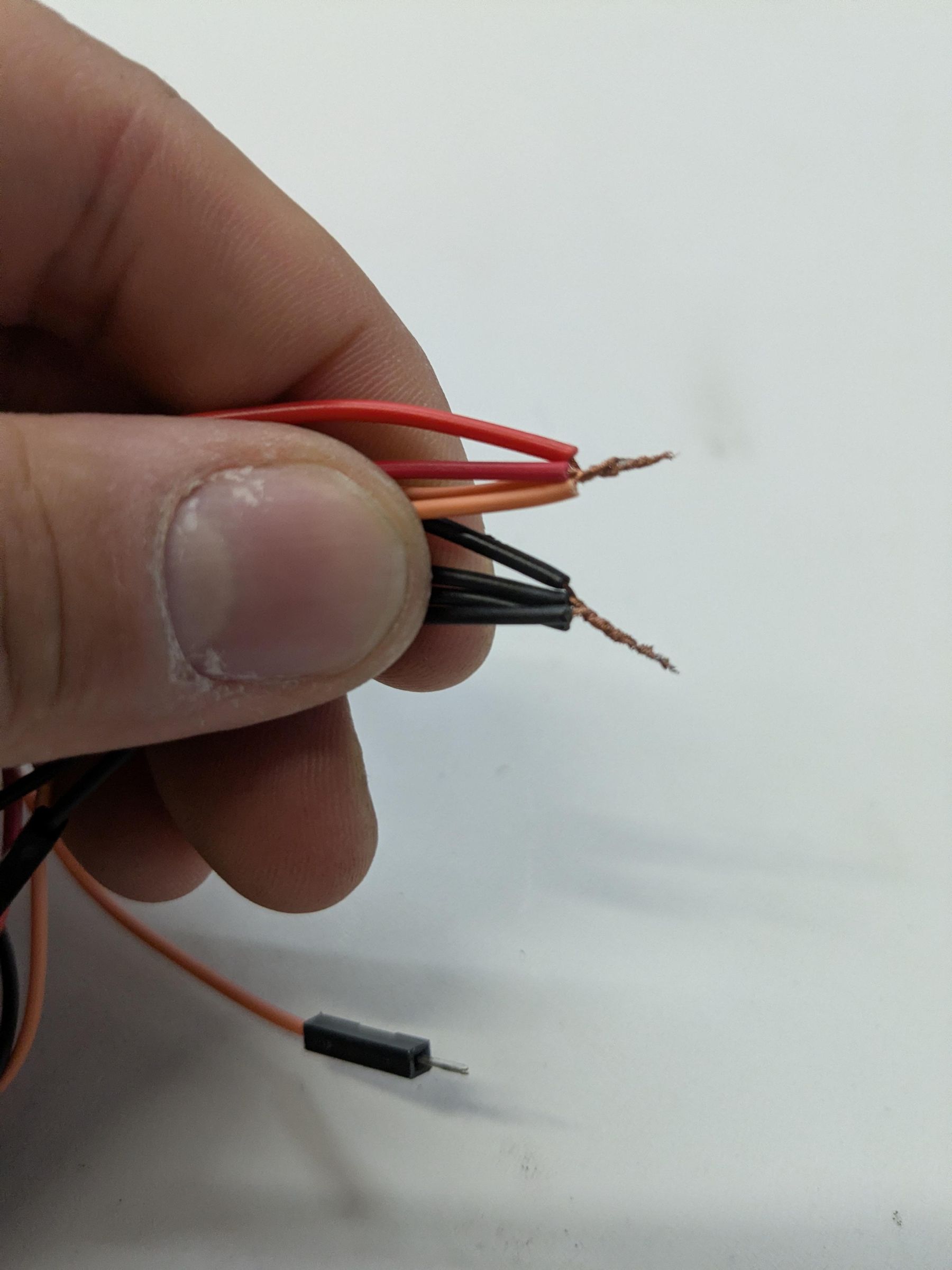
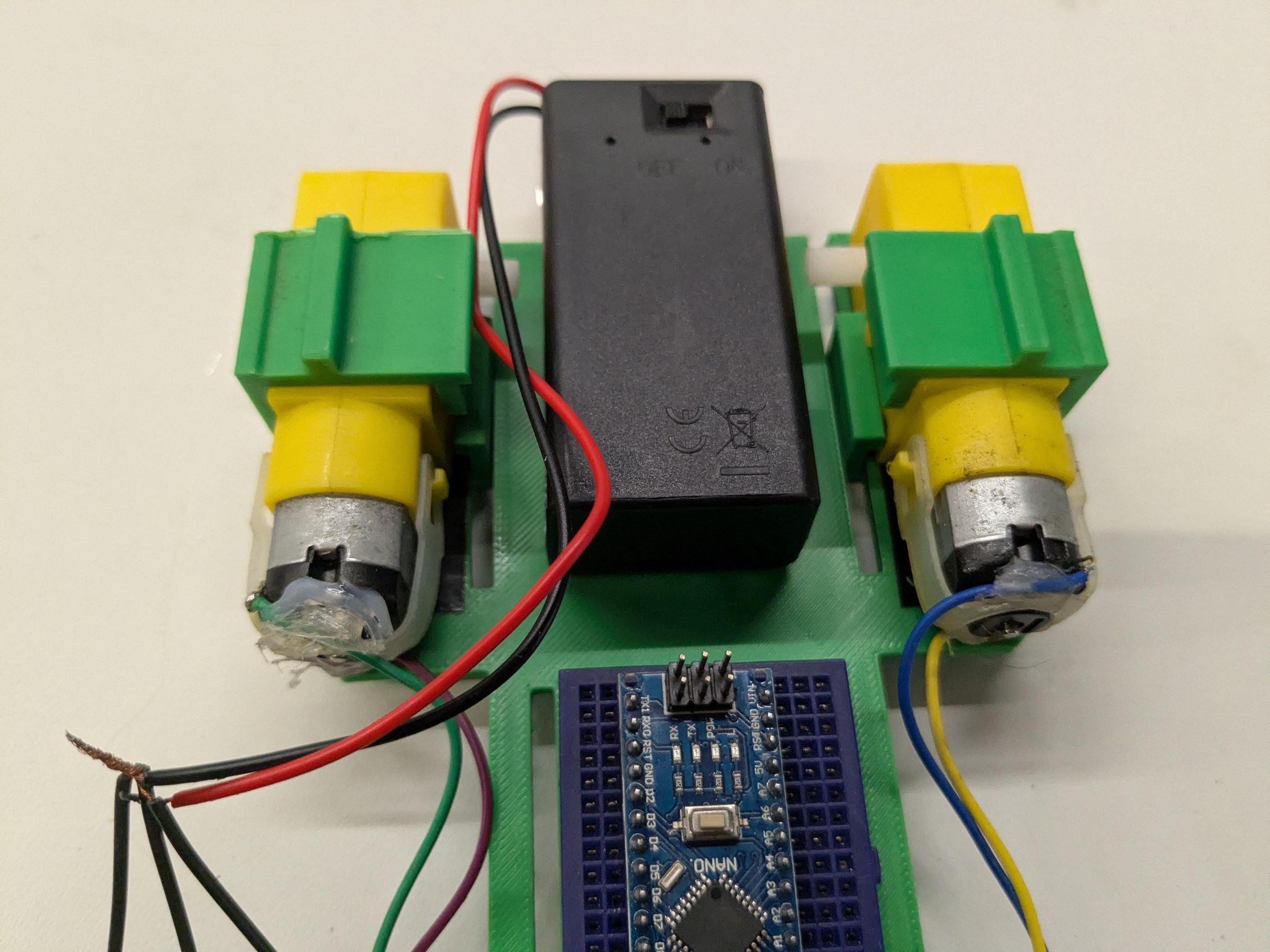
Twist all the cut ends of the black breadboard wire together. Do the same for the cut orange breadboard wires. See picture 2.
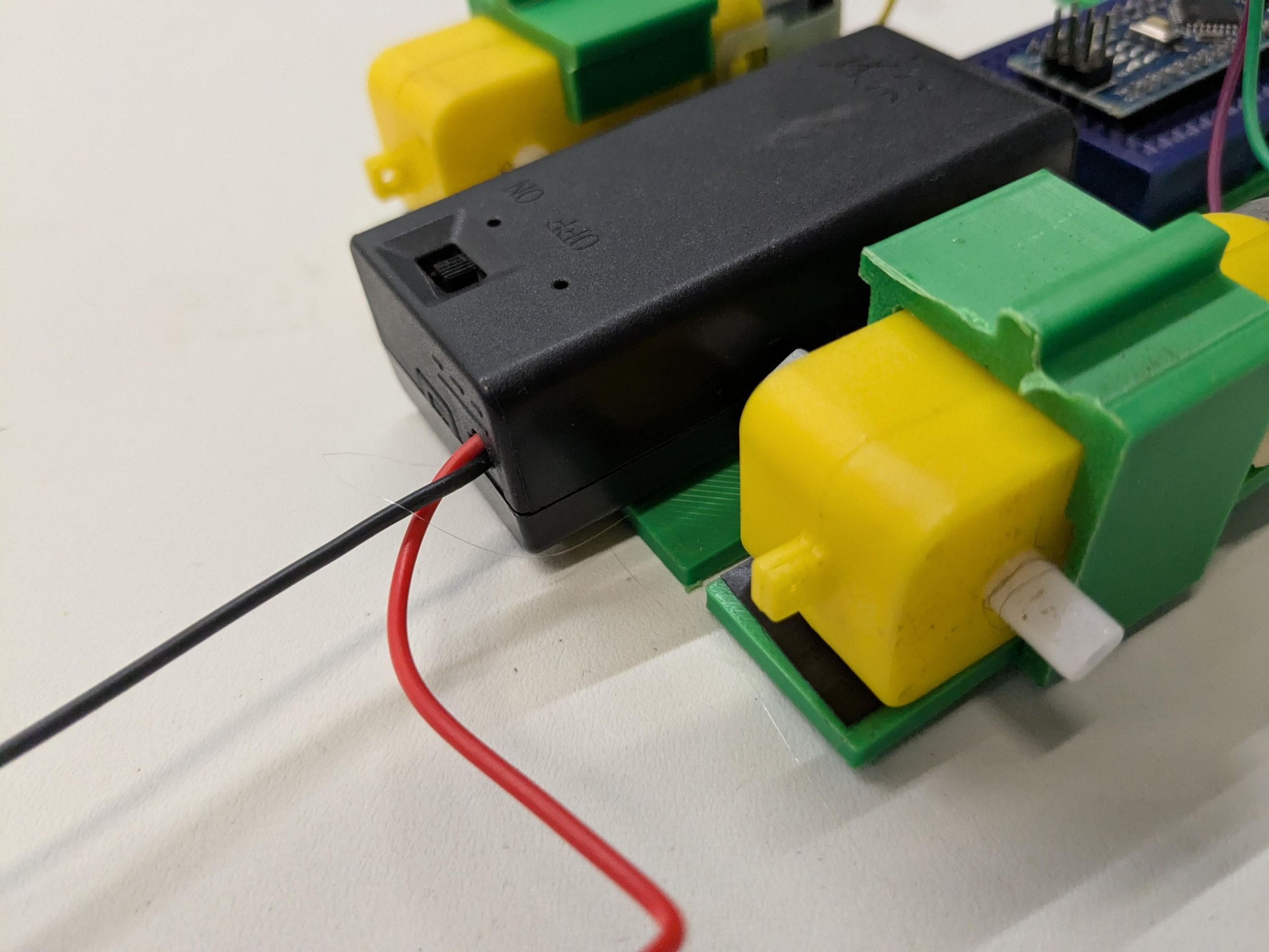
Hot glue the battery box to the rear of the chassis with the switch side slightly over and the box centered. See the third picture for alignment.
Take the twisted together black wires and twist the black wire from the battery box to them(picture 4).
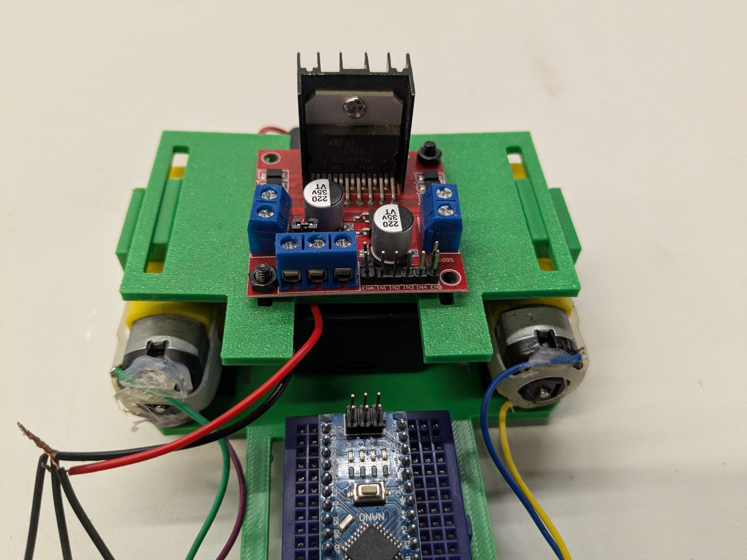
Route the battery box wire to the front of the chassis (picture 5).
Attach motor driver mount to the motor clips at the rear of the chassis see the sixth picture for orientation.
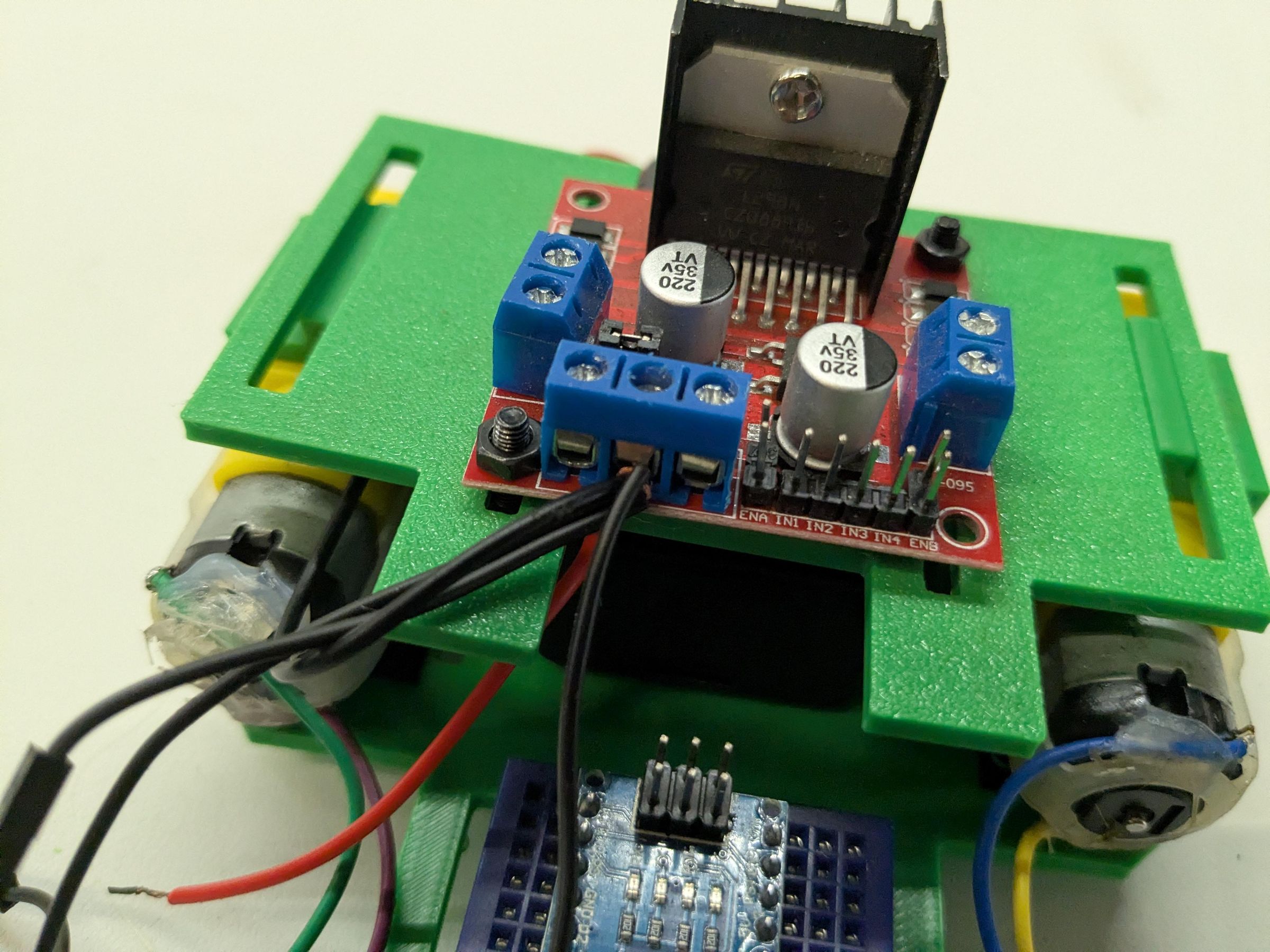
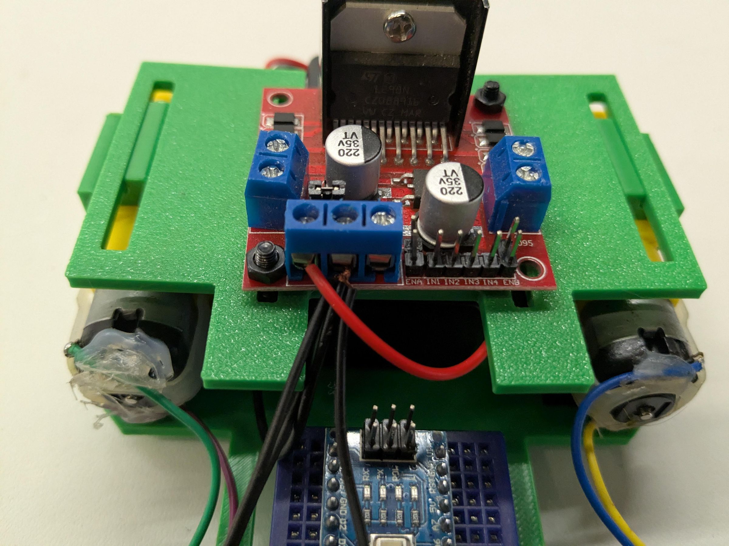
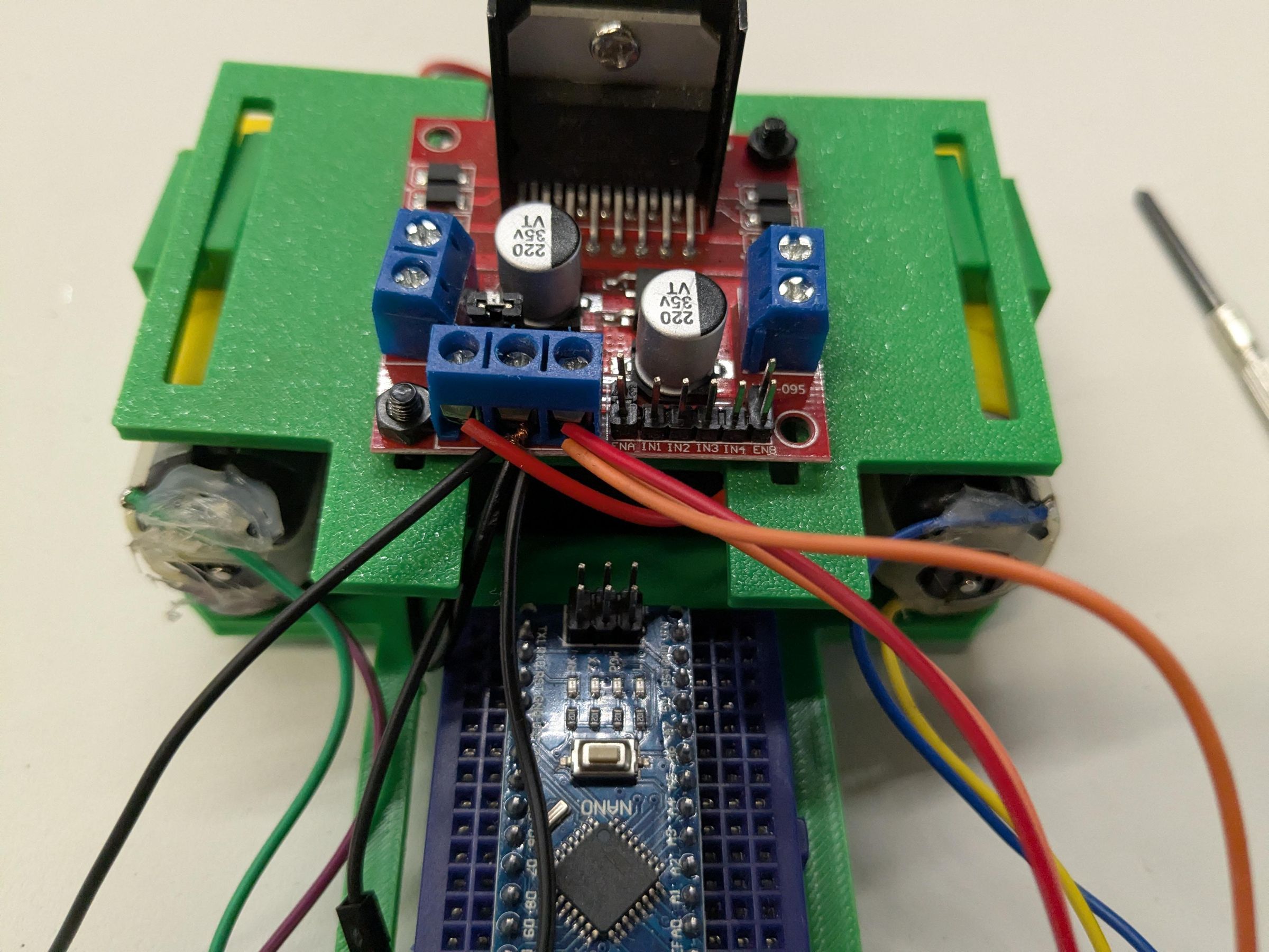
Loosen the GND screw down port on the L298n with a screwdriver. Insert the twisted together end of all the black wires and tighten down the GND port(picture 7).
Loosen the 12v port on the L298n with a screwdriver and insert the stripped end of the single red wire coming from the battery box, then tighten down (picture 8).
Finally, loosen the 5V port on the L298n and insert the twisted end of the orange wires and then tighten down (picture 9).
Add Sensors and Bluetooth to the Circuit.
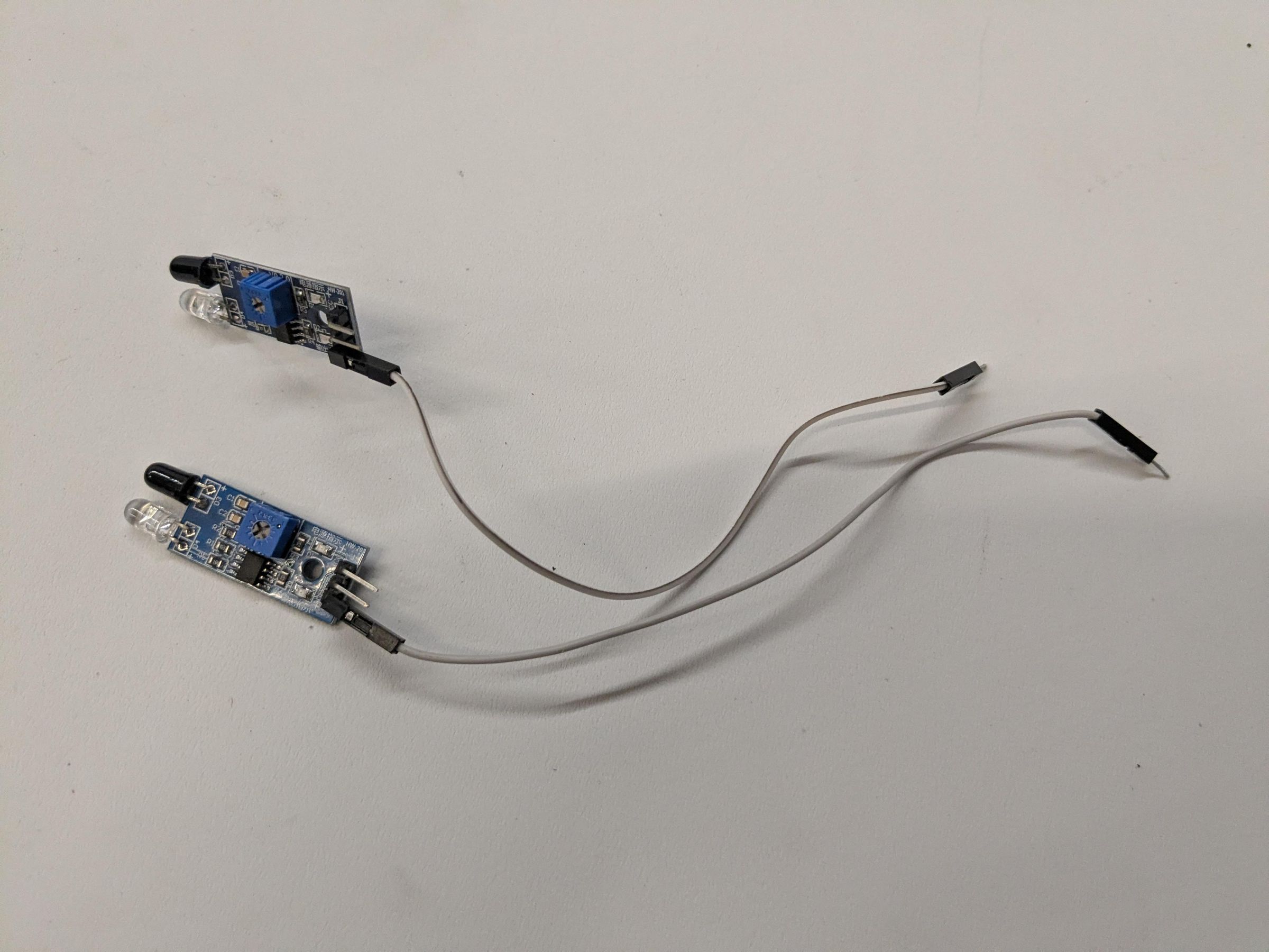
Take a white and grey female to male wire. Attach the white wire to OUT pin on an IR sensor. Do the same for the grey wire (picture 1).
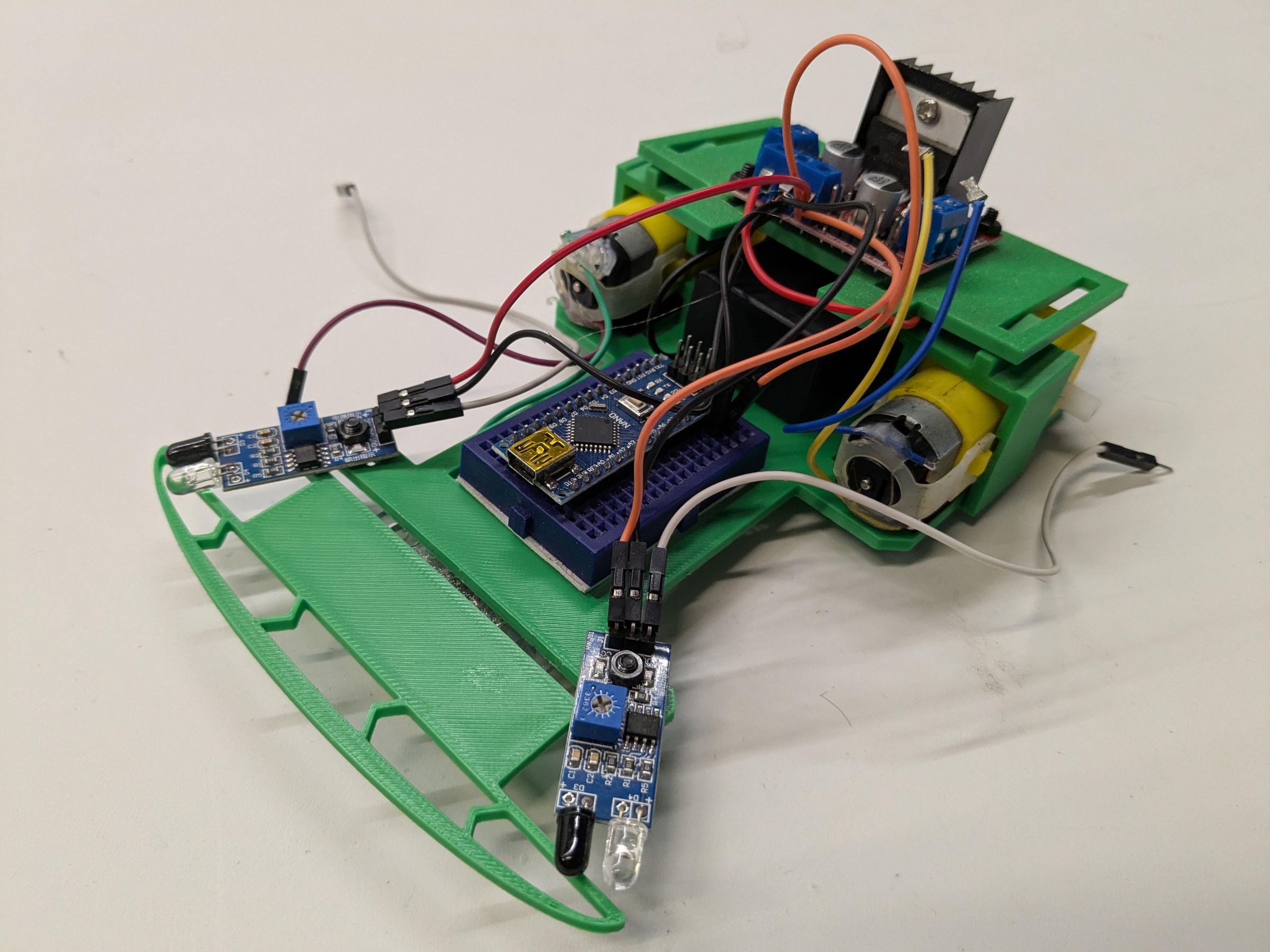
Using two M3 10mm screws and nuts attach the sensors according to the second picture, please click on the boxes drawn around each one to see which side the white wired sensor and the grey wired sensor go on.
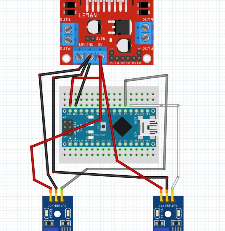
Using the third picture as a guide attach the following components together:
- L298n Orange wire female end from the 5v port goes to the IR sensor with the white wire VCC port.
- L298n Orange wire female end from the 5v port goes to the IR sensor with the grey wire VCC port.
- L298n Orange wire male end goes to the mini breadboard input next to the Arduino Nano 5v pin
- L298n Black wire female end goes to the IR senor with the white wire GND pin.
- L298n Black wire female end goes to the IR senor with the grey wire GND pin.
- L298n Black wire with male end goes to the breadboard input next to the Arduino Nano GND pin.
- The White wire coming from the IR sensor goes to the mini breadboard input next to the Arduino Nano A0 pin.
- The Grey wire coming from the IR sensor goes to the mini breadboard input next to the Arduino Nano A1 pin.
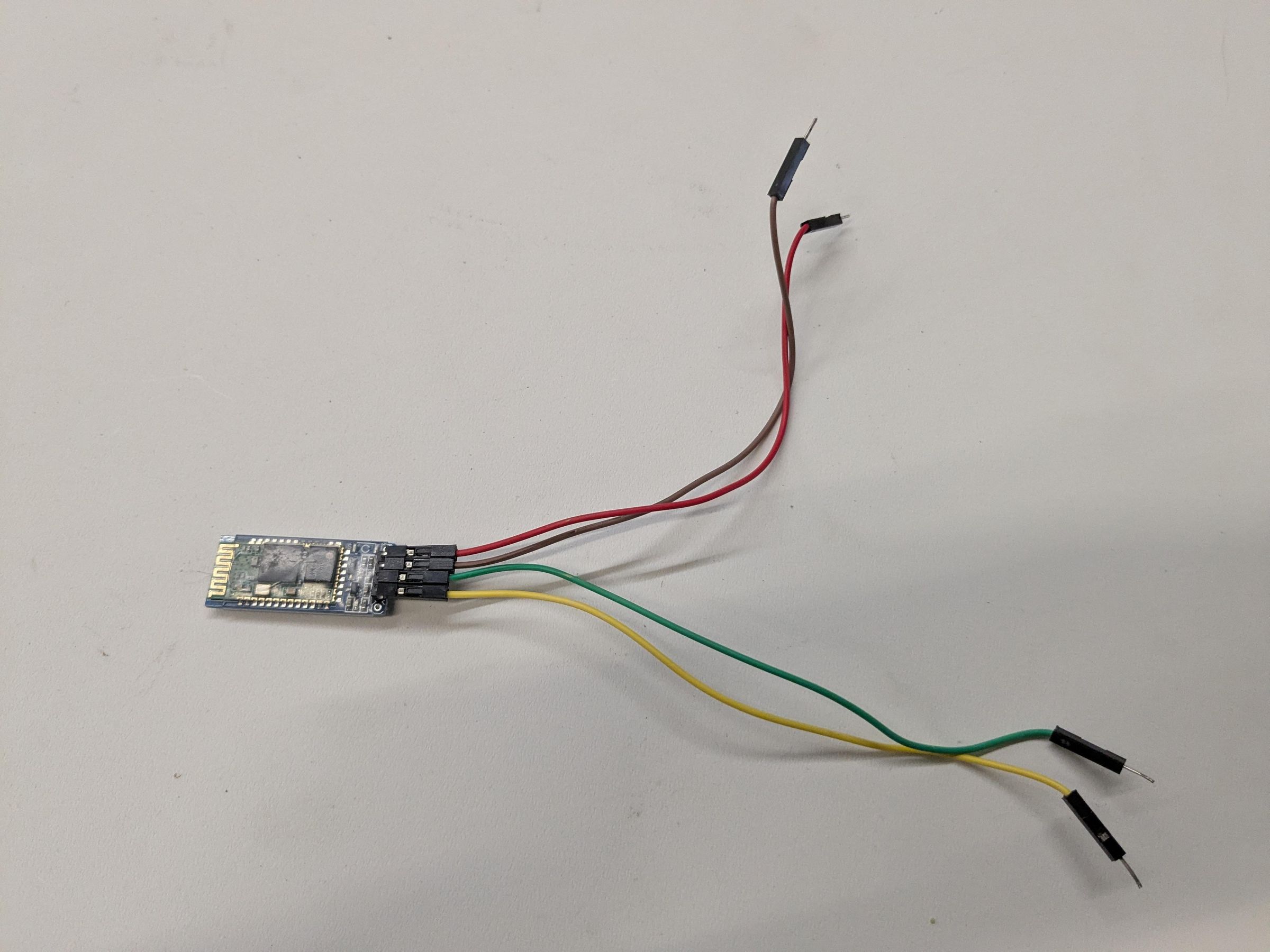
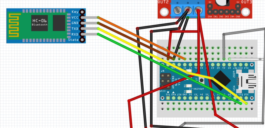
Gather an orange, brown, yellow, and green wire along with the HC-06 Bluetooth module. Make the following connection and use picture 4 and 5 as a guide:
- Take the female end of the Orange wire and connect it to the HC-06 VCC pin
- Use the male end of the Orange wire coming from the HC-06 and insert it into the mini breadboard next the Arduino Nano 5V pin.
- Take the female end of the Brown wire and connect it to the HC-06 GND pin
- Use the male end of the Brown wire coming from the HC-06 and insert it into the mini breadboard next the Arduino Nano GND pin.
- Take the female end of the Green wire and connect it to the HC-06 RX pin
- Use the male end of the Green wire coming from the HC-06 and insert it into the mini breadboard next the Arduino Nano D11 pin.
- Take the female end of the Yellow wire and connect it to the HC-06 TX pin
- Use the male end of the Yellow wire coming from the HC-06 and insert it into the mini breadboard next the Arduino Nano D12 pin.
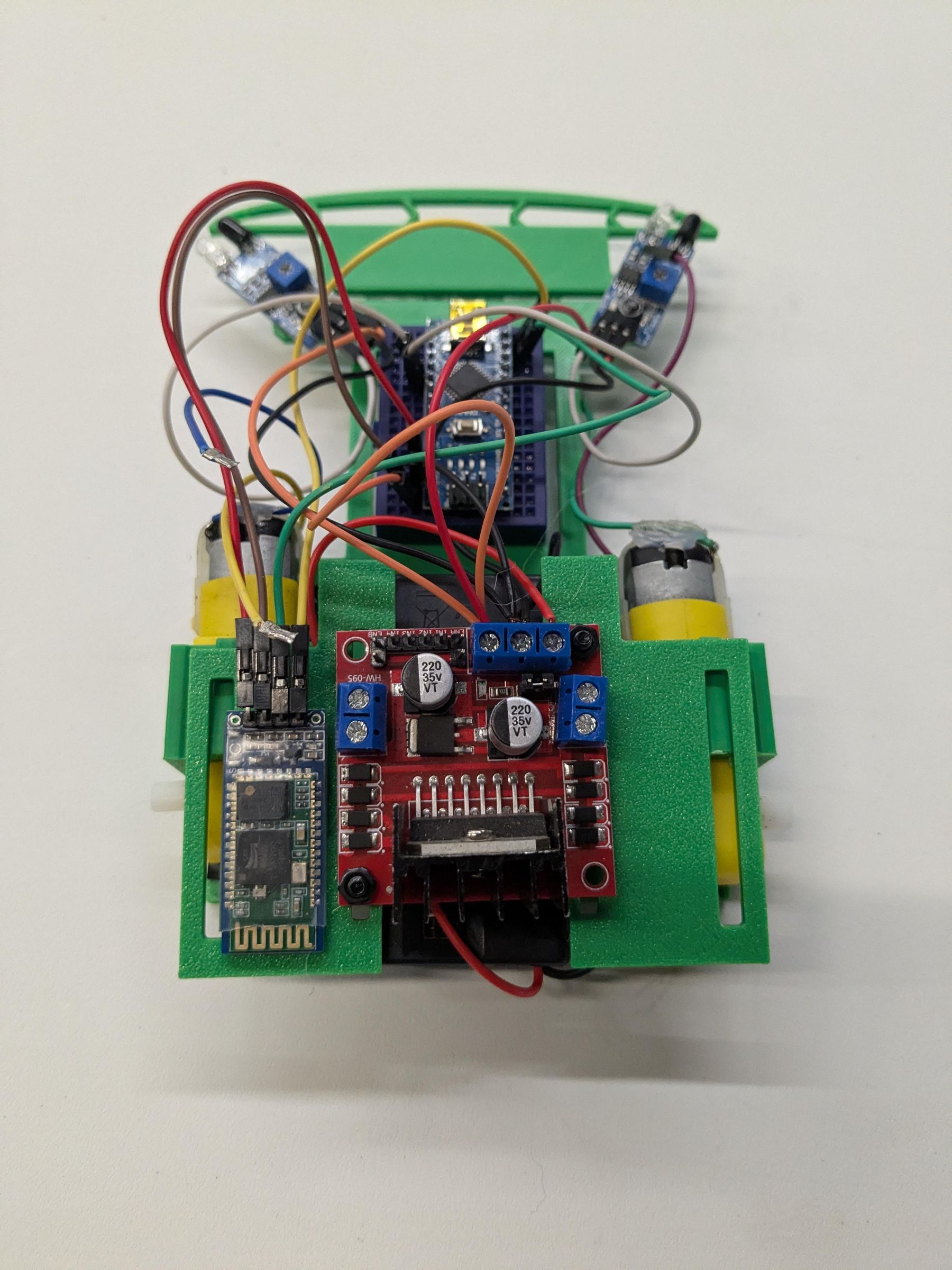
Take the HC-06 Bluetooth module and hot glue along side the L298n on the Motor Driver Mount (picture 6).
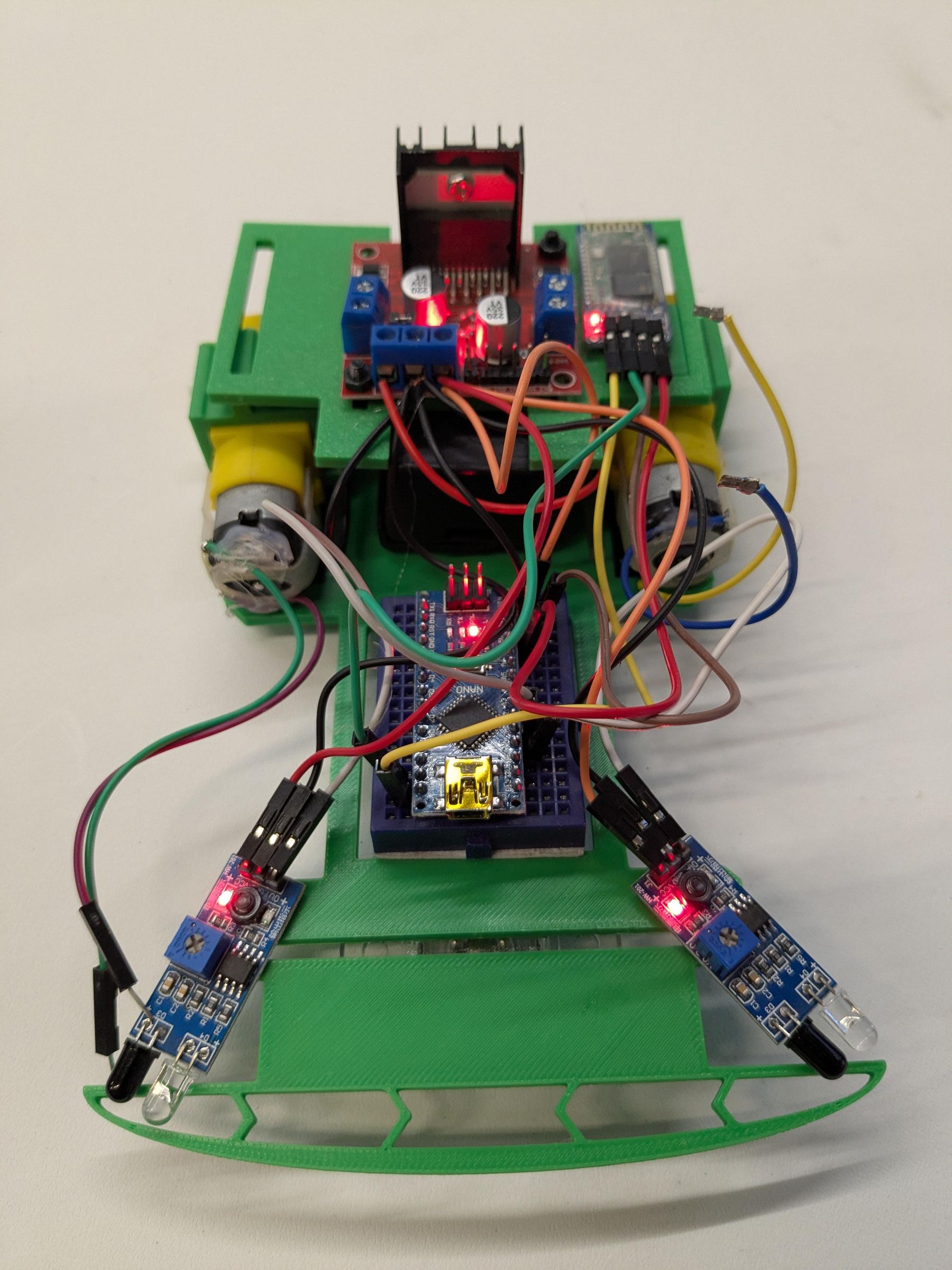
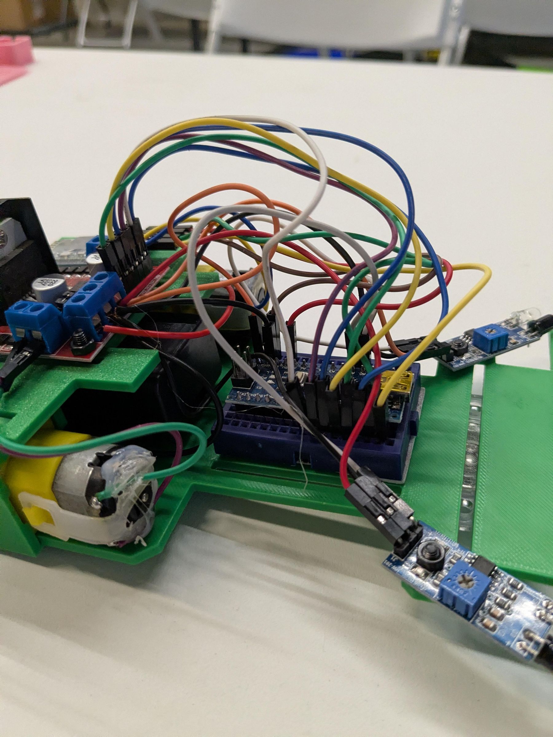
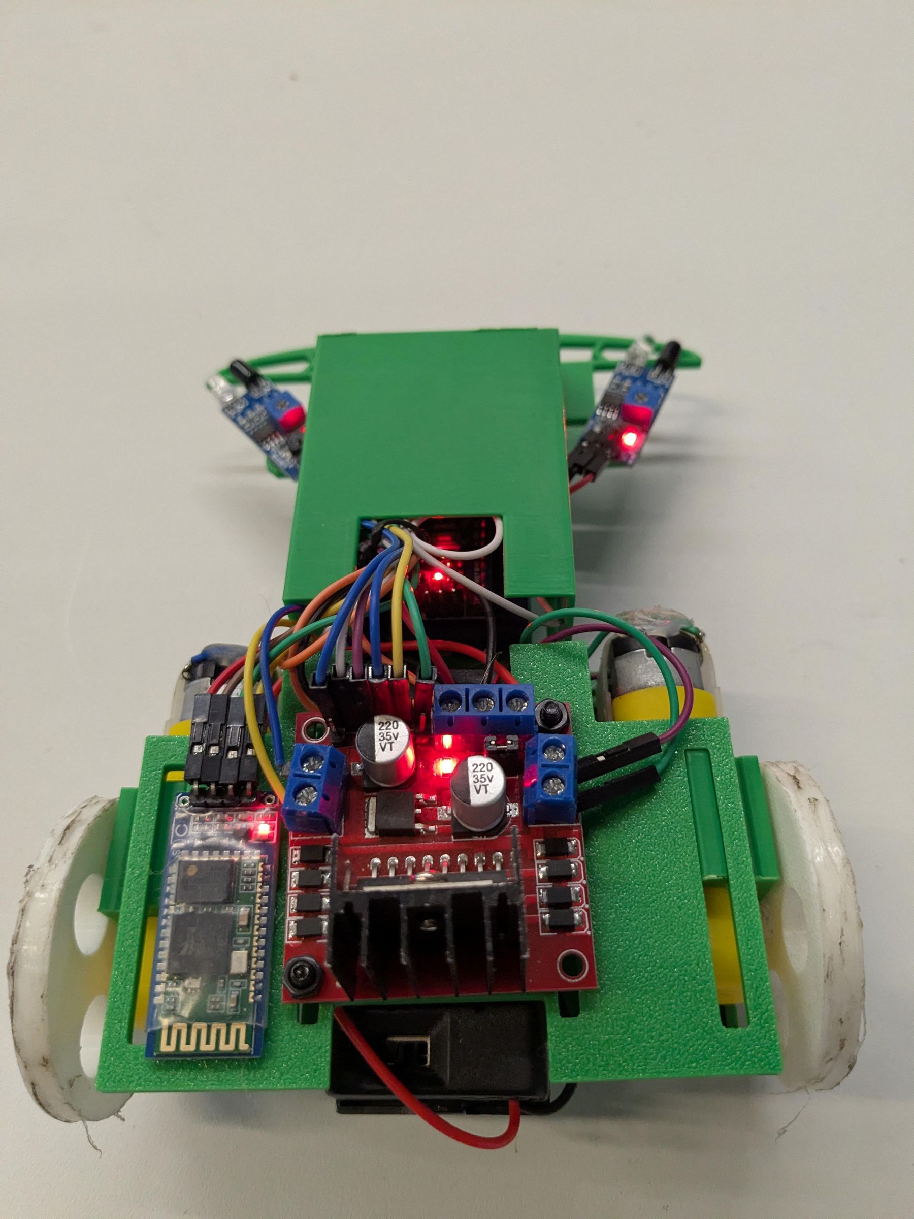
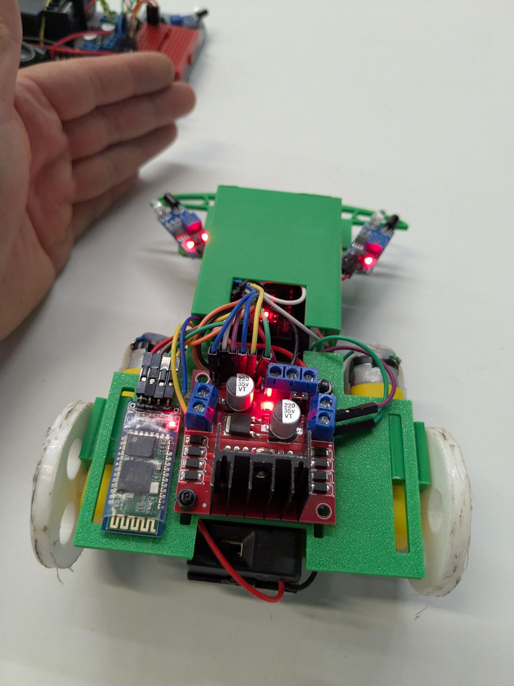
Finally, insert the 9v battery into the battery box and switch the robot on. Make sure a red or green light appears on the L298n, IR sensors, Arduino Nano, and HC-06 (picture 7). If one of these components does not light up make sure the VCC and GND pins didn't get reversed. Once you've confirmed all the lights come on turn off the robot.
Wire the Motor Driver Circuit and Motors
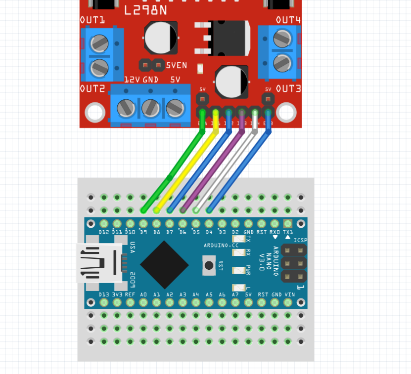
In the following wire diagram I have removed the sensors and Bluetooth module so it's easier to see where the L298n connect to the Arduino. Please do not remove your sensors or Bluetooth module from your robot.
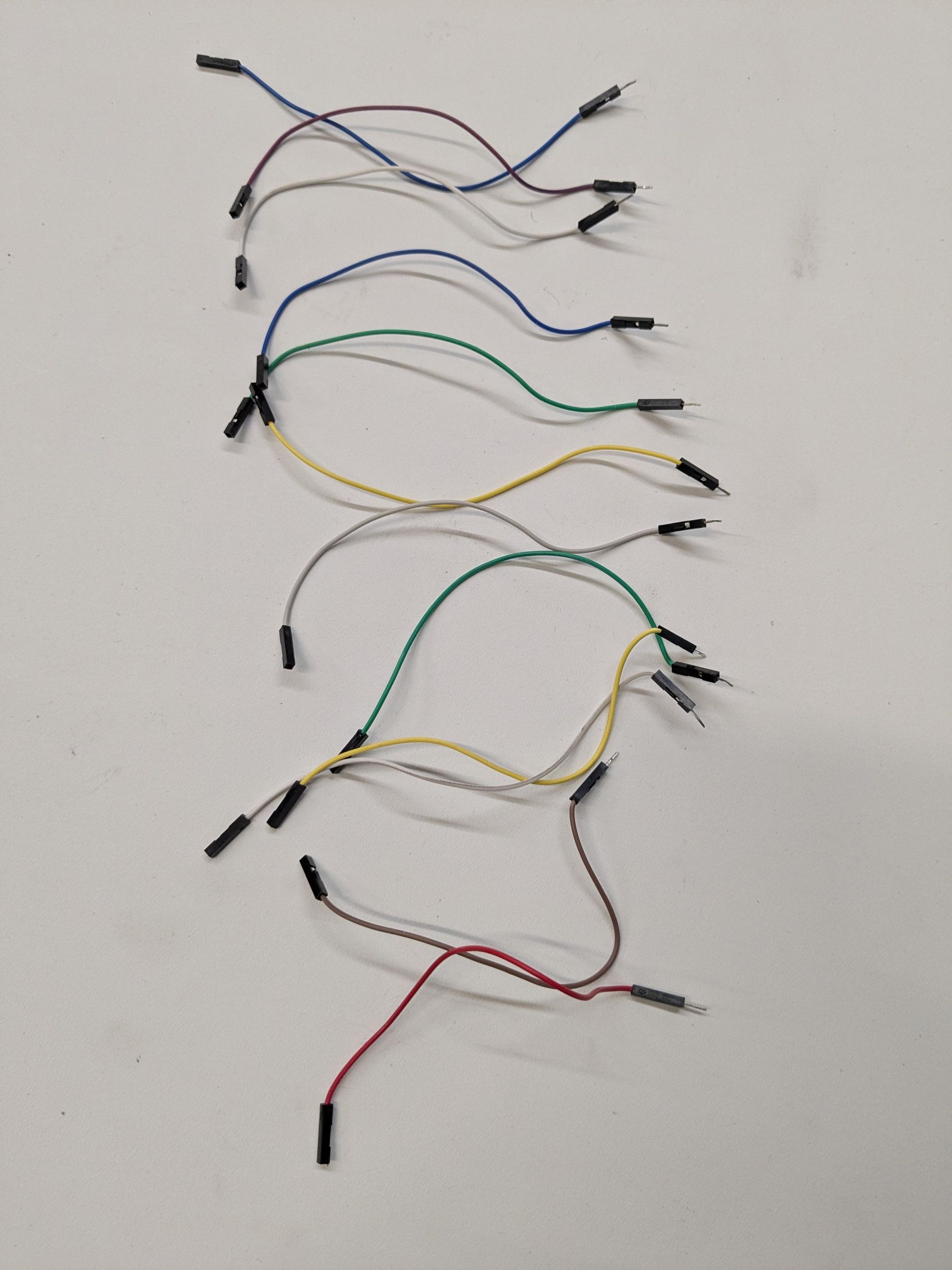
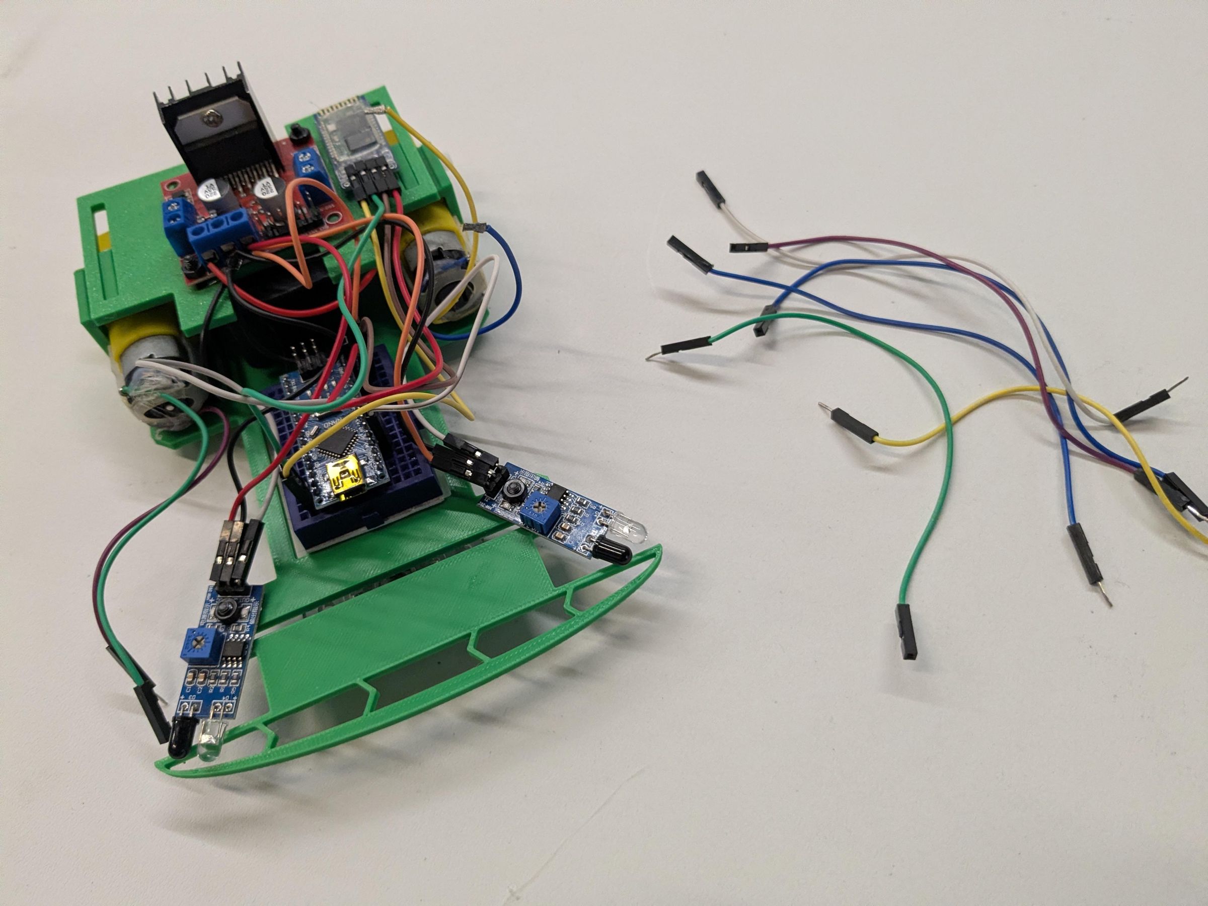
You will need a green, yellow, purple, and white wire along with 2 blue wires (picture 1)
See picture 2 for a guide for the following connections:
- Take the female end of the Green wire and insert it over the ENA pin on the L298n.
- Take the male end of the Green wire coming from the L298 and insert it into the mini breadboard next to the D9 pin on the Arduino Nano.
- Take the female end of the Yellow wire and insert it over the IN1 pin on the L298n.
- Take the male end of the Yellow coming from the L298 and insert it into the mini breadboard next to the D8 pin on the Arduino Nano.
- Take the female end of the Blue wire and insert it over the IN2 pin on the L298n.
- Take the male end of the Blue wire coming from the L298 and insert it into the mini breadboard next to the D7 pin on the Arduino Nano.
- Take the female end of the Purple wire and insert it over the IN3 pin on the L298n.
- Take the male end of the Purple wire coming from the L298 and insert it into the mini breadboard next to the D6 pin on the Arduino Nano.
- Take the female end of the White wire and insert it over the IN4 pin on the L298n.
- Take the male end of the White wire coming from the L298 and insert it into the mini breadboard next to the D5 pin on the Arduino Nano.
- Take the female end of the Blue wire and insert it over the ENB pin on the L298n.
- Take the male end of the Blue wire coming from the L298 and insert it into the mini breadboard next to the D10 pin on the Arduino Nano.
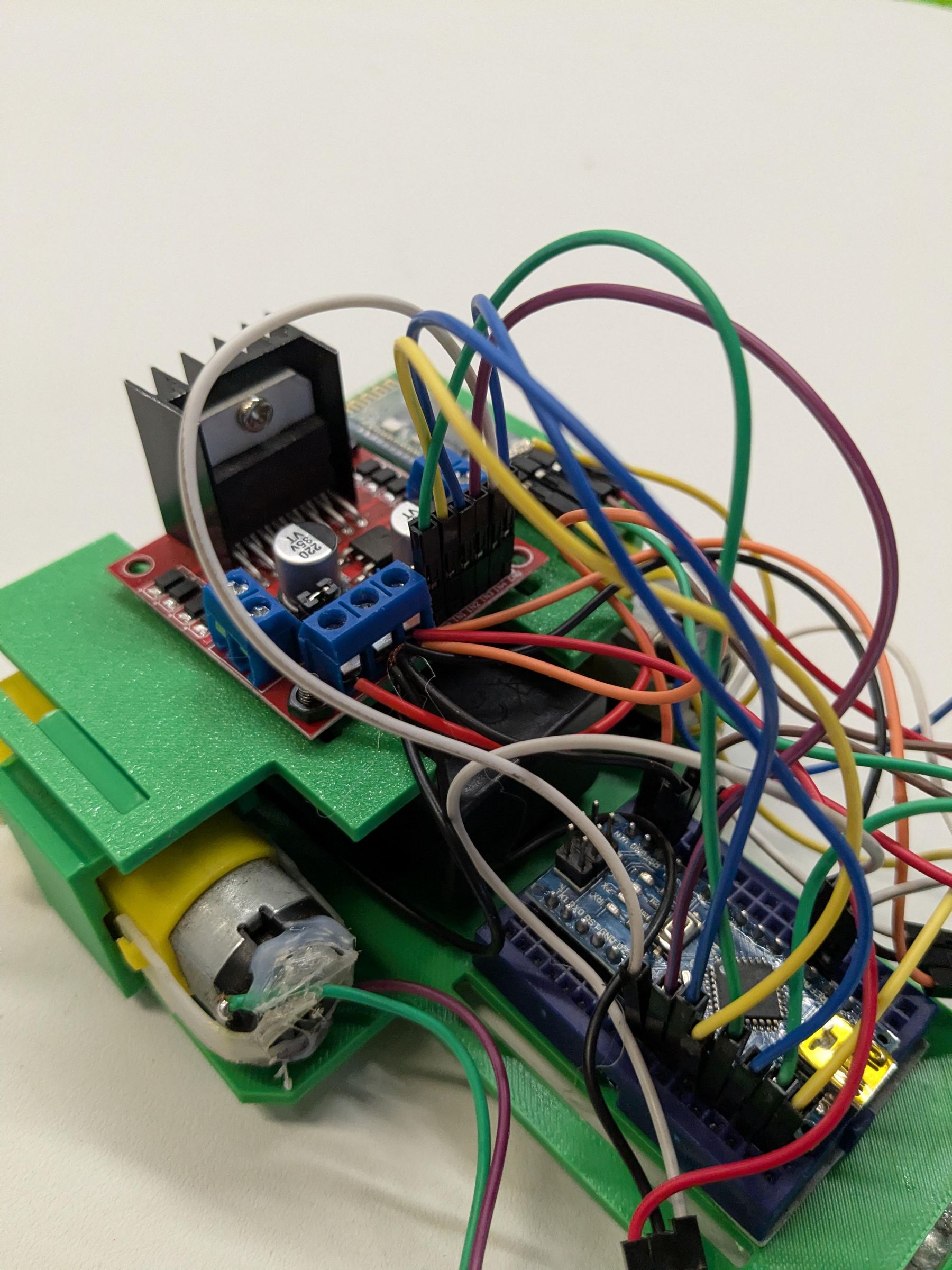
Finally, loosen the motor inputs on the L298n. Insert the left motor wires into the motor inputs on the L298n and tighten down. Don't worry about what motor wire goes where, we'll address that in Step 8. Do the same for the right motor (picture 3).
Wire Management and Cowl
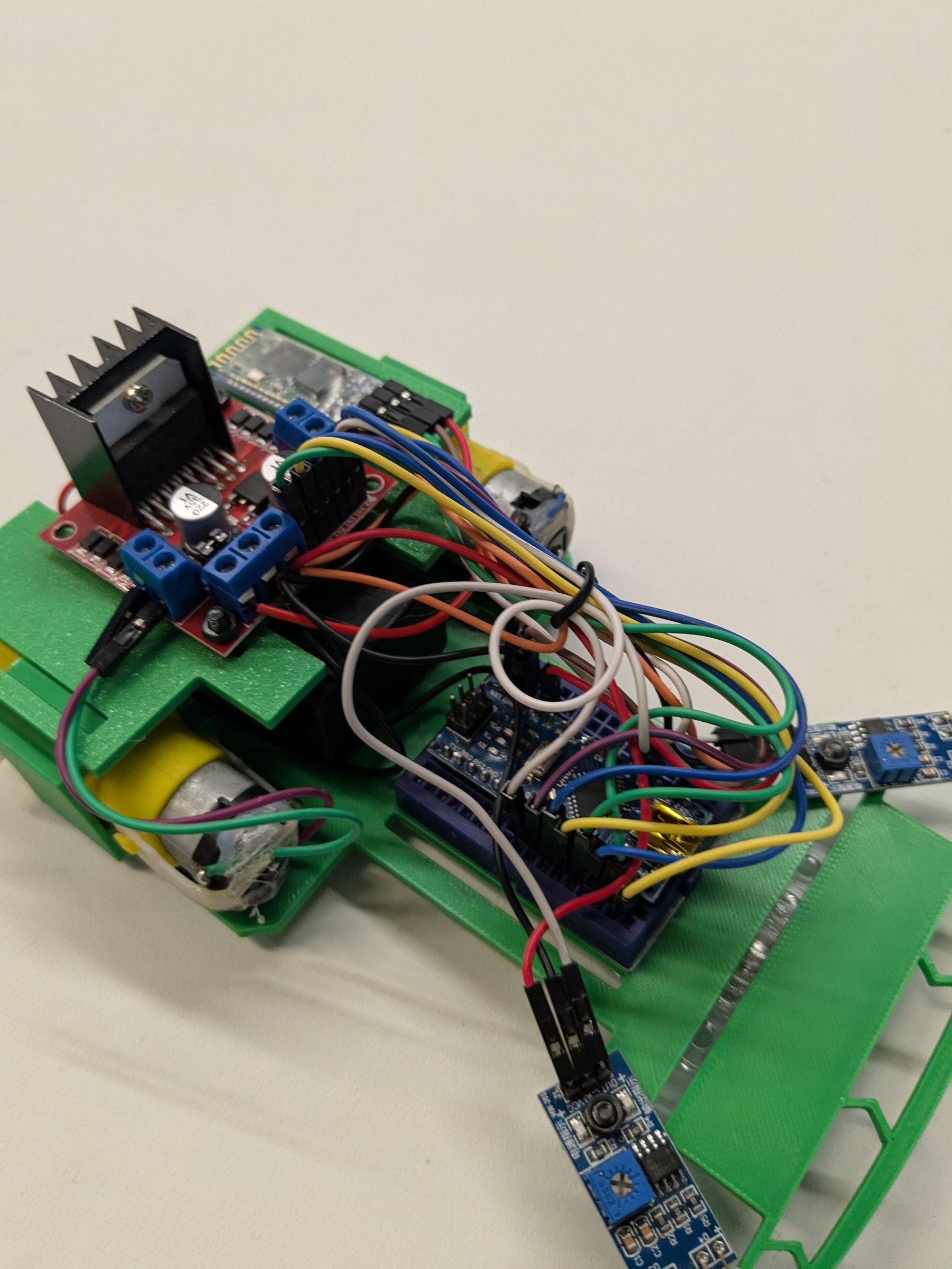
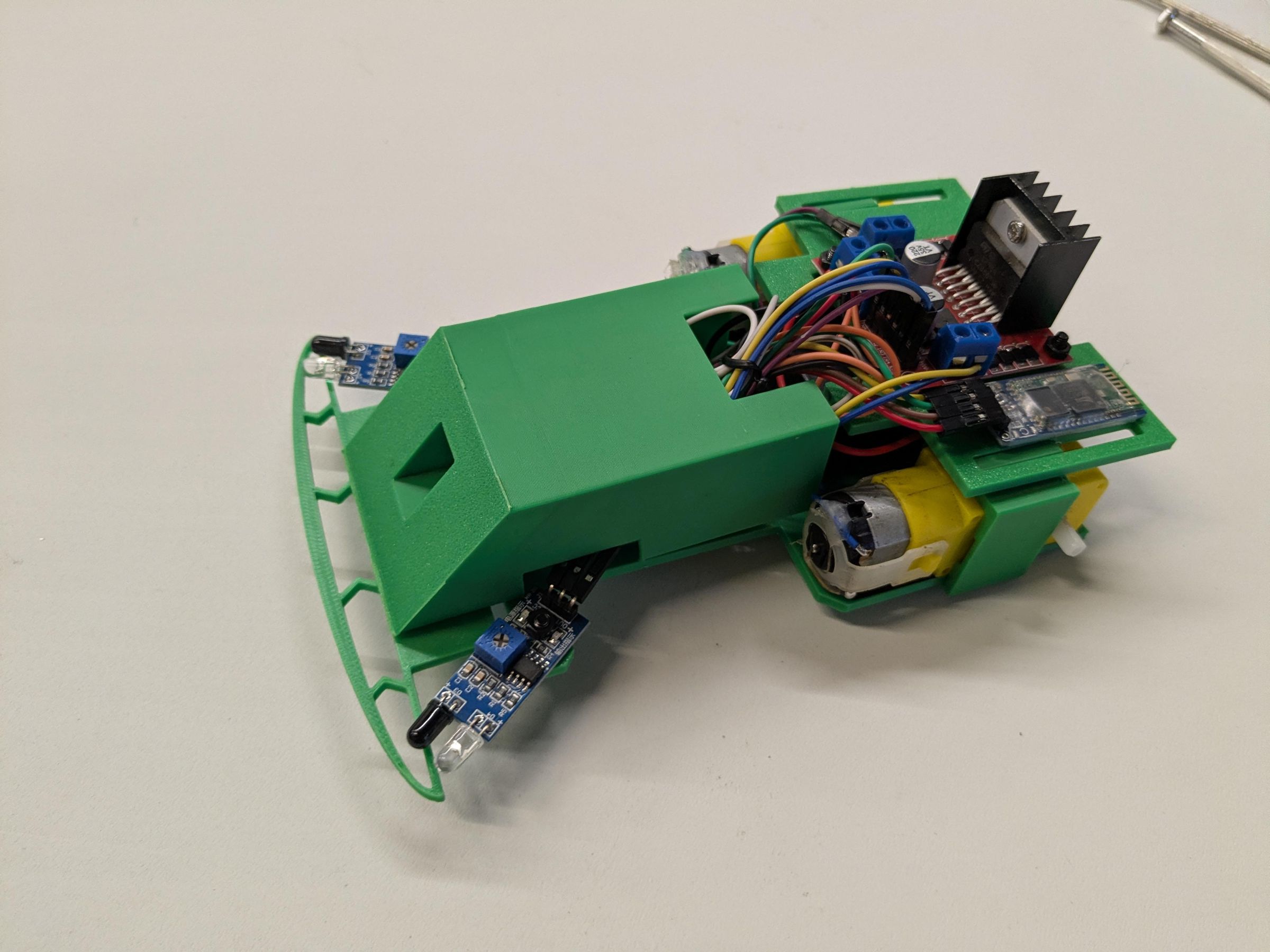
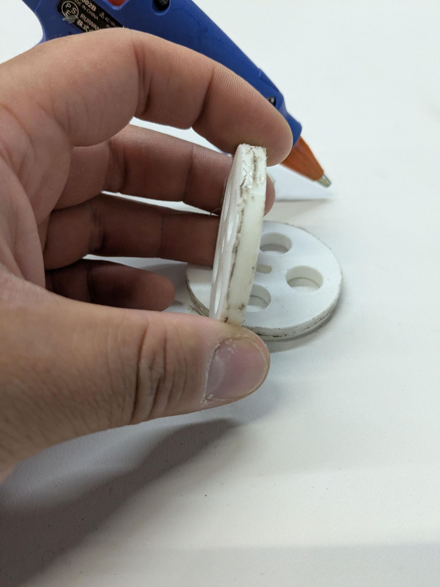
By now you'll probably notice the spaghetti mess of wire sitting on top of the robot. To clean this up I gently gather all the wire into a bundle and use a recycled bread tie to keep them together, you could also use a small zip tie (picture 2). Once the wires are bundled together I make sure I didn't pull any of them out from the breadboard or sensors. Next, I line up the cowl with the front of the robot and press it into place (picture 3). The adhesive from the caster will hold the cowl in place. The hole in the front of the cowl is used to insert the USB cable for programming. Using hot glue coat the outside of the wheels with a thin layer to create a grippy surface (picture 4). Finally, align the center hole of the wheels with each motor shaft and press them in.
Upload Code
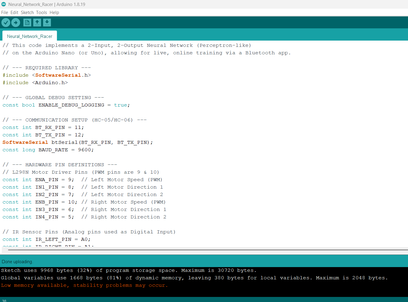
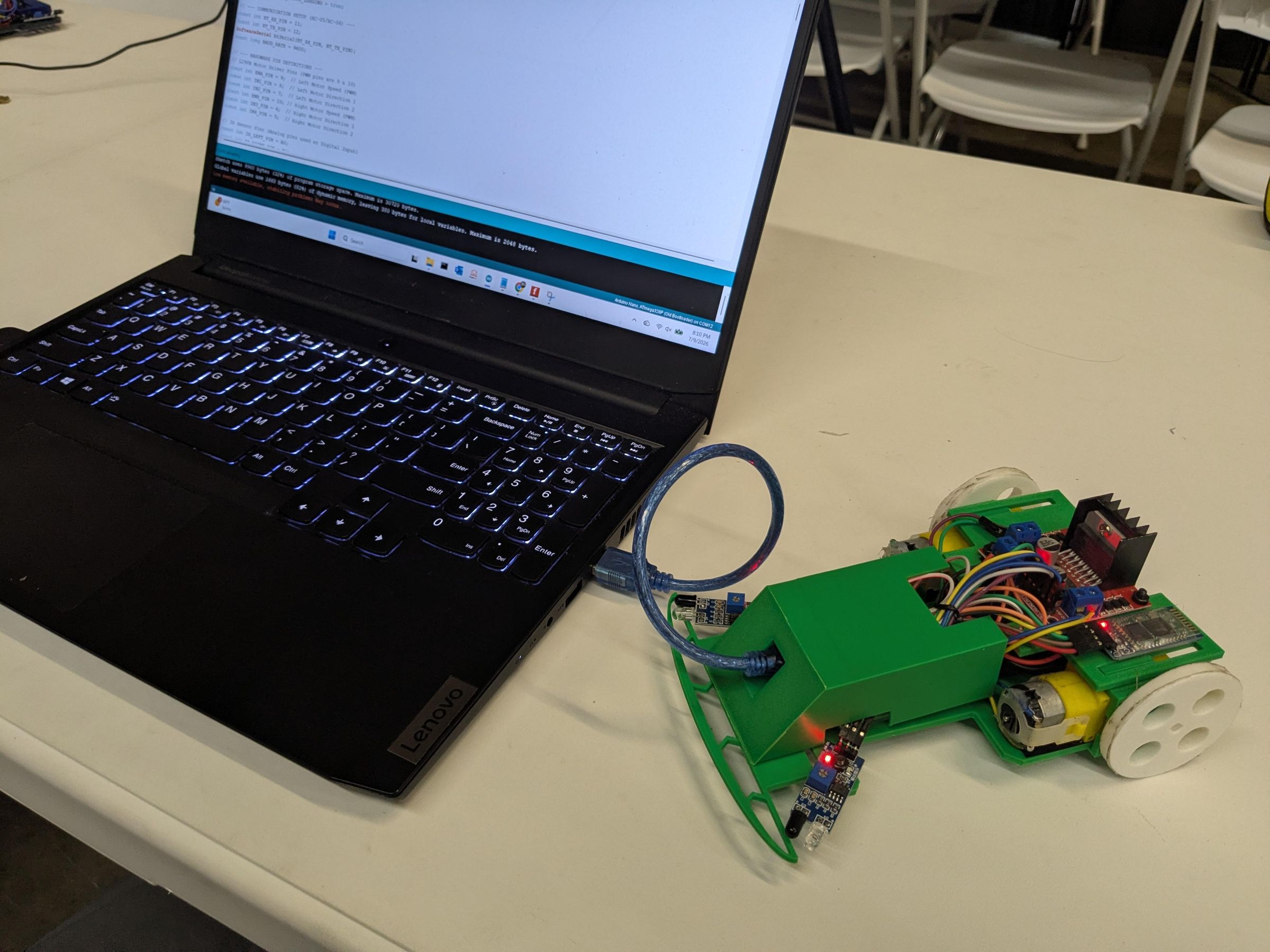
To get the code on the robot you will need to download and install the Arduino IDE for your device's operating system, Windows, Apple, Linux, etc. You can find the IDE here on the official Arduino site: https://www.arduino.cc/en/software
You can find the code for the Arduino Neural Network Racer attached to this step. If you haven't used the Arduino IDE or uploaded coded please use the following tutorials:
Arduino official tutorial: https://support.arduino.cc/hc/en-us/articles/4733418441116-Upload-a-sketch-in-Arduino-IDE
Arduino Clone CH340 upload: https://learn.sparkfun.com/tutorials/how-to-install-ch340-drivers/all
Downloads
Install App and Test Motors
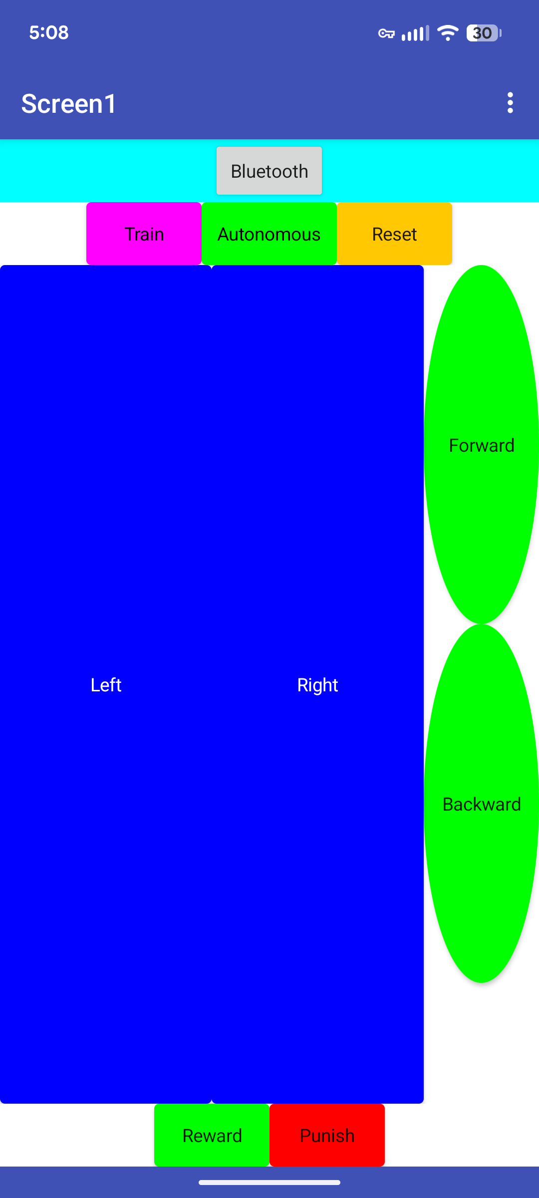
Now that you have the code uploaded to the robot you are ready to install the controller app and get the robot's motors direction sorted.
Download the BLE Controller for Arduino Neural Network Racer from the MIT App builder here: https://gallery.appinventor.mit.edu/?galleryid=c0345513-3b4b-4e4d-bb22-75a7cf1357c9
You can find a tutorial on how to download for Android and IOS at the MIT App Builder website here: https://appinventor.mit.edu/explore/ai2/build
Once the app is installed you will need to pair the robot to your device.
- Turn on the robot.
- Navigate to Bluetooth settings on your device.
- Select pair new device
- Find HC-06 and pair
- Input the default pin 1234 if asked.
- If 1234 doesn't work try 0000
- Open your Bluetooth settings and you should now see HC-06 listed as a paired device.
- If you don't see it reference this tutorial: https://www.martyncurrey.com/the-complete-guide-to-the-hc-06/
Please reference the first picture to see what each button does. You can click each button on the picture to get a short description.
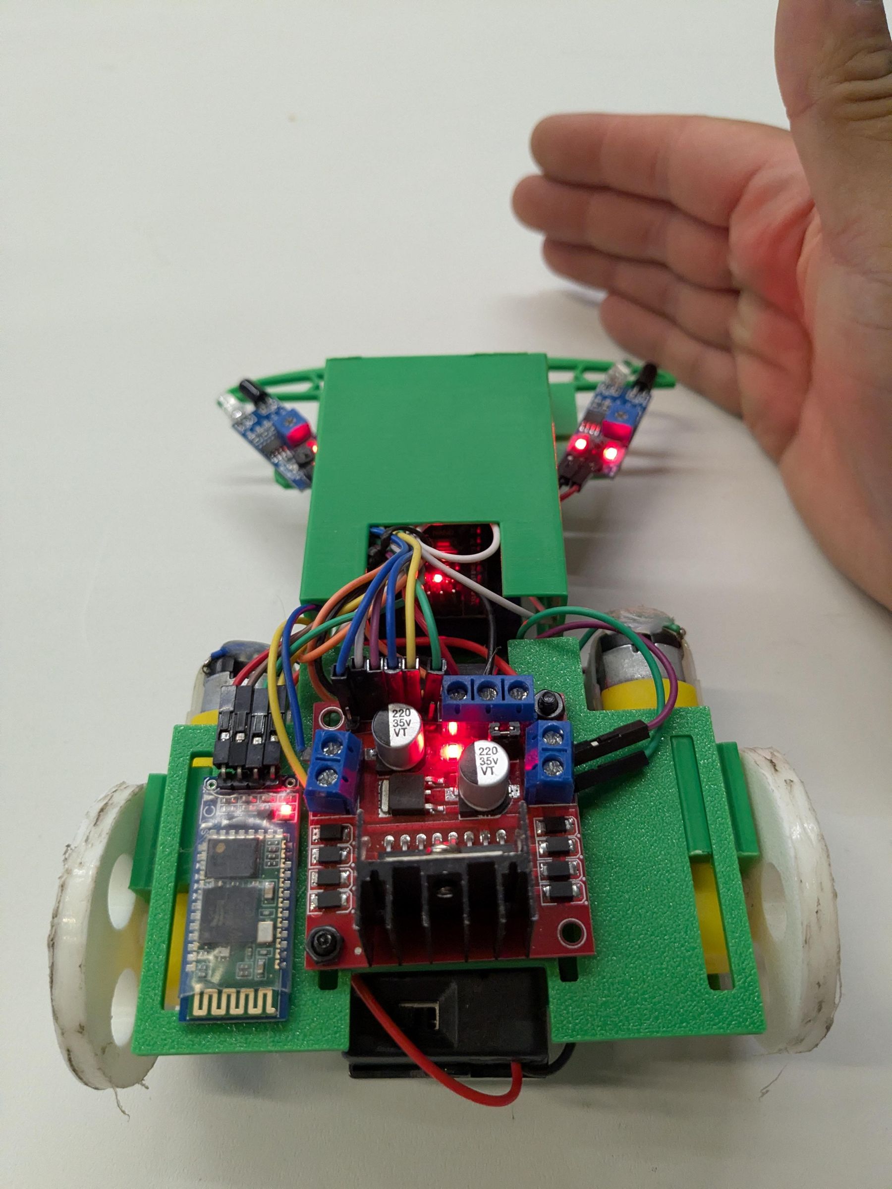
Once you have the robot paired place it on a spare motor clip so it doesn't run away when you test each motors direction (picture 2). Turn on the robot and open the app. Select the Bluetooth button to get a list of paired devices. Find the HC-06 and select it. Now that you are in the main screen tap and hold the forward button. Both wheels should be moving forward. If the wheels are not let go of the forward button and locate the L298n port that is connected to the motor going in the wrong direction. Loosen the ports and swap the wires between them to reverse the motors direction. For example if the red wire is in port 1 and the black one is port two remove both and swap there positions. So Red would go to port 2 and black to port 1. See picture 3 for the orientation of the robot when it's driving. Think of it like a vehicle you would drive in a video game from the rear view.
Training the Robot
If you've reached this step you have a working robot and that's awesome!
Before we start your robot here's a simple description on how it works:
Imagine a robot that starts out completely blank. It has "eyes" (sensors) to see its surroundings and "muscles" (motors) to move its wheels, but its brain is empty. It has no pre-programmed rules telling it how to drive.
Instead of being programmed with a keyboard, it learns by watching you. To teach the robot safely, you place it on a stand so its wheels can spin freely in the air. You then use your hand or an object to trigger its sensors while pressing the steering buttons on your remote control app. During this time, the robot acts like a student copying a teacher. Every time you trick its eyes into seeing an obstacle, it pays close attention to what you tell the wheels to do.
Inside the robot's digital brain, there are invisible "knobs" that connect its eyes to its wheels. Every time you make a driving move, the robot automatically twists these knobs to match your behavior. For example, if you cover the left sensor to simulate a wall, and you press the "turn right" button on your app, the robot turns up the knob that connects "seeing a wall on the left" to "spinning the wheels to the right."
After a minute or two of showing it different combinations of sensor triggers and motor movements, the robot has collected enough examples. You press a button on the app, and the robot locks its knobs in place. Now, you can take it off the stand, put it on the floor, and let it drive on its own! When its eyes actually see a real wall, the signal flows through those knobs you helped adjust, and the robot automatically steers exactly the way you taught it on the stand. In short: You didn't write code to tell the robot how to drive; you taught it by setting a good example!
To train the robot set it on an extra motor clip, power it on, connect it to the control app, and select train. You have 100 examples you can give it before it's memory is full. One example is recorded every time you press forward, left, and right. You can pair these examples with sensor input. For example if you trigger the left sensor with you hand you can press turn right to teach the robot what it's supposed to do when the IR Sensor detects an object on the track. The robot will stop moving and accepting input once its memory is full. Please note the training memory is volatile, which means if you turn off the robot or hit reset it will be gone.
Time to Go Autonomous
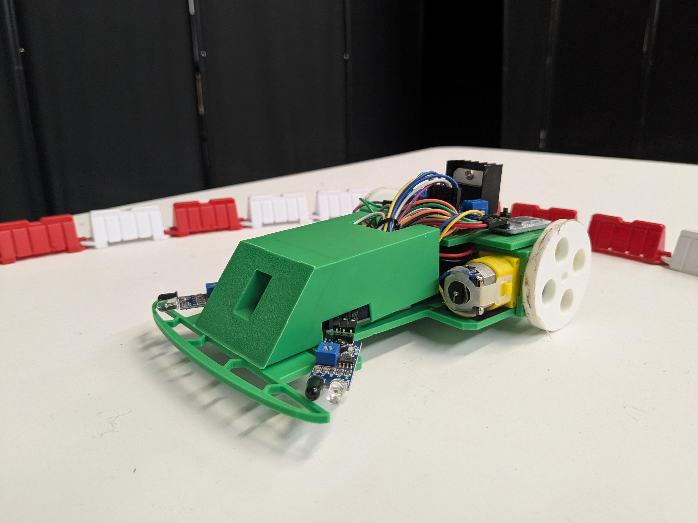
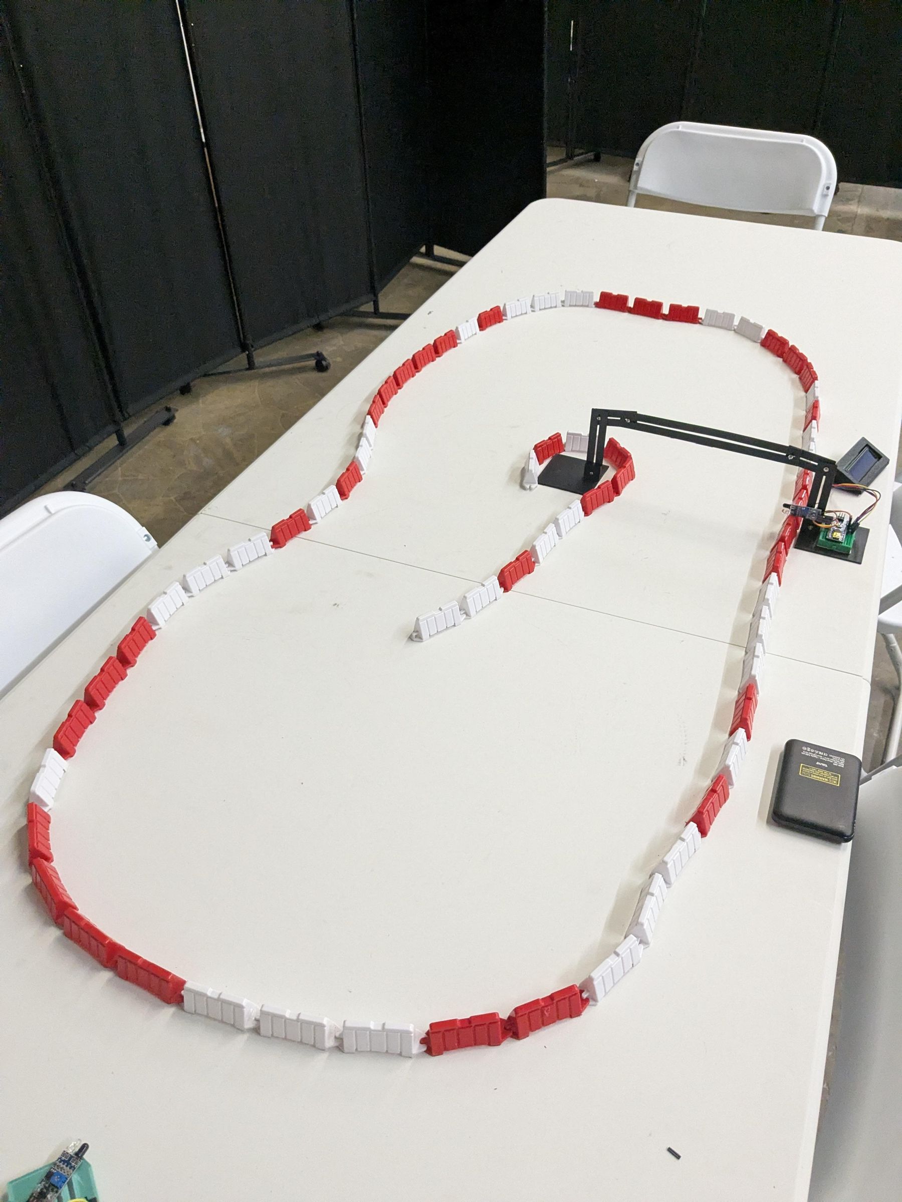
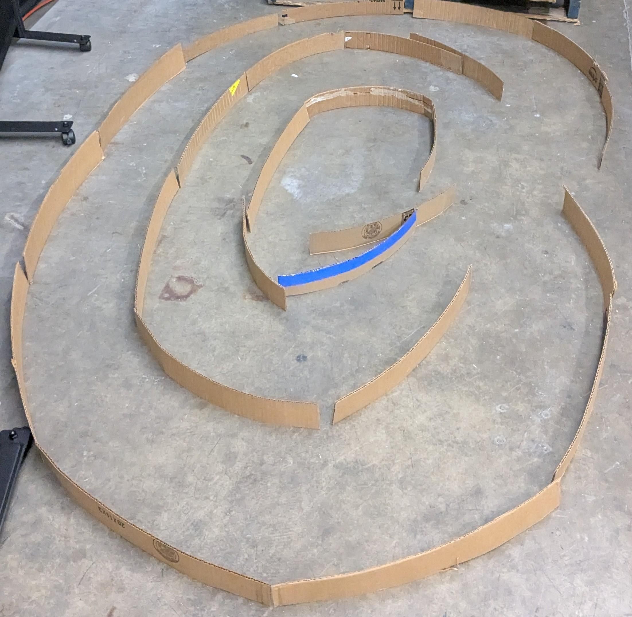
Once your robot is trained it's time to put it on the racetrack and see how well it learned. The robot navigates the track by detecting walls and hopefully steering away from them. I use RC drift barriers from Amazon but you can use pretty much anything as long as it's not matte black. Dark matte colors absorb the IR light which will cause the robot to not be able to see the wall. The IR sensor work by emitting IR light and waiting for it to be reflected back into it's receiver to detect an object. Another great way to make a track is to use strips of cardboard see picture 3. When you're ready put the car on the track and select the Autonomous mode. If you like how the car is driving you can select Reward on the controller to encourage the behavior. When you reward the robot you will see it speed up and/ or make smoother turns. If the robot is not driving well you can select Punish button which will stop the robot and it will reconsider it's training. To start again press Autonomous button again. If you notice the robot is making the right decisions but the motors don't move when you place it on track this points to not giving it enough training to move forward. You can remedy this by rewarding the robot 4 or 5 times. The robot is doing the right motions just is not putting enough power to moving forward. You can encourage it with rewarding it's efforts.
Making It a Race and Event
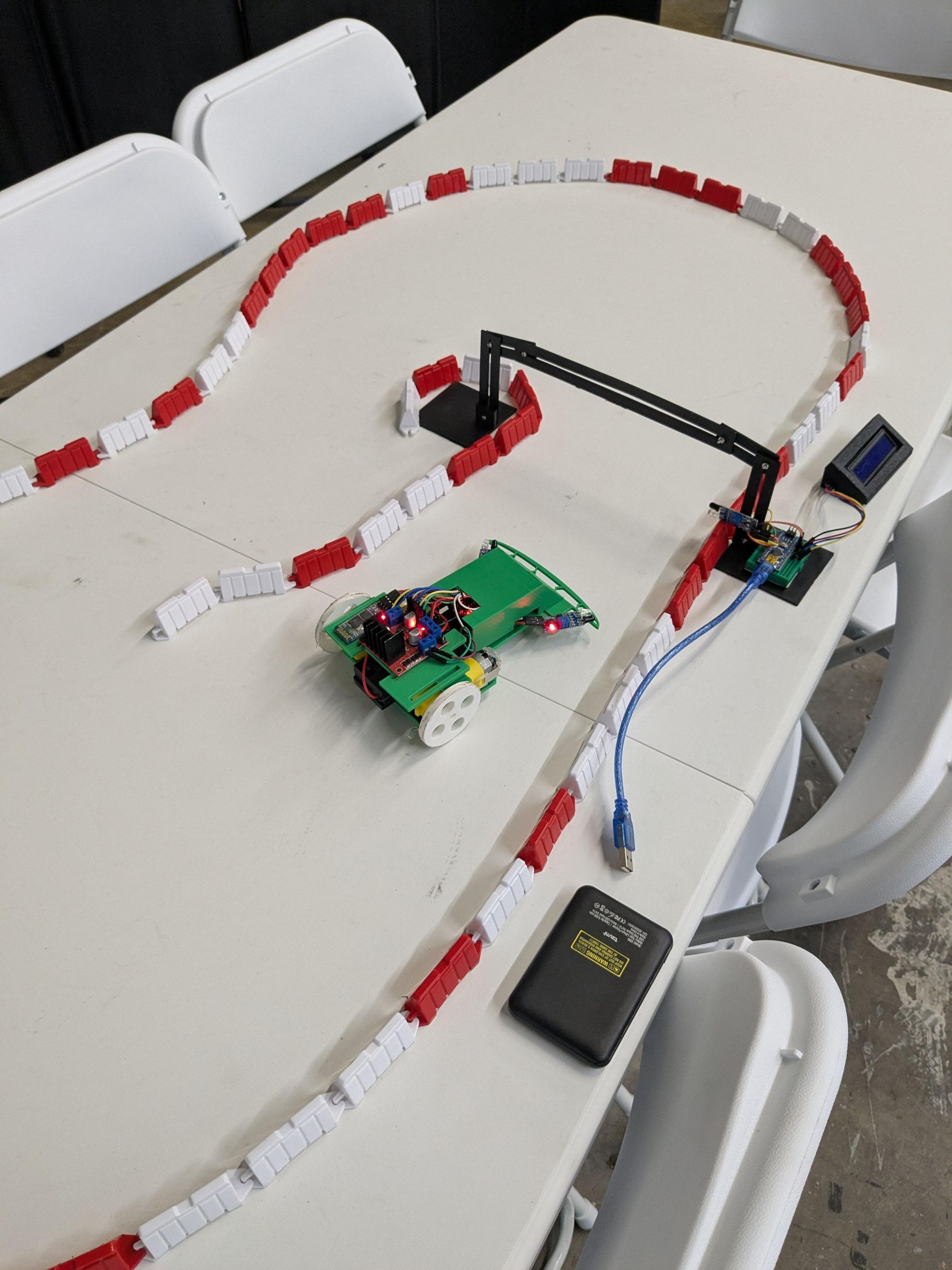
You will notice on my track there is a gate. I made simple track timer using an Arduino to log my robots lap times. This allows me to measure the robots performance over training sessions. I haven't published the Instructable for my timing gate yet but plan to soon. If you would like to time your robot you can mark the start and finish line with blue tape then use a stop watch or your phone to time your robot's laps.
Making it a Race (Event)
At Tech Rockstar Academy we use my Arduino Neural Network Racer to let youth get hands on with learning how AI works. The program last for about two hours where participants make a simple version from this Instructable: https://www.instructables.com/Autonomous-Robot-Racer-Analog-Mode-no-Microcontrol
With the simple robot racer the participants learn how the sensors and motor driver work to make the robot car navigate the track. They also learn how to tune the car mechanically to make it go faster. After the participants are comfortable with handling the robots I bring out the Arduino Neural Network Racer and show them how they can train it to drive around the course. I will usually include a short presentation on autonomous vehicles and EVs as well. The Arduino Neural Network Racer last for about 20 minutes on a single battery so I have extra incase the program goes over time. Once everyone knows how to train the robot we hold a friendly time attack competition. The participant who trained their robot to get the fastest time on the track after 3 tries wins the competition and receives robot wheel as a trophy. If you would like more details on how to run your own robot race please comment below and I will try to assist with your event.
Resources
If you would like to learn more about neural networks or autonomous vehicles please check out this list of links:
Other Autonomous robot racers you can build:
https://www.instructables.com/Autonomous-Robot-Racer-Analog-Mode-no-Microcontrol
https://www.diyrobocars.com/2017/10/01/a-minimum-viable-racer-for-openmv/
Books
Driven: the Race to Create the Autonomous Car
Videos