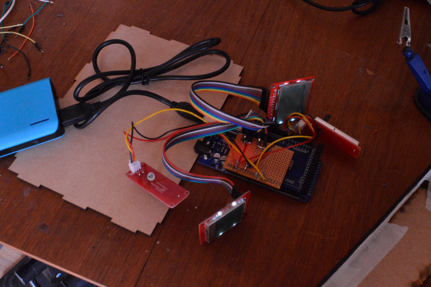
Arduino Pong 3000

This guide will let you make a playable Pong game, based on an Arduino, with sound coming from a Teensy.
For this, you will need the following components:
Arduino:
- 2x Nokia 5110 lcd;
- Arduino Mega 2560
- 2x Crowtail Linear Potentiometer (10k Ohm)
- Protoboard (Optional)
- Male-Female Jumperwires
Teensy:
- Teensy 3.6 (or older with the Audio Shield;
- Jumperwires (8x, 4 white, 2 black, 1 red, and 1 yellow);
- 2x Audio amplifier LM386;
- 2x Speaker (more than 2 watt, atleast);
- Teensy header;
- Protoboard;
- (optionally) soldering cables (colored);
Case:
- 300x500x3mm MDF Board
Arduino Construction + Code: the Game


1
The first step is to plug in and test the displays. You can do this with the M - F cables. The first one plugs in like this:
CLK= 13 DIN= 11 CE= 10 DC= 9 RST= 8 VCC and BL= 3.3V & GND= ground.
I used a soldering plate for VCC, BL, and GND. You can solder those wires together some other way if you prefer. The second LCD uses the same plugs for VCC BL and GND but the other connections go to different digital pins:
CLK= 7 DIN= 6 CE= 5 DC= 4 RST= 3
If you have all of this soldered together you can upload this code to your arduino mega: https://drive.google.com/file/d/1RvEnwrdS72luBqTW...
If you did everything right it should start playing pong on its own already!
How to Make It Playable


So far, Pong is able to play itself. I take it you want to be able to have human interaction with your box. For this, we connect the 2 linear potentiometers, to do this i cut of the end of the included connector leaving 3 exposed wires. The red one is connected to 3.3V. And the black one to ground. Do this for both. Now connect the yellow wire for one of the sliders to analog pin 1 and the other to analog pin 3.
If you test it out now you should be able to control the paddles. You can take over anytime during the game and if you stop moving the controls the ai will take over again.
Teensy Construction: the Sound


Because the Arduino doesn’t have enough memory on it’s own, you need a seperate device that can output audio. The teensy 3.6 has stereo 12-bit audio, so we’ll use that. The speakers probably will need an amplifier to work, due to the low voltage it would otherwise receive. The LM386 has a VCC in, which works well enough with the 3.3V the Teensy provides, although it recommends 5V to 12V. We also need 4 cables that give the teensy data from the arduino, on which sound should be playing. 4 digital signals means 24 = 16 different sounds.
Solder a header for the teensy to sit in, and solder Ground, 3.3V, analog pins 21 & 22, and digital pins 0,1,2 & 3 to connectors. Solder the Ground to both GND connectors and 3.3V to VCC on the amplifiers Solder A21 (DAC0) to the left speaker, and A22 (DAC1) to the right speaker.
There we go! All you need now is to solder wires to your speaker, and screw them into the LM386 boards. The LM386 board are backwards, because they come standard with their connections on the wrong side. If your sound is too soft/too distorted, turn the potentiometer til the audio is just right on both speakers.
Teensy Code

After you've made all connections properly (and hopefully tested it with a multimeter...), It's time to get the code on your software.
If you've never worked with a Teensy before, you need a program called TeensyDuino, which lets you program Arduino code in the Arduino IDE for the Teensy.
After you've installed this, make a folder with whatever name you desire, and put all the files from the following folder in it:
https://drive.google.com/file/d/1zhLX8cYaasuOh0IfK...
Compile and upload the code to your Teensy. Boom! You should now hear a startup sound for your Pong game! if not, check for errors in earlier steps, or move the potmeter on your LM386 amplifiers a bit.
To get the data from the Arduino, connect the digitalpins 0,1,2,3 to the Arduino pinouts 30,32,34,36, in that order.
The Case


1 First you cut out all the pieces of wood on a laser cutter, here's the file: https://drive.google.com/file/d/1PcmuXojzBNR72NN0YEknIH1bSqgI-jTt/view?usp=sharing
2 Now its time to slot all the pieces in the case hotglue them in, and close up the case, just be sure you leave the back piece open so you can easily power the thing by throwing in a powerbank.
Profit!

And there you go! Have a friend over, and enjoy the first computer game ever made, right on your DIY console!